1
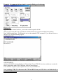
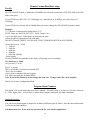
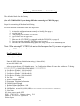
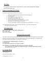
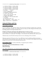
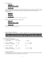
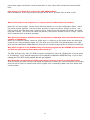
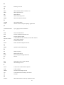
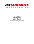
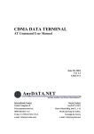
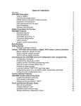
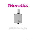
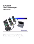
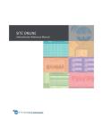
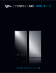
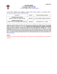
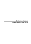
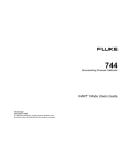
Draft
DATEREMOTE, INC
CDS-9020 MANUAL
ARC Electronics
800-926-0226
1
Table of Contents
Overview ………………………………………………………………. 3
Description ………………………………………………………………………… 3
Standard Feature …………………………………………………………………………
Optional Features ………………………………………………………………………..
CDS-9020 Layout ………………………………………………………………………..
LED Descriptions ………………………………………………………………………….
Specifications ………………………………………………………………………….…
4
4
5
5
5
Getting Started ……..………………………………………………………………… 6
Standard package contents …………………………………………………………………
Connecting to the CDS-9020 ………………………………………………………….….
Dialing into the CDS-9020 Programming Menu …………………………………………
Example of Communication setup for remote dialing or local setup ……………… ……
Exiting from the Configuration Menu …………………………………………………….
7
7
7
8
9
Setting up Telephone Service ……………………………………………………… 9
Things you need to ask the Cellular provider before getting started …………….. 10
Things to tell the Cellular Carrier ………………………………………………... 10
Programming phone number …………………………………………………..... 10-11
Displaying Signal Strength ……………………………………………………………... 11
Remote Com Baud Rate setup …………………………….……………………………. 12
Program Alarm Number ………………………………….…………………………….. 12
Optional Features …………………………………………………………….……
12
Setting up CDS-9020 Modem Init string ………………………………………….……. 13
AT-Commands, if your having difficulties connecting to CDS-9020 ……………….…. 13
Site Name ……………………………………………………………………………….. 14
Steps for customizing the Site Name ………………………………………………….. 14
Why set-up the Windows? ……………………………………………………………… 14
Programming Clock ……………………………………………………………………. 15-16
Setting up the Start and Stop Windows ………………………………………………... 16-17
Programming Cellular Phone Number Remotely …………………………………….. 17-18
RS-232 Setup …………………………………………………………………………… 19
3 Wire RS-232 Connections ………………………………………………………….…. 20
CDS-9020 Programming Cable wiring Diagram …………………………………….… 21
CDS-9020 DB-9 Male to a DB-25 Female Diagram …………………………………… 22
CDS-9020 Terminal Block to a DB-25 Female ………………………………………… 22
Setting up Host PC Modem …….……………………………………………………….. 23
Generic AT String ………………………………………………………………………. 23-24
Commands Reference …………………………………………………………….……. 24
CDS-9020 Cellular and PCS CDMA AT-Commands ………………………….……… 24
QUALCOMM Proprietary Commands Table…………………………………………... 25
Basic AT Parameters …………………………………………………………………… 25-26
S-Registers ……………………………………………………………………….……. 26-27
Cellular CDMA Commands ……………………………………………………….….. 28-29
Basic Action Commands ……………………………………………………………… 27-29
What is CDMA? ………………………………………………………………………. 30
How the technology Works? ………………………………………………………….. 30-31
RS-232 Characteristics ………………………………………………………………... 32-35
Trouble shooting problems …………………………………………………………… 35-36
Glossary Of Wireless Terms ……………………………………………………..
2
37-39
Overview
This documentation describes all the features, functions and interfacing to the CDS-9020 products to other DTE
(Data Terminal Equipment). This manual was written for people who have a basic understanding of DCE (Data
Communications Equipment) products.
DESCRIPTION
A self contained cellular/PCS system that is cost effective for remote telemetry/meter reading, data
application and AVL applications. The CDS-9020 establishes a new industrial benchmark for accurate and
efficient data communications at an affordable price.
The CDS-9020 is a complete 19,200bps digital cellular or PCS modem standalone modem. It works at
800MHz or 1.9MHz. DCE (Data Communication Equipment) is setup to communicate from 1200bps to a
maximum throughput of 19,200bps. It does not support auto baud rate detection.
It works like a standard landline modem and is compatible with 95% of host modems. Since the CDS-9020
uses IS-95A and IS707 CDMA-one standard. You will see a much more reliable connection then when using
standard analog cellular modem for your remote data retrieval.
CDS-9020 is much more then just a standalone modem. It has menu features to configure the unit locally or
remotely. It has four programmable windows so you can turn the unit on and off to conserve power at certain
times of the day or night. Programming the phone/NAM is a snap, you don't have to go to the local cellular
provider, with the programming menu we embedded in the firmware. It just walks you throw step by step.
CDS-9020 can be upgraded to a CDS-9021/A. CDS-9021 is the same PCB board as the CDS-9020 we
manufactured the board to add extra features. Such as a wireless\cellular analog modem module and a GPS
module for tracking (AVL applications).
You can order these extra modules at the same time of purchase or, place the orders as you go. If the
CDMA-one coverage footprint does not cover the area that you are planning to use your CDS-9020. You would
order part# CDS-9021/A (the A stands for the analog modem module). With this add on feature it gives the
CDS-9020 the ability to operate in analog or digital mode. In addition, you still get the same low rates of a
digital phone line .
If you order the unit without the analog modem module, and the site you plan on using the CDS-9020 does not
have CDMA coverage you can order an analog module after you installed the unit, Part Number CDS-9022
Module.
For the GPS-AVL user who needs coverage nationwide, the CDS-9020/AG is the unit you would want to order.
This unit comes with a CDMA modem, GPS module, and 1 Meg of memory for downloading archiving data
and an analog modem module so you can track your vehicles anywhere and anytime, with most tracking
software.
Safety precautions for the user
The following notes refer to OEM module for the CDS-9020/CDS-9021 Series Modem Cellular Engine and to applications based on
CDS-9020/CDS-9021 Modem. The end user of an application based on the CDS-9020/CDS-9021 Modem Series must incorporate
these safety precautions into his/her instruction manual.
2.1 Electrical safety
3
The lowest input voltage that can be applied to the CDS-9020 is 10.5VDC; the highest voltage that can be used is 24VDC
2.2 Aircraft safety
Cellular engines can interfere with an aircraft’s navigation system and its cellular network. The use of CDS-9020/CDS-9021 Modem
on board aircraft is forbidden by federal law
2.3 Safety on the road
a) It is not permitted to signal incoming calls by sounding the vehicle’s horn or flashing the lights.
b) In case of emergency. Use the hands-free option to speak only if it does not divert your attention from the traffic.
2.4 Electronics in medical equipment
Radio transmitters, including cellular engines, can interfere with the operation of inadequately protected medical devices. Please
address all questions to a doctor or the manufacturer of the medical device.
2.5 Precautions in the event of loss/theft of the CDS-9020
If your CDS-9020/CDS-9021 Modem is missing, notify your cellular network operator immediately in order to avoid misuse.
STANDARD FEATURES
Ø
Ø
Ø
Ø
Ø
Ø
Ø
Ø
Ø
Ø
Ø
Ø
Ø
Ø
1 standard DB-9 female, RS-232C interface (DCE)
1 RS-232 modem block DCE connector
Auto answer \ auto dial
Real time clock (supports polling)
User-programmable on site
Site Name \ ID Number
Call progress monitor for trouble free cellular calls
Cellular\PCS network monitoring
Polling windows reduces power consumption
Remote DCE com settings (baud rate)
Antenna Connector: TNC style 50 Ohm female
Hayes AT-Commands
Reboots itself if it detects a problem
Remotely programmable (windows, alarm number, AT-String, NAM /phone#, baud rate,
time and site ID
Ø Low voltage shut off (shuts down if voltage drops to 9.3VDC, will turn back on when voltage
reaches 11.2VDC (Note: this is used for solar/battery applications and telemetry
applications so the battery does not fully discharge).
Optional Features
Ø
Ø
Ø
Ø
Ø
Ø
Ø
Analog modem
GPS module
1 meg of memory
Antenna’s
Solar panel system
Nema 4x enclosure (all weather enclosures)
12VDC power supply
Ø Host modem, cellular ready
4
CDS-9020 LAYOUT
Figure 1 CDS-9020 layout
P1 - RS-232 female DB-9 standard
DCE port, any modem cable will
work.
P2 : RS-232 terminal block (Note:
you can not use P1 & P2 at the
same time) .
P3 : Input power connector
10.5VDC to 24VDC (2 pos
terminal block).
P4 : Analog Modem option
header. (option)
P5 : GPS Module or memory
module header. (option)
P6 : Input from radio module.
P7 : 6 I/O’s digital or analog,
inputs or output.
LED DESCRIPTIONS
D5 = PWR/STATUS: This tells you if you are in a digital mode or analog mode. 1 blink every second =
CDMA mode with CDMA data available, 2 blinks in one second = only CDMA voice mode no CDMA data
available and 3 blinks = Analog mode only.
D4 = Receive Data (RXD)
D3 = Transmit Data (TXD)
D2 = Carrier Detect (CD)
D1 = Data Terminal Ready (DTR)
5
SPECIFICATIONS (physical):
CDS-9020: 3.2"W x 2.75"H x 6"L
CDS-9020 Complete unit mounted in a Nema 4x Enclosure 6"W x 8"H x 4.5"D
SPECIFICATIONS (cellular transceiver 800MHz):
Transmit frequency
Receives frequency
RF Digital output power
RF analog output power
Vocoder
Modulation/demodulation
Antenna impedance
Antenna connector
824 - 848.970 MHz
869 - 893.970 MHz
CDMA 200mW to 600mW
AMPS 600mW
8-16 kbps and EVRC
voice: PM with COPANDER
data: FM
50 OHM
External Mini TNC
SPECIFICATIONS (CDMA 800 & 1.9 MHz/Analog Modem)
error correction/compression
cellular throughput
serial interface
flow control
modulation techniques
MNP 10EC, TX-CELL and V.42/V.42bis
up to 16,000 bps
buffered EIA RS-232C (DB-9 or terminal block)
XON/XOFF, RTS/CTS, or HP ENQ/ACK
CCITT V.32bis (14.400 bps)
CCITT V.32 (9600 bps)
CCITT V.22 bis (2400 bps)
CCITT V.22 (1200 bps)
CCITT V.21 (300bps)
BELL 212A (1200 bps)
SPECIFICATIONS (CDMA PCS 1.9MHz)
Current: 680 mA max.
Transmitter Power: 200 mW
Transmit: 1850 to 1910 MHz
Receive: 1930 to 1990 MHz
Channel Spacing: 50 kHz
Freq. Stability: ±1.0 ppm
POWER CONSUMPTION (COMPLETE UNIT):
Standby current, Window on = 25ma
Quiescent Standby, Window off = 3.2ma
Online Transmit Current (transmitting data) = 210ma to 680ma (greater the signal level less current,
lower signal level the more it draws current)
TEMPERATURE:
Operational Range-30C to 60C (-22F to +140F)
6
Humidity: 95%, non-condensing
GETTING STARTED
Be sure product was shipped complete. If you find anything missing please contact your supplier.
STANDARD PACKAGE CONTENTS
1) CDS-9020 CDMA Modem (mounted in a powder coated box with mount ing holes)
2) TNC Rubber Ducky Type antenna
3) Flat ribbon cable RS-232 modem and programming cable
4) Modem software used for setting up The Configuration Menu
5) User Manual
6) 2 terminal blocks (2 pos for PW, 8 pos for RS-232)
Connecting to the CDS-9020
1. Plug power in, 12VDC into P3 (see figure #1)
2. On initial power up, you should see the CDS-9020 LED lights blinking on and off
3. After the light stops blinking and only the DTR LED and the PWR/Status LED are on,
the CDS-9020 is finished booting up, it takes around 20 seconds
4. Turn on computer / laptop
5. Plug in DB-9 RS-232 Cable to computer (laptop)
6. Start a terminal program (Terminal for windows 3.1, HyperTerminal, PCLUS, etc).
7. Select the correct COM Port in software usually COM 1 in most laptops. (settings)
8. Set baud rate to 19.200bps (Default for CDS9020/9021 Series) Note: if you have changed this setting,
you need to set the DTE to the same baud rate speed you set it to last time you configure the CDS-9020.
If you don’t know what the DTE speed is set to, see page 45, Trouble shooting.
9. Press CTRL-W three times quickly (you need to hold down Ctrl key and press W three times in 1
second)
10. The Configuration Menu will display
(If the Configuration Menu does not display, see page 45 Trouble shooting)
Now you are ready to start programming locally
Dialing into the CDS-9020 Programming Menu:
Note: This can only be done after you have programmed a phone number and system I.D. number into the unit.
Dialing from the host computer with a Hayes compatib le modem.
Execute a terminal software.
Setup your software to dial the site, baud rate (19,2bps default), Com Port. Parity and Flow Control.
7
Example, of communication setup for remote dialing or local setup
Dialing site:
Type AT in your terminal software, your modem should respond with OK.
After you received an OK, It is a good idea to clear the buffer out of your host modem before dialing.
Type, AT&F then hit Enter. To dial into the site use the standard ATDT command. If you did not receive an
OK please see Trouble Shooting Page 46.
See Example below.
ATDTXXXXXXX
After the CONNECT message displays or CD goes high. Press CTRL-W three times within one second, the
Main Configuration Menu will be displayed, after the menu displays.
You can choose an option or press option F to access to your DTE device.
Note: by hitting CTRL-W it disconnects the TXD and RXD from your DTE device and talks directly to
the CDS-9020 controller.
8
See Examples below
************** CONFIGURATION MENU **************
A. Set Receive Window 1 00:00 to 00:00
B. Set Receive Window 2 00:00 to 00:00
C. Set Receive Window 3 00:00 to 00:00
D. Set Receive Window 4 00:00 to 00:00
E. Set Time:
18:12:51
F. Exit to Modem Mode
G. Reprogram Telephone Information
H. Display Signal Strength
I. Remote Comms Baud Rate: 19200
J. Program Alarm Number:
K. Modem Init:
L. Site Name:
M. Auto Answer mode: OFF
ESN: 17900241336
Battery voltage: 11.3
Phone #: 8053399739 System ID: 2
Exiting From the Configuration Menu
Press option F and wait for the screen to go blank
Then Hang-up Telco Line (+++ATH)
Note: If you are in the Configuration Menu for 5 minutes with no activity the CDS-9020 will hang-up
automatically.
SETTING UP TELEPHONE \ DATA SERVICE
Activating DIGITAL \ PCS Phones
Things you need to know before calling the Cellular provider.
1)You need to find out your CDMA carrier in the area you will be using your modem. Two biggest
CDMA carriers are Sprint PCS and Verizon Wireless, both of these carriers have CDMA and analog on
their systems and both of them have coverage in 97 % of the United States. Then you need to
know what the frequency is.
2) The ESN (Electronic Serial Number) of CDS unit. Can be found on back of unit or on your packing slip.
Each manufacture of Cellular \ PCS have their own unique ESN CDS-9020 use a Qualcomm radio module.
So the 179 prefix belongs to Qualcomm, so when the customer service ask what type of phone you have say
Qualcomm.
3) Advised the carrier the area code you will require.
4) You will want your local prefix to make sure you are not dialing long distance even if the phone is in a
different county or state.
9
Things you need to ask the Cellular provider before getting started
1)What is your SID# ? (System ID) example = 00027.
2) Are you a wireline system = B? or a non-wireline system = A?
*THINGS TO TELL THE CELLULAR CARRIER*
1. No voice mail
2. No caller ID
3. No 3 way calling
Note: After all these questions are answered you can figure out all other parameters.
For A/B select, if the cellular provider is a wireline company enter B ONLY or NO ROAMING
If the cellular provider is a non-wireline company enter A ONLY or NO ROAMING
Programming phone number
1.
2.
3.
4.
5.
6.
7.
8.
9.
10.
Power unit up, wait for all LED’s to go off except PWR\STATUS
Turn on computer / laptop
Plug in DB-9 RS-232 Cable
Execute a terminal type of software (Terminal for windows 3.1, HyperTerminal, PCLUS, etc).
Select the correct COM Port in software usually com 1 in most laptops.
Set baud rate to 19.200bps (Default) Note: if you have already changed this setting you need to set the
DTE to that baud rate speed. If you don’t know what the DTE speed is set to see page 45 Trouble
shooting.
Press CTRL-W 3 times in 1 second
The Configuration Menu will display
If the Configuration Menu does not display, see page 45 Trouble shooting
When the menu comes up press option G. Reprogram Telephone Information
See example below
EXAMPLE:
************** CONFIGURATION MENU **************
A. Set Receive Window 1 00:00 to 00:00
B. Set Receive Window 2 00:00 to 00:00
C. Set Receive Window 3 00:00 to 00:00
D. Set Receive Window 4 00:00 to 00:00
E. Set Time:
18:12:51
F. Exit to Modem Mode
G. Reprogram Telephone Information
H. Display Signal Strength
I. Remote Comms Baud Rate: 19200
J. Program Alarm Number:
K. Modem Init:
N. Site Name:
O. Auto Answer mode: OFF
ESN: 17900241336
Battery voltage: 11.3
Phone #: XXXXXXXXXX System ID:
2
10
Select Option: G
10. The programming Menu will display
11. Select option A to input your telephone number then press ENTER.
************** PROGRAMMING MENU *************
Equipment Serial Number : 17900241336
A. Mobile Phone Number : xxxxxxxxxx
B. System ID
: 00000
C. A/B/no roam
: no roam
D. Remote Control Mode
E. Program Phone
F. Return to Main Menu
Select Option: A
************** PROGRAMMING MENU *************
Equipment Serial Number : 17900241336
A. Mobile Phone Number : 8053399739
B. System ID
: 00027
C. A/B/no roam
: auto
D. Remote Control Mode
E. Program Phone
F. Return to Main Menu
Select Option: C
12. After you have inputted all the NAM data press E. Program Phone
13. This can take up to 10 seconds +
14. Verify the data is correct after the menu displays again
15. Press option F. Return to Main Menu
16. Exit from Main Menu Press option F. This will put you back into standard modem mode.
Displaying Signal Strength
For local or remotely connections follow the steps below.
1. Get into the configuration menu remotely or locally (See page 4)
2. Press the letter H, this will take a few seconds
3. It will Print out on the screen (Signal Strength = ??)
31 is the best signal level you can receive 18 or
better is fine.
If your signal is 18 or less you may want to look at our higher gain optional antenna.
Go to www.dataremote.com to see antenna options.
11
Remote Comms Baud Rate setup
Locally :
The CDS-9020 DCE speed is defaulted at 19,200BPS you will need to match the (CDS-9020) DCE to the DTE
at the same speed.
If your DTE device (RTU, PLC, PC, Datalogger, etc, communicate at 28,800bps you need to drop it to
19,200bps.
If your DTE device can only talk at 9600bps then you need to change the CDS-9020 DCE speed to match.
Example:
***** Remote Communication Setting Menu *****
NOTE: Make sure the DTE (RTU, PLC, Traffic Counter, etc)
is set to the same speed. If the speeds do not match, the units
will not be able to communicate with each other.
DO NOT CHANGE THIS IF YOU DO NOT FULLY UNDERSTAND DTE & DCE SPEEDS
Current baud rate is: 19200
1. 1200 bps
2. 2400 bps
3. 4800 bps
4. 9600 bps
5. 19200 bps (default)
Select Option:
To select 9600BPS press number 4, the display will prompt you (see example)
New baud rate is: 9600
Are you sure? (Y or N):
Press Y to except.
Then it will display, baud rate has been RESET
Press a key to continue.
After you have completed this setup option.
You will be put back into the Main MENU
Note: If you do this Remotely do not change the baud rate. Change it after the call is complete.
Press F to Exit main Configuration Menu.
Program Alarm Number:
This option is for cryout alarms that your device controls. I/O can be setup as an Open or Close Dry contact or
a + 5VDC digital pulse. You can have it call the Host Computer and report any alarm cond itions.
Optional Features:
You can use our digital inputs or outputs for all kinds of different types of alarms. Have the unit send an email
or a fax on an alarm condition.
Call Dataremote, Inc. if you need any special needs for your wireless applications.
12
Setting up CDS-9020 Modem Initial string
The default is blank from the factory
(See AT-COMMANDS, if your having difficulties connecting to CDS-9020 page)
Steps for customizing the Modem Initial String
For local or remote connections follow the steps below.
3.
4.
5.
6.
7.
8.
9.
Get into the configuration menu remotely or locally (See page 4)
Press the letter K
It will prompt you to enter a AT-STRING
Type in lower case or upper case
Make sure the AT-STRING is compatible with the CDS-9020 (See page 4)
After you enter the string HIT ENTER on your keyboard
When the line is disconnected\hung- up the new string will be sent to modem chip set
Note: When entering AT-STRING do not use the backspace bar. If you make a typo/error,
press ESC or Enter and start over.
See Example below
Select Option: K
Enter the NEW Modem Initialization string (50 chars MAX):
at+ms=10,0,9600,14400
After you type the new AT-String hit enter. The Configuration Menu will come back with new AT-String.
************** CONFIGURATION MENU **************
A. Set Receive Window 1 00:00 to 00:00
B. Set Receive Window 2 00:00 to 00:00
C. Set Receive Window 3 00:00 to 00:00
D. Set Receive Window 4 00:00 to 00:00
E. Set Time:
08:45:40
F. Exit to Terminal Mode
G. Reprogram Telephone Information
H. Display Signal Strength
I. Remote Comms Baud Rate: 9600
J. Program Alarm Number:
K. Modem Init: at+ms=10,0,9600,14400(note: this AT-STRING is to force the modem into V.32B mode only)
L. Site Name:
M. Auto Answer mode: OFF
ESN: 17909310176
Battery voltage: 12.4
Phone #: 8053399736 System ID: 2
Select Option:
13
Site Name:
This option is not necessary to setup, however, it does come in handy when keeping
track of your remote sites.
Steps for customizing the Site Name:
For local or remote connections follow the step below.
1.
2.
3.
4.
5.
6.
7.
8.
Get into the configuration menu remotely or locally (See page 4)
Press the option L
It will prompt you to enter a Site Name
Type in lower case or upper case
The Site name can only be 12 charters long
After you enter the string HIT ENTER on your keyboard
Main Menu will refresh and display Site Name
If you type more then 12 Charters it will display INVALID ENTRY (See example below)
Note: When entering Site Name, do not use the back space bar. If you make a typo/error just
press Enter or ESC and start over.
See Example below
Enter new Site Name (12 chars MAX): Dataremote\te
INVALID ENTRY
Press a key to continue.
Setting up Auto answer mode
Auto answer comes from the factory in the OFF position. If you have a DTE device that has to have the modem
answer the call turn this option on. Some host software want to answer the call them selves. When the CDS9020 rings it prints the word “RING” out of the RS-232 TXD line.
1. Getting into the Configuration Menu. (See Page 4)
2. Press letter M.
3. It will prompt you with Yes or No Press Y to except.
Note: The Hayes AT-COMMAND ATS0=1 Does not work with the CDS-9020.
This command has to be setup in the configuration Menu, as a default if auto answer is off the
CDS-9020 picks up after 6th RING.
See Examples Below
Select Option: M
New Auto Answer mode is: ON
Are you sure? (Y or N): y
14
************** CONFIGURATION MENU **************
A. Set Receive Window 1 00:00 to 00:00
B. Set Receive Window 2 00:00 to 00:00
C. Set Receive Window 3 00:00 to 00:00
D. Set Receive Window 4 00:00 to 00:00
E. Set Time:
08:45:57
F. Exit to Terminal Mode
G. Reprogram Telephone Information
H. Display Signal Strength
I. Remote Comms Baud Rate: 9600
J. Program Alarm Number:
K. Modem Init: at+ms=10,0,9600,14400
L. Site Name:
M. Auto Answer mode: ON
ESN: 17909310176
Battery voltage: 12.1
Phone #: 805-339-9739 System ID: 32
Setting Up Windows and Clock
Why setup the windows?
If you are running the CDS-9020 from a battery source and want to maximize your battery life, you want the
battery to last as long as possible. You will need to figure out when you will be calling the CDS-9020, and set
the polling windows to correspond with those times.
Example: NOTE: this is used mostly with applications that are battery powered.
If your using the CDS-9020 for billing collections, and you know you are never going to poll your device
between the hours of 11:00am until 12:00 midnight. You can have the CDS-9020 turn off to conserve power.
What that means is the CDS-9020 will only be able to receive calls during 23:59 to 10:59AM
That does not mean the CDS won’t call you if your DTE device has the capabilities of dialing into the host.
The CDS-9020 is always looking for activity on the RS-232 lines. If you send a ATDT string to the CDS- 9020
during a Power Down Cycle it will wake up and report the alarm.
Programming Clock (you must do this before you program any time windows).
Get into the Configuration Menu (Remotely or Locally)
Press the letter E
Follow the Prompts
Note: When entering the time, you will need to program in Military Time.
See Example
************** CONFIGURATION MENU **************
A. Set Receive Window 1 00:00 to 00:00
B. Set Receive Window 2 00:00 to 00:00
15
C. Set Receive Window 3 00:00 to 00:00
D. Set Receive Window 4 00:00 to 00:00
E. Set Time:
02:12:41
F. Exit to Terminal Mode
G. Reprogram Telephone Information
H. Display Signal Strength
I. Remote Comms Baud Rate: 9600
J. Program Alarm Number:
K. Modem Init: at+ms=10,0,9600,14400
L. Site Name: Dataremote
M. Auto Answer mode: ON
ESN: 14709319176
Battery voltage: 12.0
Phone #: 805 339-9739 System ID: 2
Select Option: E
Current Time is: 02:12:51
Enter NEW time in MILITARY time (HH:MM): 17:08
************** CONFIGURATION MENU **************
A. Set Receive Window 1 00:00 to 00:00
B. Set Receive Window 2 00:00 to 00:00
C. Set Receive Window 3 00:00 to 00:00
D. Set Receive Window 4 00:00 to 00:00
E. Set Time:
17:08:21
F. Exit to Terminal Mode
G. Reprogram Telephone Information
H. Display Signal Strength
I. Remote Comms Baud Rate: 9600
J. Program Alarm Number:
K. Modem Init: at+ms=10,0,9600,14400
L. Site Name: Dataremote
M. Auto Answer mode: ON
ESN: 17909310176 Battery voltage: 12.0
Phone #: 8053399736 System ID: 2
Select Option:
Setting up the Start and Stop Windows
Note: make sure you know what time you need the unit to be turn OFF if its important data and you set a
window just for Midnight 23:59 to 6:00am. You will only be able to call the unit during that window time.
This is the reason we added 4 Start and Stop windows so you can set B for a 10 minute cycle or a 4 hours
window cycle and so on.
Get into the Configuration Menu (Remotely or Locally)
Press the letter A
Follow the Prompts
16
************** CONFIGURATION MENU **************
A. Set Receive Window 1 00:00 to 00:00
B. Set Receive Window 2 00:00 to 00:00
C. Set Receive Window 3 00:00 to 00:00
D. Set Receive Window 4 00:00 to 00:00
E. Set Time:
17:08:21
F. Exit to Terminal Mode
G. Reprogram Telephone Information
H. Display Signal Strength
I. Remote Comms Baud Rate: 9600
J. Program Alarm Number:
K. Modem Init: at+ms=10,0,9600,14400
L. Site Name: Dataremote
M. Auto Answer mode: ON
ESN: 17909310176
Battery voltage: 12.0
Phone #: 8053399736 System ID: 2
Select Option: A
Window 1 Start time is: 00:00
Enter NEW time in MILITARY time (HH:MM): 23:59 (Midnight turns on)
Window 1 Stop Time is: 00:00
Enter NEW time in MILITARY time (HH:MM): 11:00 (11:00am unit turns off)
************** CONFIGURATION MENU **************
A. Set Receive Window 1 23:59 to 11:00
B. Set Receive Window 2 00:00 to 00:00
C. Set Receive Window 3 00:00 to 00:00
D. Set Receive Window 4 00:00 to 00:00
E. Set Time:
17:09:38
F. Exit to Terminal Mode
G. Reprogram Telephone Information
H. Display Signal Strength
I. Remote Comms Baud Rate: 9600
J. Program Alarm Number:
K. Modem Init: at+ms=10,0,9600,14400
L. Site Name: Dataremote
M. Auto Answer mode: ON
ESN: 17909310176
Battery voltage: 11.2
Phone #: 8053399736 System ID: 2
Programming Cellular Phone Number Remotely
When you use this programming option remotely you need to be very cautious. Sometimes the site can be
100’s of miles from your location and if you set this option wrong you will have to send someone out to the site.
Get into the Configuration Menu (Remotely or Locally)
Press the letter G
Follow the Prompts
17
Atdt3369739
CONNECT 19200
Select Option: G
Example:
To change the C: option. A/B / B only
Press C this will change the A/B select. You press C unt il the right option displays.
Make sure this the correct option
After you finish inputting your data, press E: Program Phone. If you change your mind press letter F: to return
to main menu.
Example:
************* PROGRAMMING MENU *************
Equipment Serial Number : 17903349157
A. Mobile Phone Number : 8053906754
B. System ID
:
2
C. A/B/no roam
: B only
D. Remote Control Mode
E. Program Phone
F. Return to Main Menu
Select Option: C
************** PROGRAMMING MENU *************
Equipment Serial Number : 17903349157
A. Mobile Phone Number : 8053906754
B. System ID
:
2
C. A/B/no roam
: no roam
D. Remote Control Mode
E. Program Phone
F. Return to Main Menu
Select Option: E
NEW Mobile Phone number is: 8053906754
NEW System ID number is :
2
NEW A/B roam mode is
: no roam (NOTE: be sure your unit is not roaming It’s a good idea to leave this
on B only)
Are you sure? (Y or N): y
Exiting Menu.
Telephone will be programmed at the end of this call.
Hang up call the new parameter will be set after modem gets a hang up command
Example:
+++
OK
ATh
OK
18
RS-232 SETUP
See more about RS-232 Signal levels in trouble shooting section:
19
3 Wire RS-232 Connection
When using a 3 wire RS-232 connection, it requires you to put a jumper on JP1, RTS to CTS and add AT&D0
to the Modem String (Option: K.Modem Init) if JP1 is not shorted together your DTE device will not
communicate.
With the CDS-9020 you do need to short together DTR and DSR the AT&D0 does the same thing for you. If
you feel you need to, it will not affect your data. Shorting together JP2 DTR to DSR the current goes up about
7ma more when waiting for a call. In applications where the current draw is important, do not use JP2, use the
AT&D0 command.
Note: When plugging in the programming cable while JP-1 and JP-2 are shorted together, this will confuse the
DTE device. It is best you remove these jumpers when you are doing a local connection with programming
cable.
20
21
CDS-9020 DB-9 MALE TO A DB-25 FEMALE DIAGRAM
CDS-9020 TERMINAL BLOCK TO A DB-25 FEMALE
22
HOST AT COMMANDS
SETTING UP HOST PC MODEM
The CDS-9020 is a V.32Bis modem (V.32Bis range = 1200bps to 14,400bps).
You need to force your host modem down to V.32Bis. There are several Modem manufactures but there are
only a handful of modem chipset manufactures.
They all say they are Hayes compatible but one command from a USR MODEM might mean something
entirely different then a ZOOM MODEM.
Most people that are not too familiar with modems think putting their DTE speed to 14,400bps force their V.90
modems to V.32Bis mode. You need to open the manufacture manual to look at their AT-STINGS so you can
force it to only look for a V.32Bis mode.
Generic strings
Courier V-Everything, USR models
AT&F1S54=192S56=192S58=33S34=7s27=16&W&W1
Rockwell or Conexant Chipsets (Zoom, Best Data, Diamond and most WIN MODEMS)
AT&W+MS=V32B,0,9600,14400,9600,14400&W
OR
AT&F+MS=10,0,9600,14400&W
If you are running a communication software package that communicates with your meters or DTE device
remotely, you will need to add this to your AT-STRING setup.
NOTE: The above Statement does not have to be done. Most of the time your standard modem setup
works. These string are just suggestions to make a more reliable connection.
Who Manufactured my Host Modem?
ALL MODEMS SOLD IN THE US ARE REQUIRED TO HAVE AN FCC ID #. The only downside here is
that this ID # is on the modem itself, and with internal modems, you have to open your CPU and usually
remove the modem card to find the FCC ID. (Yo u may also find some other markings or model #s that might
give you a clue as to the manufacturer is).
Once you find the FCC ID, go to the to the FCC site, put the first 3 characters of the ID to find the manufacture.
For example, my IBM Aptiva (2140-L61) came with an "Lt WinModem". I turned my power off, unplugged the
AC cord, opened the cover, removed the phone cable, removed the screw holding the modem card, and pulled it
out. On the back, I found a sticker that had the FCC ID #: DK4TAI-24427-M5-E. I entered DK4 in the 1st
search field and got back the manufacturer: GVC Corp., Taiwan.
I also found stamped on the component side: "DF-1156HV/R2B" (GVC's model #/board revision #), and
noticed the LUCENT 1643 (Apollo) chip. Likewise, my 3Com/USR Courier has an FCC ID starting with CJE.
If I put CJE in the FCC query, I get back US Robotics Access Corp.
23
CDS-9020 Cellular and PCS CDMA AT -Commands
Default AT-STRING Profile
at&v
&C: 2; &D: 2; &F: 0; E: 1; L: 0; M: 0; Q: 0; V: 1; X: 4; Z: 0; S0: 0
S10: 14; S11: 95; S3: 13; S4: 10; S5: 8; S6: 2; S7: 50; S8: 2; S9: 6
+FCLASS: 0; +CFG: ""; +FCC: 0,1,0,0,0,0,0,0; +FIS: 0,1,0,0,0,0,0,0
+CDR: 0; +CDS: 0,1,2048,6; +CFC: 0; +CQD: 10; +CRC: 0; +CRM: 0; +CTA: 0
+CXT: 0; +DR: 0; +DS: 3,0,2048,6; +EB: 1,0,30; +EFCS: 1; +ER: 0
+ES: 3,0,2; +ESR: 1; +ETBM: 1,1,20; +FAA: 0; +FAP: 0,0,0; +FBO: 0
+FBU: 0; +FCQ: 1,0; +FCR: 0; +FCT: 1E; +FEA: 0; +FFC: 0,0,0,0; +FHS: 0
+FIE: 0; +FIP: 0; +FLI: ""; +FLO: 1; +FLP: 0; +FMS: 0; +FNR: 0,0,0,0
+FNS: ""; +FPA: ""; +FPI: ""; +FPP: 0; +FPR: 8; +FPS: 1; +FPW: ""
+FRQ: 0,0; +FRY: 0; +FSA: ""; +FSP: 0; +ICF: 3,3; +IFC: 2,2; +ILRR: 0
Commands Reference
Introduction to the Commands
The modem functions in the phone are controlled using the same industry standard AT
commands that are used to control landline modems. A knowledge of these commands is
not required by most users of the phone, but they are provided here for reference.
The parameters set by the various AT commands in this appendix are remembered by the
phone, and are transmitted to the modem at the carrier’s site each time you make a call. In
this way, your settings continue to be used until you power down the phone. The settings
are lost on power-down.
It also gives you automatic support of all AT commands that are unknown to the modem but
are supported by your cellular or PCS carrier. Since the carrier may charge you for the air time
used for this connection, the phone’s autoconnect ability is disabled by default.
(Use the AT+CXT command to change this behavior.)
The modem has two operational states:
• Command state
• Online state
Initially, it is in the Command state where the modem accepts the industry-standard AT
commands. When instructed to dial out or answer a data call, the modem is in the online
state.
Modes of Operation
Asynchronous mode - used to transfer information between two computers.
24
QUALCOMM Proprietary Commands Table
Command
Description
$QCQNC=<value>
Packet call behavior
0 - Enable IS-707 packet data.
1 - Enable Quick Net Connect packet data.
$QCPKND=<value>
Packet Auto Detect Behavior
0 - Do not bring up packet calls unless preceded by
ATDT #7777
1- Bring up packet calls upon detection of a PPP
packet.
Instructs phone to answer current call in voice mode.
$QCCAV
$QCVAD=<value>
Pre-Arrangement Setting
0 - No effect
1 - Instructs phone to answer next incoming call in
Fax mode.
2 - Instructs phone to answer all subsequent calls in
Fax mode.
3 - Instructs phone to answer next incoming call in
asynchronous mode.
4 - Instructs phone to answer all subsequent calls in
in asynchronous mode.
Basic AT Parameters
These commands control the basic configuration of the modem. The parameters can only
be read back by the &V command when in command state. The following table shows the
command format.
Basic AT Parameters Table
Parameter
Description
E0
Do not echo commands in command state or online command
state.
E1
Echo commands in command state or online command state.
L0
Low speaker volume.
L1
Low speaker volume.
L2
Med speaker volume.
L3
High speaker volume.
M0
Speaker off.
M1
Speaker on until carrier reported (support of this feature is
optional).
M2
Speaker on (support of this feature is optional).
Q0
Return result codes.
25
Q1
Do not return result codes.
V0
Display result codes as numbers.
V1
Display result codes as words.
X1
Enable additional result code CONNECT <rate>.
Disable dial tone and busy detection.1
X2
Enable additional result codes CONNECT <rate> and NO
DIALTONE. Disable busy detection. Enable dial tone
detection.1
X3
Enable additional result codes CONNECT <rate> and BUSY.
Enable busy detection. Disable dial tone detection.1
X4
Enable additional result codes CONNECT <rate>, BUSY and
NO DIALTONE. Enable busy and dial tone detection.1
Z0
Reset to default configuration.
&C1
Circuit 109 (CF) ON in accordance with the specified service.
&D1
Enter online command state following ON-to-OFF transition of
circuit 108/2.
&D2
Enter command state following On to Off transition of circuit
108/2.
T
Select tone dialing.
P
Select pulse dialing.
S-Registers
The value of an S-register may be set by using the syntax,
Sn=xxx
where n is the register number and xxx is a decimal value.
For instance, to set the register SO to 3, the command SO=3 would be used. r1b read
register SO, the command SO? is used. The following table describes the S-registers.
S-Registers Table
Register
Value
S0
0
[1 to255]
Description
Disable automatic answering
Enable automatic answering after
S3
13
Carriage Return character.
S4
10
Line Feed character.
S5
8
Backspace character.
S6
2 to 10
2
Pause before blind dialing.
26
S7
.
S8
1 to 255
[50]
Number of seconds to establish
end-to-end data connection
0 to 255
2
Number of seconds to pause when “,” is encountered
in dial string.
[S9]
0 to 255
6
Carrier detect threshold in increments of 0.1 seconds.
S10
1 to 254
[14]
Number of tenths of a second from carrier loss to
disconnect.
[S11]
50-255
[95]
DTMF tone duration and spacing in milliseconds
Basic Action Commands
The following table describes the Basic Action commands.
Basic Action Commands Table
Command
Description
A
Go off hook. Answer any
incoming call
D<dial string>
Dial. The dial string may contain
the following characters:
Digits 0 to 9, *, #, A, B, C, and D.
The dial string may contain the
following dial modifiers:
T
Tone dialing
P
Pulse dialing
,
Pause during dialing
W
Wait for dial tone
@
Wait for quiet answer
!
Hook flash
$
Wait for billing tone (for credit-card calls)
;
After dialing, the phone
remains in command
state
H0
Disconnect and return to
command state.
00
Return to online data state from
27
Cellular CDMA Commands
CDMA AT Parameter Commands Table
Command
Description
+CXT=<value>
Cellular Extension.
0 Do not pass unrecognized commands to the IWF.
1 When detecting an unrecognized AT command,
open transport layer connection and pass
unrecognized command to the IWF.
+CFG=“<string>”
Configuration String.
The string (up to and including the termination
character) will be stored by the MT2 and sent to the
base station prior to dialing. Each transmission of an
AT+CFG command from the TE2 replaces the
contents of the previous string. The string may be up
to 248 characters.
+CAD?
Query Analog or Digital Service.
Returns:
0 if no service is available
1 if CDMA Digital service available
2 if TDMA Digital service available
3 if Analog service is available
(values 4-255 reserved)
+CDR
Um Interface Data Compression Reporting.
This extended-format numeric parameter controls
whether or not the extended-format “+CDR:”
intermediate result code is transmitted by the MT2.
The result code is the same as for the TIA/EIA/IS -131
+DR: result code.
+CBIP?
Base Station IP Address.
Read-only. Returns the base station’s IP address.
+CSS?
Serving System.
Read-only. Returns <AB>,<SID>
AB:
A The mobile station is registered with an
A-band system.
B The mobile station is registered with a
B-band system.
Z The mobile station is not registered.
SID:
0-16383 The mobile station is registered with the
system indicated.
28
99999 The mobile station is not registered.
+CSQ?
Query Received Signal Quality.
Returns the Signal Quality Measure <SQM> and the
Frame Error Rate <FER> as follows:
Signal Quality Measure <SQM>
0-31 Signal Quality Measurement
(see Note 1).
99 SQM is not known or is not detectable.
All other values are reserved.
Frame Error Rate <FER>
0<0.01%
10.01% to less than 0.1%
20.1% to less than 0.5%
30.5% to less than 1.0%
41.0% to less than 2.0%
52.0% to less than 4.0%
64.0% to less than 8.0%
7?8.0%
99 <FER> is not known or is not detectable.
All other values are reserved.
+CFC=<value>
Um Interface Fax Compression.
0 No compression.
1 V.42bis compression with parameters as set by the
+CDS command.
2 Modified Read compression.
Cellular AT Commands for Packet Data Services Table
Command
Description
+CTA=<value>
Set/Read/Test Um packet data inactivity timer.
0 Traffic Channel not released during inactivity
periods.
1-255 Release the Traffic Channel after <value>
1-second intervals have elapsed since last sending or
receiving RLP data frames on the Um interface.
20 (default)
+CPTC=<value>
Controls Traffic Channel state without affecting the
IWF Link Layer connection.
0 Release Traffic Channel
1 Originate Traffic Channel
29
WHAT IS CDMA
(Code Division Multiple Access) A method for transmitting real- time
signals over a shared portion of the spectrum. The foremost application of
CDMA is the digital cellular pho ne technology from QUALCOMM that
operates in the 800MHz band and 1.9GHz PCS band. CDMA phones are
noted for their excellent call quality and low current draw.
CDMA is less costly to implement, requiring fewer cell sites than the GSM
and TDMA digital cellphone systems and providing three to five times the
calling capacity. It provides more than 10 times the capacity of the analog
cellphone system (AMPS). CDMA has become widely used in North America
and is also expected to become the third-generation (3G) technology for
GSM.
Unlike GSM and TDMA, which divides the spectrum into different time slots,
CDMA uses a spread spectrum technique to assign a code to each conversation.
After the speech codec converts voice to digital, CDMA spreads
the voice stream over the full 1.25MHz bandwidth of the CDMA channel,
coding each stream separately so it can be decoded at the receiving end. The
rate of the spreading signal is known as the "chip rate," as each bit in the
spreading signal is called a "chip" (no relation to an integrated circuit). All
voice conversations use the full bandwidth at the same time. One bit from
each conversation is multiplied into 128 coded bits by the spreading
techniques, giving the receiving side an enormous amount of data it can
average just to determine the value of one bit.
CDMA transmission has been used by the military for secure phone calls.
Unlike FDMA and TDMA methods, CDMA's wide spreading signal makes it
difficult to detect and jam. For more information, contact the CDMA
Development Group (CDG) at www.cdg.org. See wireless generations, IS-95,
CDMA2000, W-CDMA, GSM, FDMA, TDMA, CDPD, CDG and spread
spectrum.
HOW THE TECHNOLOGY WORKS
CDMA is an exciting technology, and the illustration below shows you how
calls from a base station are encoded and transmitted to a cellphone.
At the base station, each voice conversation is converted into digital code and
compressed with a vocoder. The vocoder output is doubled by a convolution
encoder that adds redundancy for error checking. Each bit from the encoder
is replicated 64 times and exclusive OR'd with a Walsh code that is used to
identify that call from the rest.
The output of the Walsh code is exclusive OR'd with the next string of bits
(PN sequence) from a pseudo-random noise generator, which is used to
identify all the calls in a particular cell's sector. At this point, there is 128
times as many bits as there were from the vocoder's output. All the calls are
30
combined and modulated onto a carrier frequency in the 800 MHz range.
At the receiving side, the received signals are quantized (tur ned into bits) and
run through the Walsh code and PN sequence correlation receiver to recover
the transmitted bits of the original signal. When 20ms of voice data is
received, a Viterbi decoder corrects the errors using the convolutional code,
and that all goes to the vocoder which turns the bits back into waveforms
(sound).
The following illustration shows how bits move from base station to cellphone
and a single bit example takes you through the Boolean math. The example
bit is a 1, and the Walsh and PN codes are 0.
31
RS-232 CHARACTERISTICS
RS-232 Signals Functional Description
General: The first letter of the EIA signal name categorizes the signal into one of five groups, each representing
a different "circuit":
•
A - Ground
•
B - Data
•
C - Control
•
D - Timing
•
S - Secondary channel
•
1 Protective Ground
o
Name: AA
Direction: -
o
CCITT: 101
o
This pin is usually connected to the frame of one of the devices, either the DCE or the DTE, which is properly grounded. The
sole purpose of this connection is to protect against accidental electric shock and usually this pin should not be tied to Signal
Ground.
This pin should connect the chassis (shields) of the two devices, but this connection is made only when
connection of chassis grounds is safe (see ground loops below) and it is considered optional.
Ground loops are low impedance closed electric loops composed from ground conductors. When two
grounded devices are connected together, say by a RS-232 cable, the alternating current on the lines in
the cable induces an electric potential across the ends of the grounding line (either Protective Ground or
Signal Ground), and an electric current will flow across this line and through the ground.
Since the loops impedance is low, this current can be quite high and easily burn out electric components.
Electrical storms could also cause a burst of destructive current across such a loop. Therefore,
connection of the Protective Ground pin is potentially hazardous. Furthermore, not all signal grounds are
necessarily isolated from the chassis ground, and using a RS-232 interface, especially across a long
distance, is unreliable and could be hazardous. 30 meters is considered the maximum distance at which
the grounding signals can be connected safely.
•
2 Transmit Data
o
Name: BA
Direction: DTE -> DCE
o
CCITT: 103
o
Serial data (primary) is sent on this line from the DTE to the DCE. The DTE holds this line at logic 1 when no data are being
transmitted. A "On" (logic 0) condition must be present on the following signals, where implemented, before data can be
transmitted on this line : CA, CB,CC and CD (Request To Send, Clear To Send,Data Set Ready, Data Terminal Ready).
32
•
3 Receive Data
o
Name: BB
Direction: DTE <- DCE
o
CCITT: 104
o
Serial data (primary) is sent on this line from the DCE to the DTE. This pin is held at logic 1 (Mark) when no data are being
transmitted, and is held "Off" for a brief interval after an "On" to "Off" transition on the Request To Send line, in order to
allow the transmission to complete.
•
4 Request To Send
o
Name: CA
Direction: DTE -> DCE
o
CCITT: 105
o
Enables transmission circuits. The DTE uses this signal when it wants to transmit to the DCE. This signal, in combination
with the Clear To Send signal, coordinates data transmission between the DTE and the DCE.
A logic 0 on this line keeps the DCE in transmit mode. The DCE will receive data from the DTE and
transmit it on to the communication link.
The Request To Send and Clear To Send signals relate to a half- duplex telephone line. A half duplex
line is capable of carrying signals on both directions but only one at a time. When the DTE has data to
send, it raises Request To Send, and then waits until the DCE changes from receive to transmit mode.
This "On" to "Off" transition instructs the DCE to move to "transmit" mode, and when a transmission is
possible, the DCE sets Clear To Send and transmission can begin.
On a full duplex line, like a hard-wired connection, where transmission and reception can occur
simultaneously, the Clear To Send and Request To Send signals are held to a constant "On" level.
A "On" to "Off" transition on this line instructs the DCE to complete the transmission of data that is in
progress, and to move to a "receive" (or "no transmission") mode.
•
5 Clear To Send
o
Name: CB
Direction: DTE <- DCE
o
CCITT: 106
o
An answer signal to the DTE. When this signal is active, it tells the DTE that it can now start transmitting (on Transmitted
Data line). When this signal is "On" and the Request To Send,Data Set Ready, and Data Terminal Ready are all "On", the
DTE is assured that its data will be sent to the communications link. When "Off", it is an indication to the DTE that the DCE
is not ready, and therefor data should not be sent.
When the Data Set Ready and Data Terminal Ready signals are not implemented, in a local connection
which does not involve the telephone network, the Clear To Send and Request To Send signals are
sufficient to control data transmission.
33
•
6 Data Set Ready
o
Name: CC
Direction: DTE <- DCE
o
CCITT: 107
o
On this line the DCE tells the DTE that the communication channel is available (i.e., in an automatic calling system, the DCE
(modem) is not in the dial, test or talk modes and therefore is available for transmission and reception). It reflects the status of
the local data set and does not indicate that an actual link has been established with any remote data equipment.
•
7 Signal Ground
o
Name: AB
Direction: -
o
CCITT: 102
o
This pin is the reference ground for all the other signals, data and control.
•
8 Receive Line Signal Detect or Data Carrier Detect
o
Name: CF
Direction: DTE <- DCE
o
CCITT: 109
o
The DCE uses this line to signal the DTE that a good signal is being received (a "good signal" means a good analog carrier,
that can ensure demodulation of received data).
•
A note on signal travel direction
The pin names are the same for the DCE and DTE. The Transmit Data (pin number
2) is a transmit line on the DTE and a receive line on the DCE, Data Set Ready (pin
number 6) is a receive line on the DTE and a transmit line on the DCE, and so forth.
• Electrical Signal Characteristics
• Voltage levels defined in the standard
•
•
•
•
•
•
•
•
•
•
Data signals
Driver (Required)
Terminator (expected)
"0","Space"
"1","Mark"
5 - 15
3 - 25
Control signals
"Off"
Driver (Required)
Terminator (expected)
-5 - -15
-3 - -25
-5 - -15
-3 - -25
Volts
Volts
"On"
5 - 15
3 - 25
Volts
Volts
The Noise Margin Issue
Note that terminator (receiving end) voltages are not the same as driver required voltages. This voltage
level definition compensates for voltage losses across the cable.
34
Signals traveling along the cable are attenuated and distorted as they pass. Attenuation increases as the
length of the cable increases. This effect is largely due to the electrical capacitance of the cable.
The maximum load capacitance is specified as 2500pf (picofarad) by the standard. The capacitance of
one meter of cable is typically around 130pf, thus the maximum cable length is limited to around 17
meters. However, This is a nominal length defined by the standard, and it is possible to use longer cables
up to 30 meters, with low-capacitance cables, or with slow data rates and a proper error correction
mechanism.
•
Interface Mechanical Characteristics
The connection of the DCE and the DTE is done with a plug in connector. The female connector should be associated with
the DCE. The following table lists the pin assignments defined by the standard. The type of connector to be used is not
mentioned in the standard, but the DB-25 (or on IBM -AT's, a minimal DB-9) connectors are almost always used.
•
Pin designation for the 25-pin and 9-pin DB connector
includes equivalent CCITT V.24 identification, and signal direction
DB-25
Pin #
----1
2
3
4
5
6
7
8
9
•
DB-9
Pin #
-----
Common
Name
----FG
3
TD
2
RD
7
RTS
8
CTS
6
DSR
5
SG
1
DCD
NOT USED
EIA
Name
----AA
BA
BB
CA
CB
CC
AB
CF
CCITT
----101
103
104
105
106
107
102
109
DTE-DCE
--------->
<----->
<--<-----<---
Formal Name
------------------Frame Ground
Transmitted Data, TxD
Received Data, RxD
Request To Send
Clear To Send
Data Set Ready
Signal Ground, GND
Data Carrier Detect
Diagram of the DB-25 and DB-9 connectors
male connectors , front view
1
13
_______________________________
\ . . . . . . . . . . . . . /
\ . . . . . . . . . . . . /
--------------------------14
25
1
5
_______________
\ . . . . . /
\ . . . . /
----------6
9
TROUBLE SHOOTING
If the signal is weak, will data transmission slow down?
Generally, the speed at which data moves is not affected by signal strength. However, there may be
35
times when signal interference requires data to be re-sent, which will increase the overall transfer
time.
How strong of a signal do I need to use CDS-9020 Modem?
Data transmission at the highest signal strength levels will be no faster than at lower levels.
When I call from a host computer or a regular phone, modem does not answer?
Make sure you have signal. Double check that auto-answer is on in the Configuration Menu. Check
the phone number settings. Call the wireless provider to make sure phone number is active. Ask
them to check the ESN make sure it matches yours, also get the their System ID Number and make
sure that’s correct. See if the CDS-9020 can dial-out, call a phone number to see if it rings. Use the
ATDT command from a terminal program).
Why does my computer sometimes say 'Connected at 19200 bps' when the CDS-9020 is only
capable of 14400 bps?
When your computer reports a speed of 19200 bps, it is referring to the speed across the cable that
connects your computer/Data Logger, RTU, Etc with your CDS-9020. The speed between your CDS9020 and the Nationwide CDMA Network (and thus the overall system speed) is limited to 14400 bps.
Why when I type in an AT-STRING using a Terminal program the AT-STRING does not show
up after the unit powers down then powers back up?
The CDS-9020 will only store AT-STING using the Config Menu option K.
Modem Init: You can put up
to 50 characters. Every time the unit powers up it sends this command to MSM3000 chip. If you’re also
running the CDS-9020 Analog modem that also gets updated.
Why does the current draw go higher some times, and not as much as other data calls?
Several factors can affect current. Low signal strength will increase your current because your modem
must use more power to transmit and receive signals. Also, transmitting data uses more power than
receiving data.
36
Glossary Terms For Wireless
A
Actual traffic channels Effective traffic channels plus soft handoff channels
ACCOLC
Access Overload Classes
AMPS
Advanced Mobile Phone Service
B
BSS
Base Station System
BTS
Base Transceiver Sub-system
C
CDG
CDMA Development Group
CDMA
Code Division Multiple Access
CELP
Code Excited Linear Predictive
C/I
Carrier to Interference ratio
D
DS CDMA
Direct Sequence CDMA
E
Eb/No
Energy per Bit to Noise ratio
Effective Traffic
Channels
Number of traffic carrying channels less soft handoff
channels. Equivalent to an FDMA or TDMA traffic
channel.
EVRC
Enhanced Variable Rate Coder
F
FDMA
Frequency Division Multiple Access
FER
Frame Erasure Rate
G
GPS
Global Positioning System
GSM
Global System for Mobile Communications
I
IS-54
TIA TDMA Air Interface Standard
IS-95
TIA Spread-spectrum Digital Cellular Standard
IS-687
TIA CDMA Data Standard
IWU
Inter-working Unit
37
K
kbps
kilobits per second
M
MCC
Multi-Channel CDMA Controller card
MOS
Mean Opinion Scores
MS
Mobile Station
MSC
Mobile Switching Center
MTBF
Mean Time Between Failures
N
NAMPS
Narrowband AMPS
NCSA
National Center for Supercomputing Applications
O
Overhead Channels
Sync, paging and access channels
P
PCM
Pulse Code Modulation
PCS
Personal Communications Services
PDC
Personal Digital Cellular
Physical Channel
Total number of traffic elements; actual traffic channels
plus overhead channels
PN
Pseudorandom Noise
PSTN
Public Switched Telephone Network
Q
QPSK
Quadrature Phase Shift Keying
R
RF
Radio Frequency
RLP
Radio Link Protocol
RSSI
Received Signal Strength Indication
RX
Receive
S
SAC
Subscriber Access Control (CDMA)
SMS
Short Message Service
T
TACS
Total Access Communications System
TCH
Traffic Channel
TDMA
Time Division Multiple Access
TIA
Telecommunications Industry Association
TX
Transmit
W
WiLL™
Motorola's Wireless Local Loop system for fixed
38
wireless applications
X
XCVR
Transceiver
39