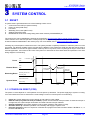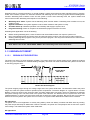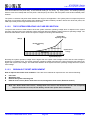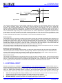
1
SN32F100 Series
32-Bit Cortex-M0 Micro-Controller
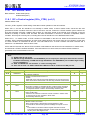
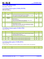
4.3.3.1
Entering Deep power-down mode
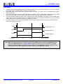
Follow these steps to enter Deep power-down mode from Normal mode:
1.
Pull the DPDWAKEUP pin externally HIGH (Please confirm pull-up time to ensure that the DPDWAKEUP pin
already in the pull-up state).
2.
(Optional) Save data to be retained during Deep power-down to the DATA bits in Backup registers.
3.
Write 1 to DPDEN bit in PMU_CTRL register to enable Deep power-down mode.
4.
Time spent between step 1 and step 5 shall longer than 20 us.
5.
Execute ARM Cortex-M0 WFI instruction.
After step 5, the PMU turns off the on-chip voltage regulator and waits for a wake-up signal from the DPDWAKEUP pin.
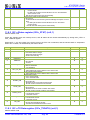
4.3.3.2
Exiting Deep power-down mode
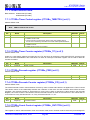
Follow these steps to wake up the chip from Deep power-down mode:
1. DPDWAKEUP pin transition from HIGH to LOW.
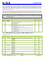
– The PMU will turn on the on-chip voltage regulator. When the core voltage reaches the power-on-reset (POR)
Trigger point, a system reset will be triggered and the chip reboots.
– All registers except the PMU_BKP0 to PMU_BKP 15 and PMU_CTRL will be reset.
2. Once the chip has rebooted, read DPDEN bit in PMU_CTRL register to verify that the reset was caused by a
wake-up event from Deep power-down and was not a cold reset.
3. Clear the DPDEN bit in PMU_CTRL register.
4. (Optional) Read the stored data in the backup registers.
5. Setup the PMU for the next Deep power-down cycle.
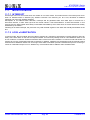
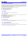
4.4 WAKEUP INTERRUPT
System will exit Deep-sleep mode when GPIO indicates a GPIO interrupt to the ARM core. The all GPIO port pins are
served as wakeup pins. The user must program the registers for each pin to set the appropriate edge polarity for the
corresponding wakeup event. Only edge sensitive is supported to wakeup MCU. Furthermore, the interrupts
corresponding to each input must be enabled in the NVIC.
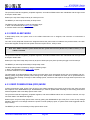
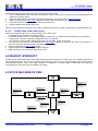
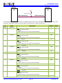
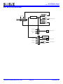
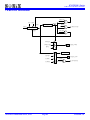
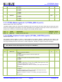
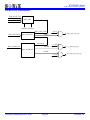
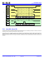
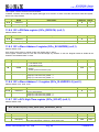
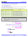
4.5 STATE MACHINE OF PMU
Reset
Wake-up condition
Pulling the DPDWAKEUP pin
LOW
Enter mode condition
1. SLEEPEN = 1
2. WFI instruction
Reset condition
One of reset trigger sources
actives
Enter mode condition
1. Pull High WAKEUP pin
2. DPDEN = 1
3. WFI instruction
Sleep
mode
Run
mode
Deep power-down
mode
Wake-up condition
Interrupt
Wake-up condition
GPIO Wakeup
RTC interrupt
Enter mode condition
1. DSLEEPEN = 1
2. WFI instruction
Reset condition
One of reset trigger sources
actives
Deep-sleep
mode
SONiX TECHNOLOGY CO., LTD
Page 63
Version 1.4