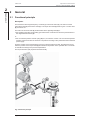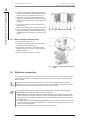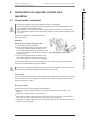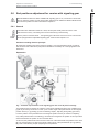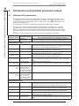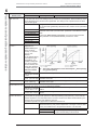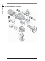
1
Operation instructions Electric actuators SIPOS 5 PROFITRON HiMod Issue 11.15 Subject to changes without notice! Y070.020/GB Contents Operation instructions SIPOS 5 PROFITRON, HiMod Contents 6 Parameters and possible parameter values ............................... 44 6.1 Valve-specific parameters ................... 44 6.2 Control system parameters ................. 46 6.3 Optional software functions ................ 54 7 Status and fault signals, diagnosis ............................................ 55 7.1 Observing (device state and fault signals) ........................................ 55 Sub-assemblies ..................................... 7 7.2 Status and fault signals ...................... 58 2.3 Block diagram (electrical connections) .. 8 7.3 Diagnosis (operational data and maintenance limits) ............................. 61 3 Assembly and connection .................. 9 7.4 Recording the torque curves ............... 62 3.1 Mounting to valve/gear .......................... 9 3.2 Electrical connection ........................... 10 8 Maintenance, inspection, service .... 64 3.3 Separate mounting .............................. 14 8.1 General ................................................ 64 8.2 Lubrication intervals and lubricants ..... 65 4 Instructions on operator control and operation ..................................... 15 9 Spare parts ......................................... 66 4.1 Crank handle, hand wheel ................... 15 9.1 General ................................................ 66 4.2 Local control station, display ............... 16 9.2 Spare parts list .................................... 66 4.3 Main menu, menu control .................... 18 9.3 Exploded views ................................... 67 4.4 Remote control .................................... 20 4.5 COM-SIPOS ........................................ 21 5 Commissioning ................................. 22 5.1 General information ............................. 22 Original Declaration of Incorporation of Partly Completed Machinery (EC Directive 2006/42/EC) and EC Declaration of Conformity in compliance with the Directives on EMC and Low Voltage ..........................79 5.2 Selecting the language ........................ 23 5.3 Accessing the „commissioning“ menu; access authorization ................. 24 5.4 Programming closing direction, speeds, cut-off modes and tripping torques ................................................ 25 5.5 Other valve-specific parameters ......... 29 5.6 End positions adjustment for version with signaling gear ............................... 31 5.7 End position adjustment for HiMod and PROFITRON in „non-intrusive“ version ................................................. 39 1 General information ............................ 3 1.1 Safety information ................................. 3 1.2 Transport and storage ........................... 4 1.3 Disposal and recycling .......................... 4 1.4 Notes to the operation instructions ........ 4 1.5 Supplementary operation instructions ... 5 2 General ................................................. 6 2.1 Functional principle ............................... 6 2.2 Page 2 Y070.020/GB Operation instructions SIPOS 5 PROFITRON, HiMod 1 General information 1 General information 1.1 Safety information General The devices referred to in this document applies are components of installations conceived for industrial applications. They are designed in accordance with the recognized engineering rules. All work involved in transport, assembly, installation, commissioning, maintenance and repair has to be performed by qualified personnel. Qualified personnel within the meaning of the safety instructions of this documentation are all persons authorized to perform the required tasks according to the standards of safety technology and which may recognize and avoid potential hazards. They must be thoroughly familiar with the warnings at the device and the safety instructions of these operation instructions. For work on power installations, the prohibition of the use of non-qualified persons or similar is stipulated in EN 50110-1 (formerly DIN VDE 0105) or IEC 60364-4-47 (VDE 0100 part 470). Correct transport, proper storage, mounting and installation, as well as careful commissioning are essential to ensure a trouble-free and safe operation. The availability of this product is restricted according to IEC 61800-3 and may cause radio interferences in domestic environments. In this case it may be necessary to take additional measures. ■ Leakage The leakage current of the actuators is typically greater than 3.5 mA. Therefore a fixed installation according to IEC 61800-5-1 is required. ■ Residual current circuit breakers or monitoring devices Due to the integrated frequency inverter, a direct current can be induced in the protective earthing conductor. If the network an upstream residual current device (RCD) or residual current monitor (RCM) is used, then it must be of type B. The following is of particular importance: ■ the technical data and information concerning the proper use (installation, connection, ambient and operating conditions) provided in the catalog, order documents, operation instructions, rating plate data and in the other product documentation; ■ the general installation and safety guidelines; ■ the local plant-specific regulations and requirements; ■ the local environmental conditions, in particular the repeated load which might result when mounting the actuator to a vibrating valve. ■ the proper use of tools, lifting and transport equipment; ■ the use of personal protective equipment, especially in high ambient temperatures and with high actuator surface temperatures (caused by frequent and long activation times). Warnings on the device Danger of crushing. When pressing in the crank handle or the handwheel ensure that neither the hand nor the fingers are crushed, refer to figure. Applicable for devices of the 2SA5.5/6/7/8 and 2SB555/6 series. Indicates the lubricant used. Refer also to chapter 8.2 “Lubrication intervals and lubricants“. Fig.: Danger of crushing Y070.020/GB Page 3 General information 1 1 General information Operation instructions SIPOS 5 PROFITRON, HiMod 1 General information 1.2 Transport and storage ■ The dispatch must be performed in sturdy packaging. ■ For transport, loop the rope around the motor and the hand wheel housing, refer to illustration. Only use the eyes (1) on the electronic unit to lift the actuator‘s own weight. ■ Do not attach the ropes and hooks at the crank handle or hand wheel for the purpose of lifting. ■ Store in well-ventilated, dry room. ■ Protect against damp floors by storing on a shelf or pallet. ■ Keep connection hood/cover and cable glands as well as the cover of the electronic unit closed. Fig.: Transport 1.3 Disposal and recycling Packaging The packaging of our products consists of environmentally friendly materials which can easily be separated and recycled. We use following packaging materials: Wood-based panels (MSB/OSB), cardboard, paper, PE foil. For the disposal of the packaging material, we recommend recycling and collection centers. Actuator Our actuators have a modular design and may therefore be easily disassembled, separated and sorted according to materials, i.e.: electronic parts, different metals, plastics, greases and oils. The following generally applies: ■ Collect greases and oils during disassembly. As a rule, these are substances hazardous to water and must not be released into the environment. ■ Arrange for controlled waste disposal of the disassembled material or for separate recycling according to materials. ■ Observe the national/local regulations for waste disposal. 1.4 Notes to the operation instructions 1.4.1 Safety instructions: Used symbols and their meanings The following symbols, which have different meanings, are used in the operation instructions. Nonobservance may lead to serious injuries or property damage. Warning marks activities which, if not carried out correctly, can affect the safety of persons or property. Notice marks activities which have major influence on the correct operation. Non-observance of these notes may lead to consequential damage. Electrostatically endangered are located on circuit boards, which may be damaged or destroyed by electrostatic discharges. If the boards need to be touched during setting, measurement or for exchange, it must be assured that immediately before touching an electrostatic discharge through contact with an earthed metallic surface (e.g. the housing) has taken place. Procedure may have been performed by valve manufacturer: If actuators are delivered mounted to a valve, this step has been done in the valve manufacturer’s factory. The setting has to be checked during commissioning. Page 4 Y070.020/GB Operation instructions SIPOS 5 PROFITRON, HiMod 1 General information 1.4.2 Scope For the sake of clarity, not all details of all versions of the product are described in these operation instructions, nor can they cover all conceivable cases regarding installation, operation and maintenance. For this reason, the operation instructions only contain instructions for qualified personnel (refer to section 1.1) that are necessary when the equipment is used for the purpose for which it is intended or in industrial applications. If the devices are used in non-industrial applications with increased safety requirements, they have to be ensured by additional safety measures during assembly. In case of any questions, and especially where detailed product information is not available, contact the SIPOS Aktorik sales representative in charge. Always state the type designation and the works number of the respective actuator (see rating plate). It is recommended that the services and support of the responsible SIPOS Aktorik service centers are utilized for all planning, installation, commissioning and service task. The contents of these operation instructions and product documentation shall not become part of or modify any prior or existing agreement, commitment or legal relationship. The Purchase Agreement contains the complete and exclusive regulation on material defect liability of SIPOS Aktorik. These contractual regulations are neither amended nor limited by the descriptions contained in these operation instructions and documentation. 1.5 Supplementary operation instructions 2SB5 linear actuator 2SC5 part-turn actuator 2SG5 small part-turn actuator COM-SIPOS computer parameterization software PROFIBUS operation instructions MODBUS operation instructions HART instructions Enclosure protection IP68 „K51“ Increased vibration resistance „K57“, „K58“ Increased vibration resistance according to seismic class S2A „K59“ Very high corrosion protection corrosivity category C5 with long protection time „L38“ SIPOS 5 actuator with USP Binary and analog inputs freely available via bus Optional software functions Short instructions PROFITRON and others Y070.027 Y070.028 Y070.029 Y070.024 Y070.023 Y070.022 Y070.221 Y070.047 Y070.048 Y070.049 Y070.162 Y070.053 Y070.050 See chapter 6.3 Y070.021 Any special installation and operation instructions furnished by the suppliers of subcontracted components, attachments or fixtures are attached to the set of instructions and have to be observed. Y070.020/GB Page 5 General information 1 2 General Operation instructions SIPOS 5 PROFITRON, HiMod 2 General 2 General 2.1 Functional principle Description The electronics with integral frequency converter (1) controls the motor (2). The motor turns the output drive shaft (4) via the worm shaft (3). The output drive shaft (4) drives a gear or a valve stem (5) via a stem nut. The motion of the worm shaft (3) is transferred via the signaling shaft (6) to. ■ the signaling gear (7a). The signaling gear reduces the movement and turns the potentiometer or the magnetic travel sensor (8). or: ■ the non-intrusive position encoder (niP) (7b) for „non intrusive“ version. The non-intrusive position encoder counts the number of rotations. The position recording is also performed without external power supply. From the position of the potentiometer or the non-intrusive position encoder, the electronics recognizes the position of the output shaft (9) and therefore the position of the operated valve. The motor is controlled according to the process requirements. The torque detection (DE) is performed electronically. Fig.: Functional principle Page 6 Y070.020/GB Operation instructions SIPOS 5 PROFITRON, HiMod 2 General 2 Sub-assemblies General 2.2 The actuators of the SIPOS 5-Series comprise two main assemblies: gear unit and electronics unit. For details see chapter 9. „Spare parts“. The main sub-assembly gear consists of the sub-assemblies: 1 Plug element electronic connection, 2 Motor, 3 Gear unit, 4 Signaling gear or non-intrusive position encoder (not for 2SG5) with cover, 5 Manual drive (with crank or hand wheel), 6 Possible mechanical extensions, depending on the version, For the small 2SG5 part-turn actuator, the signaling gear is omitted; gear unit and manual drive have a different shape. Fig.: Sub-assemblies gear The main sub-assembly electronics unit consists of the sub-assemblies: 1 Electrical connection (there are three versions), 2 Plug element gear connection, 3 Electronic housing with cover, 5 Fieldbus board (option) or 6 Relay board (option), 7 Control board , 8 Bluetooth module (option). 4 Power control PCB, including Power module, Fig.: Sub-assemblies electronics unit Y070.020/GB Page 7 2 General Operation instructions SIPOS 5 PROFITRON, HiMod 2 General 2.3 Block diagram (electrical connections) The block diagram shows the electronic sub-assemblies and the inputs and outputs for possible customer-specific connections. Fig.: Block diagram Page 8 Y070.020/GB Operation instructions SIPOS 5 PROFITRON, HiMod 3 Assembly and connection 3 Assembly and connection 3.1 Mounting to valve/gear If actuators are delivered mounted to a valve, this step has been done in the valve manufacturer’s factory. However, the setting has to be checked during commissioning. ■ Please pay attention to the safety information (see chapter 1.1)! ■ Before starting the assembly, please make sure that the intended measures (possible operation of the valve, etc.) is not likely to cause any injuries to persons or to interfere with the equipment. It is recommended that the services and support of the responsible SIPOS Aktorik service centers are utilized for all planning, installation, commissioning and service task. 3.1.1 General assembly instructions for all output shaft versions ■ Mounting and operation is possible in any position. ■ Avoid all shocks; do not attempt to use force. ■ Check that the end connection flange and the output shaft type match the valve/gear. ■ Thoroughly degrease mounting faces at actuator and valve/gear. ■ Slightly grease the connection points. ■ Place the actuator on the valve/gear, making sure it is properly centered. ■ Use bolts with at least 8.8 quality. If other similar, stainless steel bolts are used, they should be greased slightly with petroleum jelly. The depth of engagement should be at least 1.25 x the thread diameter. ■ Position the actuator on the valve/gear and tighten the bolts evenly in diagonally opposite sequence. ■ The housing of the SIPOS 5 actuators consists of an aluminum alloy which is corrosion resistant under normal environmental conditions. If the paint was damaged during assembly, it can be touched up with original paint supplied in small quantity units by SIPOS Aktorik. 3.1.2 Output shaft type A Assembly instruction The stem nut is screwed onto the valve stem by turning the crank handle or the hand wheel. Fitting and removing the stem nut If the stem nut was not ordered with a trapezoidal thread (suffix „Y18“ to ordering number), or if the stem nut is worn and has to be replaced, proceed as follows: Output flange (fig., item 1) does not have to be removed from the rotary actuator! 1. Unscrew centering ring (fig., item 5) from output flange. 2. Take off stem nut (4) together with axial needle-roller assembly and axial bearing washers (3). 3. Remove the axial needle-roller assembly and the axial bearing washers (3) from the stem nut. 4. Only if the stem nut was delivered without thread: Machine a thread in the stem nut (4) (check the concentricity and the axial run-out when it is clamped) and clean it. Y070.020/GB Fig.: Output shaft type A assembly Page 9 Assembly and connection 3 3 Assembly and connection Operation instructions SIPOS 5 PROFITRON, HiMod 3 Assembly and connection 5. Lubricate axial needle-roller bearings and axial bearing washers (3) with ball bearing grease and fit them on the new or machined stem nut (4). 6. Insert stem nut (4) with axial needle-roller assembly into output flange (claws have to engage properly into the groove of the output shaft of the actuator). 7. Screw in the centering ring (5) and tighten it as far as the stop. Make sure the radial seal is inserted correctly (6). 8. Using a grease gun, press ball bearing grease into the grease nipple (2) until lubricant is discharged between the centering ring (5) and the stem nut (4). Fig.: Output shaft type A installed 3.1.3 Mount spindle protection tube 1. Remove fastener (fig., item 1). 2. Check that the extended stem does not exceed the length of the protective tube. 3. Apply sealing compound to the thread and the sealing faces (e.g. 732 RTV from Dow Corning, Munich, Germany). 4. Screw in the spindle protection tube (2). Fig.: Mounting the spindle protection tube 3.2 Electrical connection The components are designed as to ensure that once connected correctly, uninsulated, live parts cannot be touched directly; i.e. protection against electric shock is provided in accordance with IP2X or IPXXB. Dangerous voltages are also present when the motor is at a standstill. Before opening the terminal cover or the connection hood, disconnect the supply voltage from the actuator. Allow 5 minutes for the capacitors to discharge and do not touch any contacts. ■ The supply voltage must always lie within the voltage range specified on the rating plate. ■ Mains cable: Use metal cable glands for mains connection. ■ Signal cable: Use metal cable glands with cable shielding for the connection of the control cable to avoid the occurrence of electronic faults. The signal cable must be shielded and the shield must be fixed or earthed on both sides. Ensure careful connection of the screen within the cable gland! ■ It must be ensured that the cable glands and seals (O-rings) are fitted carefully and correctly in order to guarantee the enclosure protection. For details of the permissible conductor crosssections, see wiring diagram. ■ Cable glands and cables are not included in the scope of delivery. Page 10 Y070.020/GB Operation instructions SIPOS 5 PROFITRON, HiMod 3 Assembly and connection 3 Assembly and connection 3.2.1 Direct connection Fig.: Direct connection Highly sensitive CMOS semiconductor components extremely sensitive to static electricity are mounted on the printed circuit boards. Avoid touching tracks or components on the boards with the fingers and prevent tracks or components coming into contact with metal objects. Only the screws of the terminal blocks may be touched in order to make the connections and only with an insulated screw driver. 1. Unscrew connection hood (fig., item 1) and cover for electronic housing (7). 2. Unscrew screw plugs from the required cable glands in the connection hood. 3. Screw in the cable glands (2) only slightly and insert the connecting cables. 4. Take off terminal plug X1 (4) from the power control PCB and terminal plugs X3.1, X3.2 (6) from the control board. If a relay board is used, then remove terminal plugs X2.1, X2.2 (5). If required, use a screw driver to carefully eject the plugs from the sockets. 5. Connect the connecting cables in accordance with the circuit diagram enclosed in the connection hood, connecting the earth lead conductor to the provided terminal in the connection box. 6. Reconnect all terminal plugs. 7. Fit connection hood (1) and cover for electronic housing (7) again. 8. Tighten cable glands (2). Y070.020/GB Page 11 3 Assembly and connection Operation instructions SIPOS 5 PROFITRON, HiMod 3 Assembly and connection 3.2.2 Connection with round plug 1. Unscrew connection hood (fig., item 2) with plug element (1). 2. Unscrew screw plugs from the required cable glands in the connection hood. 3. Unscrew plug element (1) from connection housing (2). 4. Screw in the cable glands (3) only slightly and insert the connecting cables (4). 5. Connect the connecting cables in accordance with the circuit diagram enclosed in the connection hood, connecting the earth lead to the provided terminal in the connection box. 6. Screw plug element (1) into the connection hood (2) and then fix connection hood. 7. Tighten cable glands (3). Fig.: Connection with round plug 3.2.3 Fieldbus connection 1. Dismantle fieldbus connection housing (fig. item 2) and connection cover (4). 2. Unscrew plug element (1) from fieldbus housing (2). 3. Unscrew screw plugs only from the required cable glands of the fieldbus housing. 4. Screw in the cable glands (5) only slightly and insert the connecting cables (6). For fieldbus cables, cable glands without shield are sufficient, refer to point 7 below. 5. Connect the mains cables and, if required, signal cables in accordance with the circuit diagram enclosed in the connection hood, connecting the earth lead conductor to the provided terminal in the connection box. 6. Fit plug element (1) into fieldbus housing (2) again. 7. Connect fieldbus connecting cables to the bus termination PCB (3). Lead shielding (7) under metal clamp (8). 8. Fit connection cover (4) and fieldbus housing (2) again. 9. Tighten cable glands (5). Fig.: Fieldbus connection a = If the actuator is the last device of the bus segment, the termination resistor must be set to ON or a termination must be done externally. b = Connection for external 24 V power supply. Enables communication even if the mains are disconnected. c = Connection for PROFIBUS DP bus motor (protcol analyzer). Page 12 Y070.020/GB Operation instructions SIPOS 5 PROFITRON, HiMod 3 Assembly and connection 3.2.4 Connection with galvanic separation Binary inputs and outputs are galvanically separated via opto-couplers. Analog signals can be galvanically separated as an option. This is required to avoid overlapping currents and voltages by means of equalization potentials. ■ Actual position value (analog output) galvanically separated: Add. version C10. ■ Actual position value (analog output) and position setpoint (analog input) galvanically separated. Add. version C11. 1. Unscrew fieldbus connection housing (fig., item 2) and connection cover (4). 2. Unscrew plug element (1) from connection housing (2). 3. Unscrew screw plugs from the required cable glands in the connection hood. 4. Screw in the cable glands (5) only slightly and insert the connecting cables (6). 5. Connect the connecting cables in accordance with the circuit diagram enclosed in the connection hood, connecting the earth lead to the provided terminal in the connection box. Connect the wire for analog signals „actual position value“ and, if required, „position setpoint“ to the connection board (3). Lead shielding under the metal clamp. 6. Screw plug element (1) into connection housing (2). Fig.: Connection with galvanic separation 7. Fit connection housing (2) and connection cover (4) again. 8. Tighten cable glands (5). 3.2.5 External potential conductor connection The external potential conductor connection can be used for functional grounding and not for protective grounding. 1. Remove plastic fastener (1) from the electronic housing. 2. Fit potential conductor (4) and gripping disc (3) with M5 screw (2). Fig.: Fitting the potential conductor Y070.020/GB Page 13 Assembly and connection 3 3 Assembly and connection Operation instructions SIPOS 5 PROFITRON, HiMod 3 Assembly and connection 3.3 Separate mounting If the ambient conditions such as extreme vibration, high temperature and/or if access is difficult, the electronics unit is to be mounted separately from the gear. The assembly kit for mounting the gear unit and electronics unit separately can be ordered directly with the actuator or separately as an accessory (2SX5300-.GA..). The assembly kit is preassembled. If the assembly kit is ordered directly with the actuator, it is included separately with the actuator. The assembly kit is also available with a cable separation system with quick disconnect couplers. For installation in separate rooms, a wall bushing of only Ø 45 mm is required. Before starting the work, disconnect actuator from the mains! Procedure 1. Install mounting bracket (fig., item 3) at the mounting location of the electronics unit. 2. Remove electronic housing (1) from the gear unit (6) and mount it on the mounting bracket (3) with the O-ring (2). 3. Standard assembly, refer to A Mount „Separate mounting“ kit: Plug cover with contact pins (4) on lower side of wall bracket (3) and plug cover with contact sockets (5) on the gear unit (6). 4. Assembly with spindle protection tube, refer to B Turn connection hood by 90° or 180° to ensure cables are not impaired by the spindle protection tube. Remove screws (7) from round plug, turn round plug by 90° to 180° and fix screws again. Continue as described in section 3. Fig.: Separate mounting A = Standard, B = with spindle protection tube ■ During installation, it is important to ensure that the O-rings are fitted correctly in order to guarantee the degree of protection. ■ Generally, it has to be ensured that movable parts, e.g those of the swing lever, are not impaired by the cables. ■ In exceptional cases, the motor might become very hot. Therefore the cables should not touch the motor. Specification of the connecting cable between the electronics unit and the gear unit Power supply: Shielded and UV resistant, e.g. Topflex-611-C-Pur-4G1.5/11.3 cable. (TOPFLEX® is a trade mark of HELUKABEL.) Control connection: shielded and UV resistant, e.g. L IY11Y-7x2x0.5/11.4-S. The crimp contacts are silver plated. The connecting cables are available in different versions: ■ Standard lengths: 3 m; 5 m; 10 m, ■ with additional device (filter) up to 50 m (if separate mounting of more than 10 m with filter, the „Sep. mounting“ parameter must be set to value „>10m with filter“). Page 14 Y070.020/GB Operation instructions SIPOS 5 PROFITRON, HiMod 4 Instructions on operator control and operation 4 Instructions on operator control and operation 4.1 Crank handle, hand wheel ■ Motor driven operation of the crank handle/hand wheel is not permitted. ■ After commissioning, the actuator must not be operated beyond the parameterized end positions using the crank handle/hand wheel. ■ When pressing in the crank handle/ the hand wheel, make sure that the hand is not between the crank handle/the hand wheel and the housing: Danger of crushing! See the following operation step 3. During motor operation the crank handle/the hand wheel does not turn. Operation Operation of all actuators except for 2SG5: 1. The actuator must be at standstill (1). 2. Remove the clamp (option) (2). The clamp is used as protection against accidental engaging of the crank handle/the hand wheel, if the actuator is exposed to heavy vibration or water pressure (enclosure Fig.: Operating the crank handle protection IP 68). 3. Press crank handle/hand wheel in direction of the gear housing against the spring force (3) and turn (4). (Caution: Danger of crushing when engaging!) The hand wheel has priority over motorized operation. The actuator can only be operated electrically once the crank handle/hand wheel is released. If the actuator is operated manually in the „Remote“ state and an operation command is present, the actuator is immediately operated after releasing the crank handle. Only for 2SG5: Turn hand wheel without pressing it in. Manual operation interferes with motor operation: If the hand wheel is turned during motor operation, the positioning time is either extended or reduced, depending on the direction of rotation. Direction of rotation Clockwise turning of the crank handle/hand wheel leads to ■ 2SA5 rotary actuator: Clockwise rotation of the output drive shaft (exception: 2SA5.7. and 2SA5.8.). ■ 2SB5 linear actuator: Extension of the thrust rod. ■ 2SC5 part-turn actuator: With view on the pointer cover of the worm gearbox: clockwise movement of the coupling or lever arm with the worm gearbox versions RR or LR. ■ 2SG5 part-turn actuator: With view on the mechanical position indicator: clockwise rotation at the coupling or at the swing lever. Y070.020/GB Page 15 Instructions on operator control and operation 4 4 Instructions on operator control and operation Operation instructions SIPOS 5 PROFITRON, HiMod 4 Instructions on operator control and operation 4.2 Local control station, display On local control station, the operation can be made directly at the actuator via 4 push buttons (refer to fig. Local control panel). By repeatedly pressing the Local/Remote button, you may change between the three states „Remote“, „Local“ and „locPar“. Depending on the state the actuator is in, the push buttons have different functions. If you switch from the „Local“ or „locPar“ to the „Remote“ state, the actuator runs, if there is an operation command present from the automation system. The COM-SIPOS parameterization program enables convenient operation and parameterization of the actuator, refer to chapter 4.5. The actuator can be controlled from the computer (laptop) via a cable or Bluetooth. The communication via Bluetooth is indicated while the LED blinks at the actuator. 4.2.1 Function of the light emitting diodes (LEDs) and function of the push buttons LEDs „Local“ and „Remote“ The light emitting diodes indicate the state of the actuator: ■ ”Remote“: LED Remote (yellow) is illuminated; ■ ”Local“: LED Local (yellow) is illuminated; ■ ”locPar“: LED Local (yellow) is illuminated; LEDs (OPEN) and (ZU) The OPEN LED (green) is flashing if the actuator moves in OPEN direction and is continuously illuminated, if the actuator is in end position OPEN. The same applies to the CLOSE LED (yellow). Function of the push buttons in the local state “Local“ In the „Local“ state, the actuator can be operated locally (OPEN, CLOSED as well as STOP), control from „Remote“ is disabled. Fig.: Local control panel 1 STOP/ENTER push button The STOP/ENTER push button stops the actuator. 2 Local/Remote push button The Local/Remote push button changes between „Remote“ – „Local“ – „locPar“. The selected state is indicated in the display. 3 Push button (OPEN) When pressed, the actuator moves in the OPEN direction. For short operation (< 2 s), the actuator moves as long as the push button is pressed. If the push button is held down for more than 2 seconds, the actuator moves up to the end position once the push button is released or the push button STOP or CLOSE is pressed. 4 Push button (CLOSE) When pressed, the actuator moves in the CLOSE direction. Behavior similar to push button OPEN. Pressing push buttons OPEN and CLOSE at the same time activates the EMERGENCY function: The actuator moves at the parameterized emergency speed/positioning speed/positioning time to the parameterized EMERGENCY position. Page 16 Y070.020/GB Operation instructions SIPOS 5 PROFITRON, HiMod 4 Instructions on operator control and operation 4 In the „Remote“ state, the actuator is controlled by the automation system. If the STOP/ENTER push button is pressed in the „Remote“ state, the following menus can be selected with the or buttons (refer also to chapter 4.3.1, „main menu“) without interrupting the current operation: ■ Language: Selecting another language. ■ com. data r/o: commissioning data; indication of the parameters. ■ Observing: Indication of the device state and possible fault signals. ■ Diagnosis: Indication of the current operational data and maintenance limits. Except for the language, the parameters can only be changed in the „locPar“ state. Function of the push buttons in the „locPar“ state In the „locPar“ state, the parameters can be changed, control from „Remote“ is disabled. If the STOP/ENTER push button is pressed in the „locPar“ state, the following menus can be selected with the or buttons (refer also to chapter 4.3.1 „main menu“): ■ Language: Selecting another language. ■ Commissioning: Changing the parameters (see below). ■ Observing: Indication of the device state and possible fault signals. ■ Diagnosis: Indication of the current operational data and maintenance limits. 4.2.2 Representation of the signals in the display The display indicates the „Remote“, ”Local“ or „locPar“ state the actuator is currently in. Navigation through the menus is supported by the display. The display is automatically illuminated: The backlight is illuminated when pressing a button for the first time, and switches off automatically if no button was pressed for a short time. 1 Display, two lines with 16 characters each and automatic backlight. 2 The valve position, the actuator movement and the direction of the actuator movement are indicated in the first line. In „com. data r/o“, „observing“ and „diagnosis“ menus, the function selected via the or buttons is indicated in the first line. 3 The second line indicates the „Remote“, „Local“ or „locPar“ state and whether the actuator is ready or not. The „com. data r/o“, „observing“ menus show possible parameters, the „diagnosis“ menu the operational data and the maintenance limits. Fig.: Display 4 Parameters and parameter values blinking in the display can be changed via the or buttons and saved with the ENTER button. In chapter 5, „Commissioning“, they are shown in white with black background for operation sequence. 5 Symbol for ENTER button. 6 Symbol for button. 7 Symbol for button. In the following description, those texts in the display which are not relevant to the function described are represented as xxx. Y070.020/GB Page 17 Instructions on operator control and operation Function of the push buttons in the „Remote“ state 4 Instructions on operator control and operation Operation instructions SIPOS 5 PROFITRON, HiMod 4 Instructions on operator control and operation 4.3 Main menu, menu control 4.3.1 Main menu Press the ENTER button to get from the „Remote“ and „locPar“ states to the main menu. The main menu has five menu items: ■ language: Use this command to select another language for the text in the display. ■ com. data r/o: This command can be accessed from „Remote“. The current parameters can be read. Or commissioning: The „commissioning“ menu can only be accessed from the „locPar“ state and after entering the authorization code (4-digit code, see also chapter 5.3). This menu is used to change the Fig.: Main menu actuator parameters. ■ observing: Indication of the devices state and fault signals in the display. Changing the values is not possible. A resettable fault (refer to chapter 7) can however be acknowledged. ■ diagnosis: The operational data and the maintenance limits are indicated. ■ return to menu: The system returns to the initial state. 4.3.2 Scrolling up and down in the main menu Instruction Button Message in the display 1. Set actuator to the „locPar“ or „Remote“ state. In the „locPar“ state, the control is disabled by the DCS. XXX locPar 2. Use the ENTER button to call up the main menu. The first menu ‚Language‘ is indicated. langu./Sprache idioma/lingua E 3. Use the button to scroll down in the main menu. The next menu is displayed. If the main menu was accessed from the „Remote“ operation state, „com.data r/o“ is displayed. commissioning E 4. Scroll down to the next menu. observing E 5. Scroll down to the next menu. diagnosis E 6. Scroll down to the next menu. Press the ENTER button to exit the main menu to the initial state.* 7. Press buttons. The first menu is displayed again. ready return to menu langu./Sprache idioma/lingua E * You can also use the „Local/Remote“ button to exit the menu. However, the actuator does not return to the initial state, but to the next state in the „Remote“ – ”Local“ – ”locPar“ loop. If the main menu was accessed from the „locPar“ state, and if the „Local/Remote“ button is pressed, the actuator changes to the „Remote“ state and starts to move if a control command from the DCS is present! Page 18 Y070.020/GB Operation instructions SIPOS 5 PROFITRON, HiMod 4 Instructions on operator control and operation 4.3.3 Menu control – Navigation and changing the parameter values Access to the menu Use the Local/Remote button to select the following in the display: ■ „Remote“ for reading/observing or changing the language, or ■ „locPar“ for changing the parameter values. Press the ENTER button to activate the selection. Navigation in the menu Operation within the menu always follows the same pattern, see for example “commissioning” menu. 1. Selecting the parameters/scrolling up and down within the menu. Use the or button to select the parameter in the display, fig.: (1) and (5). 2. Activating the selection: Press the ENTER button to activate the selected parameter for changing (2). 3. Changing the parameter value: Press the or button to change the blinking indication (3). 4. Saving the change: Press the ENTER button to save the blinking changed value and return to the menu (4). 5. Select the next parameter (5). Fig.: Navigation in the menu Exit: Exit the parameterization and return to the next higher menu level via the command. Press the or button, until the menu is displayed. return to menu If the „Local/Remote“ button is pressed, the actuator changes to the „Remote“ state and operates if there is an operation command from the DCS! All changes confirmed with the ENTER button are saved. 4.3.4 State indications The actuator state is indicated in the display. Text in display Explanation xx% open xxx xx% open xxx Indicates the opening degree of the set valve travel in percent. The actuator is not in an end position and is in position xx % OPEN. For the HiMod actuator, the opening percentage is displayed with an accuracy of two decimal digits. close The actuator is currently in position xx % and moves in CLOSE direction. The same applies accordingly for OPEN direction. totally closed Actuator is in end position CLOSED. The same applies accordingly for end position xxx OPEN. xxx Remote xxx xxx local xxx xxx locPar Actuator is operated from remote. Actuator can be controlled via the local control station. xxx xxx manual operation Y070.020/GB Actuator is in the parameterization mode. Parameterization of the actuator can be checked and changed. Hand wheel/crank was pressed. Electrical operation of the actuator is not possible if manual operation is active. Page 19 Instructions on operator control and operation 4 4 Instructions on operator control and operation Operation instructions SIPOS 5 PROFITRON, HiMod 4 Instructions on operator control and operation Text in display xxx EM xxx xxx xxx xxx xxx ready fault Explanation Actuator is controlled by EMERGENCY signal. The actuator is ready for operation and can be moved. If this indication is displayed in the „Remote“ or „Local“ state, a fault has occurred: refer to chapter 7, „ Status and fault signals“. The actuator cannot be operated. Note: xxx remote keep Proc xxx remote 4.4 moveT FS This indication will be displayed for all actuators for which the end position adjustment was not yet completed. Only in the „locPar“ state can the actuator be operated via the local control and the necessary parameterizations can be made. The message is only displayed if the „Process controller“ software option is active. Open-circuit behavior from control source (DCS). Actual process value is maintained. The message is only displayed if the „Process controller“ software option is active. Open-circuit behavior from control source (DCS). Fixed process value is approached and maintained Remote control 4.4.1 Control Depending on the automation system and the parameterization for „remote control“ and „remote reconnect“ (refer to chapter 6) is done via ■ conventional connection (24 V binary or 0/4 – 20 mA analog) or ■ Fieldbus (e.g. PROFIBUS DP or MODBUS RTU). Each actuator (device) on the bus is accessed via its bus address. On delivery, the bus address is preset for all devices: 126 for PROFIBUS and 247 for MODBUS, unless ordered otherwise using the programming form, add. version „Y11“. The operation via a fieldbus interface is also described in the separate operation instructions, refer also to chapter 1.5 „Supplementary operation instructions“. The change-over from „Remote“ to „Local“ or „locPar“ can be disabled via fieldbus. An EMERGENCY command sent from the DCS is always executed by the actuator (irrespective of the selected control type and signal source), even if the actuator is conventionally controlled and the EMERGENCY command is sent via fieldbus and vice versa. 4.4.2 Programming and observing Programming and observing from Remote is only possible with fieldbus control. ■ PROFIBUS DP The device parameterization can be read and written via cyclic and acyclic services. A large variety of software tools is available for simple integration. Manufacturer-independent project planning and parameterization tools: – SIMATIC PDM (Process Device Manager). The SIPOS 5 Flash device description EDD (Electronic Device Description) is stored in this parameterization and project planning tool. – FDT/DTM (Field Device Tool/Device Type Manager). The SIPOS 5 Flash device description DTM is available for integration in the parameterization tool FDT. ■ MODBUS RTU The device parameters can be read and written via so called „Holding Registers“ and „Coils“. Observing and diagnosis is possible via „Input-Registers“ and „Discretes Input“. Page 20 Y070.020/GB Operation instructions SIPOS 5 PROFITRON, HiMod 4 Instructions on operator control and operation 4.5 COM-SIPOS The COM-SIPOS parameterization program is a software tool for ■ operation: operation of the actuator in local operation; ■ observing: reading the actuator parameters, the device state in the „Local“ and „Remote“ state; ■ diagnosis: trouble shooting; ■ parameterization: reading and changing the actuator parameters; ■ loading new firmware: software update to the state-of-the-art; ■ archiving: saving of the parameters and torque reference curves of the actuator. The connection between computer and actuator is established via a standard null modem cable or optionally via Bluetooth. COM-SIPOS is available including null modem cable, USB serial adapter and user manual (on CD), ordering number: 2SX5100-3PC02. A Bluetooth interface is available as an option. Y070.020/GB Page 21 Instructions on operator control and operation 4 5 Commissioning Operation instructions SIPOS 5 PROFITRON, HiMod 5 Commissioning 5 Commissioning 5.1 General information ■ Before performing any work on the installed and electrically connected actuator, check with the plant personnel in charge that the commissioning may not cause any fault of the plant or hazards to persons. ■ If a cut-off mode is selected that is not appropriate for the valve, the valve may be damaged! ■ If the current process is canceled with the „Local/Remote“ button during commissioning, the actuator is switched to the „Remote“ state and the actuator moves if an operation command from the DCS is present! ■ There are hazardous voltage levels within the actuator. It is recommended that the services and support of the responsible SIPOS Aktorik service centers are utilized for all planning, installation, commissioning and service tasks. Ensuring prerequisites for commissioning Check and ensure the following points after assembly or during revision and inspection: ■ The actuator is correctly assembled. ■ All fixing screws and connecting elements are firmly tightened. ■ The grounding and equipotential bonding has been correctly implemented. ■ The electrical connections have been correctly implemented. ■ All protection against accidental contact has been implemented for moving or live parts. ■ Neither the actuator nor the valve is damaged. ■ The permitted temperature range for the actuator is maintained and heat dissipation from the final control element is also taken into account. Further checks are also necessary in accordance with the plant-specific conditions. The commissioning steps to be performed in the following sequence are described in detail below You do no have to perform all settings. Depending on whether settings have already been specified when ordering the actuator or whether the actuator was delivered mounted on the valve, checking the settings will be sufficient. 1. Select language. Only required if the text in the display is not shown in the desired language. 2. Access the „commissioning“ menu; access authorization. 3. Program/check closing direction, output speed or positioning speed/positioning time, program/ check cut-off mode and tripping torques/force. If you are already familiar with the operation, you may also continue with chapter 6.1. „Valve-specific parameters“. In this chapter, the parameters and possible parameter values are listed in a table. 4. Check other valve-specific parameters (retry torq.block, rise time, dc-brake, mot. temp. warn., mot. temp. prot., motor heating). 5. Check/adjust end positions. For versions with signaling gear, the signaling gear transmission ratio has to be set before adjusting the end positions. This is only required, if the setting was not specified when ordering the actuator and the default setting does not meet the requirements. 6. Check/set mechanical position indicator, if available. 7. Adapt actuator to the requirements of the automation system. For the parameters for the DCS refer to chapter 6.2. Page 22 Y070.020/GB Operation instructions SIPOS 5 PROFITRON, HiMod 5 Commissioning 5.2 Selecting the language Language selection is only required if the text in the display is not shown in the desired language. At present, the following languages can be selected: Language Text in display Language Text in display German* Sprache DE Polish Jezyk PL English language UK/US Czech jazyk CZ French langue FR Swedish språk SE Spanish Idioma ES Dutch taal NL Italian lingua ITALIANO Portuguese Idoma PT Finnish Kiel FI *Default setting, unless required otherwise by the customer. Operation sequence 1. Select „locPar“ or „Remote“ state. xxx locPar xxx 2. Call up main menu. The language selection menu is displayed. Langu./Sprache/ idioma/Lingua E 3. Confirm selection. The selected language is displayed. language UK/US 4. To change the selection, press the ENTER button. The letters of the selected language are blinking. language UK/US 5. Use the or buttons to select the language. For available languages see table above. Language FR 6. Press ENTER to save the changed language The language selection menu is displayed. Langu./Sprache/ idioma/Lingua E Y070.020/GB Page 23 Commissioning 5 5 Commissioning Operation instructions SIPOS 5 PROFITRON, HiMod 5 Commissioning 5.3 Accessing the „commissioning“ menu; access authorization Parameters can only be changed in the „commissioning“ menu. Access to the „commissioning“ menu is protected by a code. This prevents accidental changing of the parameters. The code is 9044. The code cannot be changed. The „commissioning“ menu is accessed in four steps: 1. Select „locPar“ operation state. 2. Call up main menu. 3. Select „commissioning)“ menu. 4. Access authorization: Enter code 9044. The operation steps are described once in the following. In the following chapters on commissioning, these steps are considered as a prerequisite and will therefore not be described again. Operation sequence 1. Select „locPar“ operation state. xxx locPar xxx 2. Call up main menu. Langu./Sprache/ idioma/Lingua E 3. Select „commissioning“ menu. commissioning E 4. Confirm selection. 0000 is displayed. The first zero blinks. enter PIN-code 0000 h) Press button once. Digit 9 is blinking. enter PIN-code 9000 i) Confirm. The second zero is blinking. Confirm. The third zero is blinking. enter PIN-code 900 00 j) Press button four times. Digit 4 is displayed and blinking. enter PIN-code 904 40 k) Confirm with ENTER, The last zero is blinking. enter PIN-code 9040 0 l) 4 Mal Taste drücken. Ziffer 4 wird angezeigt und blinkt. enter PIN-code 9044 4 m) Confirm with “ENTER”. The display indicates „close direction“ and the current setting in the second line. close direction xxx Now, you can program the closing direction or select other parameters using the change the parameter values. Page 24 buttons to Y070.020/GB Operation instructions SIPOS 5 PROFITRON, HiMod 5 Commissioning 5.4 Programming closing direction, speeds, cut-off modes and tripping torques New actuators are set in the factory. Unless required otherwise by the customer, the default parameters are as follows: ■ clockwise closing direction; ■ cut-off mode in OPEN and CLOSE directions: travel-dependent; ■ tripping torques/forces in OPEN and CLOSE direction: lowest, device-dependent parameter value, for the standard actuator 30 %, for the modulating actuator 50 % of the maximum value (cannot be changed for 2SG5). ■ output speed/positioning speed/positioning time for normal and EMERGENCY operation in CLOSE and OPEN direction: Step 4 of the 7 step parameter range (step-up factor 1.4). If the current parameter settings should be retained, continue with chapter 5.6.3 „Adjusting the end positions“. If you are already familiar with the operation, you may also continue with chapter 6.1. „Valve-specific parameters“. In this chapter, the parameters and possible parameter values are listed in a table. 5.4.1 Selecting the closing direction Unless required otherwise by the customer, the actuators are delivered with clockwise closing direction. If the output drive shaft has to turn counterclockwise in CLOSE direction, the closing direction has to be changed. If the current closing direction is to be retained, continue with chapter 5.4.2. After each change of the closing direction, the end position setting has to be performed again. Operation sequence Detailed description of operation steps 1 to 3, refer to previous chapter 5.3. 1. Change actuator to „locPar“ state. xxx locPar xxx 2. Press ENTER to call up the main menu and press to select „commissioning“. commissioning E 3. Press ENTER button, enter 9044 code and confirm. The selected closing direction is displayed. Default setting is clockwise. close direction clockwise 4. Press ENTER to activate selection. The indication in the second display line is blinking. close direction clockwise 5. Use close direction anti-clockwise or button to change the closing direction. 6. Press ENTER to save the changes. The selection of the closing direction is finished. Now you can press the Y070.020/GB close direction anti-clockwise button to get to the next function. Page 25 Commissioning 5 5 Commissioning Operation instructions SIPOS 5 PROFITRON, HiMod 5 Commissioning 5.4.2 Programming output speeds/positioning speeds/positioning times By programming the output speeds, the speed of the actuator during closing, opening and approaching the EMERGENCY position is determined. Depending on the actuator type, different values for the speed are programmed and indicated in the display: The following parameters are possible: Speed ranges 1,25 – 10 2,5 – 20 5 – 28 5 – 40 10 – 80 20 – 112 20 – 160 1,25 – 10 5 – 40 Speed levels Standard = 4 Speeds in rpm for rotary actuator 2SA5 Possible values for output speed parameter Standard actuator 1,25 1,75 2,5 3,5 5 7 2,5 3,5 5 7 10 14 5 7 10 14 20 28 5 7 10 14 20 28 10 14 20 28 40 56 20 28 40 56 80 112 20 28 40 56 80 112 Modulating actuator 1,25 1,75 2,5 3,5 5 7 5 7 10 14 20 28 1 2 3 4 5 6 10 20 --40 80 --160 10 40 7 Positioning speeds mm/min for linear actuator 2SB5 Positioning speed ranges Possible values for positioning speed parameter 25 – 200 30 – 240 35 – 280 40 – 320 Positioning speed levels: Standard = 4 25 30 35 40 1 35 42 49 56 2 50 60 70 80 3 70 84 98 112 4 100 120 140 160 5 140 168 196 224 6 Positioning times in s/90° for part-turn actuators 2SC5 and 2SG5 Positioning time range Possible values for positioning time parameter 2SC5 160 – 20 160 112 80 56 40 28 2SG5 80 – 10 80 56 40 28 20 14 Positoning time levels: 1 2 3 4 5 6 Standard = 4 200 240 280 320 7 20 10 7 Operation sequence If the actuator is in the „commissioning“ menu, continue with operation step 2. For a detailed description of operation step 1, refer to chapter 5.3 „Access to the commissioning menu.“ 1. Call up the main menu in the „locPar“ state, select „commissioning“ menu and enter code 9044. close direction anti-clockwise 2. Use the button to change to the speed parameter for CLOSE direction. The indication in the display differs depending on the type of actuator: – „closing speed“ for rotary actuator, – „Act. speed cl“ for linear actuator and – ”Act. time cl“ for part-turn actuator. closing speed 28 /min 3. Press ENTER to activate selection. The indication in the second display line is blinking. closing speed 28 /min Page 26 Y070.020/GB Operation instructions SIPOS 5 PROFITRON, HiMod 5 Commissioning 4. Use the or button to change to another value and press ENTER to save the value. closing speed 20 /min 5. Use the button to change to setting of the speed for OPEN direction. The indication differs depending on the actuator type, refer to operation step 2. opening speed 20 /min 6. Press ENTER to activate selection and use tons to change the blinking value. but- opening speed 28 /min 7. Press ENTER to save the selected value. opening speed 28 /min 8. Repeat operation steps 2 to 4 to set the EMERGENCY speed in CLOSE and OPEN directions. em. speed (cl.) 40 /min Now you can press the button to get to the next parameter. 5.4.3 Programming cut-off modes and tripping torques/forces Cut-off mode If the actuator operates, the cut-off mode can be travel-dependent or torque-dependent. Travel-dependent cut-off means, the actuator trips once the valve has reached a defined position. Torque-dependent cut-off means the actuator trips after reaching a pre-defined torque when moving in the end position range. Default value for the cut-off mode of both end positions, OPEN and CLOSED, is travel-dependent. If the current values are to be retained, continue with chapter 5.5. After each change of the cut-off mode, the end position setting has to be performed again. Tripping torque/force The setting (of the tripping torque for the rotary and part-turn actuator, and of the tripping force for the linear actuator) determines for which torque or which force under load the motor trips. This applies to torque/force-dependent tripping in the end position as well as to a block. For this reason, tripping torque or force also have to be set for travel-dependent cut-off mode. The setting range for standard actuators ranges from 30 – 100 % and for modulating actuators from 50 – 100 % in 10 % steps of the maximum torque each (for some part-turn actuators, other limit values apply). Default setting is the lowest possible value (typically 30 % of the maximum value for the standard actuator, and 50 % for the modulating actuator). The following tables show the possible parameter values. For the 2SG5 part-turn actuator, the tripping torque cannot be changed. Y070.020/GB Page 27 Commissioning 5 5 Commissioning Operation instructions SIPOS 5 PROFITRON, HiMod 5 Commissioning Tripping torques in Nm for rotary actuator 2SA5 Possible values for setting in Nm of MDmax Standard actuator 2SA50 9 – 30 9 12 15 18 21 24 27 18 – 60 18 24 30 36 42 48 54 37 – 125 37 50 62 75 87 100 112 75 – 250 75 100 125 150 175 200 225 150 – 500 150 200 250 300 350 400 450 300 – 1000 300 400 500 600 700 800 900 600 – 2000 600 800 1000 1200 1400 1600 1800 1200 – 4000 1200 1600 2000 2400 2800 3200 3600 Tripping torque in %: 30 40 50 60 70 80 90 Default = 30 % Modulating actuator 2SA55 10 – 20 10 12 14 16 18 20 – 40 20 24 28 32 36 40 – 80 40 48 56 64 72 87 – 175 87 105 122 140 157 175 – 350 175 210 245 280 315 350 – 700 350 420 490 560 630 700 – 1400 700 840 980 1120 1260 1400 – 2800 1400 1680 1960 2240 2520 Tripping torque in %: 50 60 70 80 90 Default = 50 % Tripping range Tripping range 3,8 – 7,7 7,7 – 15,4 12,5 – 25 22,5 – 45 45 – 90 76 – 152 Tripping force in % Default = 50 % Tripping forces in kN for linear actuator 2SB5 Possible values for setting in kN of Fmax 3,8 4,6 5,3 6,1 7,7 9,2 10,7 12,3 12,5 15 17,5 20 22,5 27 31,5 36 45 54 63 72 76 91 106 121 50 60 70 80 6,9 13,8 22,5 40,5 81 136 90 Tripping torques in Nm for part-turn actuator 2SC5 Possible values for setting in Nm of MDmax Standard actuator 150 – 250 150 200 250 --------150 – 500 150 200 250 300 350 400 450 330 – 990 330 440 550 660 770 880 990 330 – 1100 330 440 550 660 770 880 990 690 – 1840 690 920 1150 1380 1610 1840 --690 – 2300 690 920 1150 1380 1610 1840 2070 1440 – 3840 1440 1920 2400 2880 3360 3840 --1440 – 4800 1440 1920 2400 2880 3360 3840 4320 Tripping torque in %: 30 40 50 60 70 80 90 Default = 30 % Modulating actuator 175 – 350 175 210 245 280 315 385 – 770 385 462 539 616 693 800 – 1600 800 960 1120 1280 1440 1800 – 3600 1800 2160 2520 2880 3240 Tripping torque in %: 50 60 70 80 90 Default = 50 % 30 60 125 250 500 1000 2000 4000 100 20 40 80 175 350 700 1400 2800 100 7,7 15,4 25 45 90 152 100 Tripping range Page 28 --500 --1100 --2300 --4800 100 350 770 1600 3600 100 Y070.020/GB Operation instructions SIPOS 5 PROFITRON, HiMod 5 Commissioning 5 If the actuator is in the „commissioning“ menu, continue with operation step 2. For a detailed description of operation step 1, refer to chapter 5.3, „Access to the commissioning menu.“ 1. Call up the main menu in the „locPar“ state, select „commissioning“ menu and enter code 9044. close direction clockwise 2. Press button, until “cut-off mode cl.” is indicated in the display. If the indicated parameter value is correct, continue with operation step 6. cut-off mode cl. travel-dependent 3. Press the ENTER button to change the parameter value. The selection is activated. cut-off mode cl. travel-dependent 4. Use the or button to change the parameter value. The indication in the display differs depending on the type of actuator: – „torque-dependent“ for rotary and part-turn actuator, – „travel -dependent“ for linear actuator. cut-off mode cl. torque-dependent 5. Press ENTER to save the change. cut-off mode cl. travel-dependent 6. Press the button to change to the next parameter “Cut-off mode op.” is displayed. Repeat steps 3 to 5 to change the indicated parameter value. If the indicated parameter value is correct, continue with point 7. cut-off mode cl. torque-dependent 7. Press the button to change to the next parameter The display shows the current value of the tripping torque when closing. Repeat steps 3 to 5 to change the indicated value. If the indicated parameter value is correct, continue with operation step 8. max. cl. torque 18 Nm 8. Use the button to change to the torque parameter for the cut-off mode when opening. Repeat steps 3 to 5 to change the indicated parameter value. max. op. torque 18 Nm Now you can press the 5.5 button to get to the next parameter. Other valve-specific parameters The parameters described in this chapter have to be checked and changed, if necessary, during commissioning. The operation sequence for changing the parameters is the same as described for the previous parameters. The parameters and possible parameter values are listed in a table in chapter 6.1 „Valve-specific -specific parameters“. Y070.020/GB Page 29 Commissioning Operation sequence 5 Commissioning Operation instructions SIPOS 5 PROFITRON, HiMod 5 Retry torq.block Commissioning If the actuator is blocked in move (block outside the end position range), the actuator is tripped and a “blocked in move” fault signal is set. The actuator continues to signal „ready“ since it can still be operated into the opposite direction. If the value for the „retry torq.block“ parameter is not equal to zero, the actuator is automatically operated in the opposite direction (for a travel which corresponds to the end position range, but not longer than 2 s) and the back in direction of the block. This happens until the block has been overcome or the programmed number of tries has been reached. Default setting is 0. Rise time The „rise time“ parameter accesses the integral frequency converter. The shorter the rise time the faster the actuator reaches the specified speed. The setting of the rise time influences the modulating behavior. Longer rise times lead to higher modulating accuracy, which reduces the control dynamics at the same time. The setting range (in 0.1 s steps) is 0.1 s to 1 s for standard actuators, 0.1 s to 2 s for modulating actuators. Default setting is 0.5 s. dc-brake A value not equal to „0 %“ triggers the dc brake via the integral frequency converter. The higher the value, the higher the dc braking current is set. For a value of „0 %“, the speed of the motor is reduced as quickly as possible to a standstill via the frequency converter. For nearly all operation points, this is the shortest time to achieve a standstill. We therefore recommend maintaining the default settings. Motor temperature warning A warning is issued once the motor temperature has reached a preset value. A value between 0 and 155 °C can be set. The warning signal can be provided via binary signal and fieldbus protocol. Default value is 135 °C. This parameter is not available for the part-turn actuator 2SG5. Motor temperature protection The motor is equipped with full electronic motor protection against thermal damage. The motor protection is activated in the factory and can be disabled. To prevent accidental disabling, code 9044 has to be entered for acknowledgement. Disabling the motor protection will void the warranty for the motor! Motor heating To prevent condensation while the motor is at standstill, the motor can be heated with DC current when the heater is activated. The heating up depends on the difference between motor temperature and ambient temperature. The heater is switched off as standard. If exposed to strong climatic fluctuations, the actuator should be operated with the motor heater switched on. Page 30 Y070.020/GB Operation instructions SIPOS 5 PROFITRON, HiMod 5 Commissioning 5.6 End positions adjustment for version with signaling gear PROFITRON actuators are either available with signaling gear or as „non-intrusive“ version with the non-intrusive position encoder. End position adjustment for HiMod and PROFITRON with the non-intrusive position encoder is described in chapter 5.7. 5.6.1 General If actuators are delivered mounted to a valve, this step has usually been done in the valve manufacturer’s factory. The setting has to be checked during commissioning. For the part-turn actuator 2SG5…, the signaling gear ratio does not have to be set. The actuator is not equipped with an adjustable signaling gear. Continue with chapter 5.6.3. Position recording function principle By setting the signaling gear ratio and the end positions, it is ensured that the length, as well as start and end of the valve travel (end positions OPEN and CLOSED) are correctly signaled to the electronics. Explanation Fig.: Schematic representation of the signaling gear ratio and end position settings The signaling gear (7) reduces the rotations of the output shaft (4) required for the complete travel [(5) X –Y] to a rotary movement of ≤ 300° (max. rotation angle of the potentiometer or the magnetic position sensor (x - y) (Setting (a), refer to following chapter, „Adjusting the signaling gear ratio“). From the position of the potentiometer or the magnetic position sensor (for reasons of simplicity, only called potentiometer in the following), the electronics recognizes the position of the output drive shaft and therefore the position of the connected valve. To this end, the potentiometer has to be set so that one of the mechanical end positions of the valve (X or Y) corresponds to one limit of the electric setting range of the potentiometer (x or y) (Setting (b), refer to the following chapter „Adjusting the end positions“. Y070.020/GB Page 31 Commissioning 5 5 Commissioning Operation instructions SIPOS 5 PROFITRON, HiMod 5 Commissioning 5.6.2 Adjusting the signaling gear ratio The number of rotations required to cover the whole travel must be known. The data is provided by the valve manufacturer. If this information is not available, see note below. For the required setting of the signaling gear, refer to the „Signaling gear adjustment“ table below. Intermediate values of rev/stroke or travel (mm) or degrees are rounded up to the next incremental value (e.g. for 30 rev/stroke, the incremental value 36 has to be set). Signaling gear adjustment Rotary actuator Linear actuator Part-turn Type 2SA5.1/2/3/4/5/6 2SA5.7/8 Unit Rev/ stroke 2SB551/2 mm/ travel 2SB553 2SB554/5 2SB556 2SC5.1/2/3/4/5/6 Degrees actuator 10 possible settings at the signaling gear (scale) ▬► Valve travel 0,8 0,2 2,1 5,5 0,52 1,37 4 4,8 5,6 6,4 10,5 27,5 70* 180 12,6 33 84* 216 14,7 38,5 98* 252 16,8 44 112* 288 90° * 120/240° ▼ 0,8 ▼ 2,1 ▼ 5,5 14 3,5 ▼ 14 36* 9* ▼ 36 93 23,2 240 60 610 1575 4020 152 393 1005 ▼ 240 ▼ ▼ ▼ 610 1575 4020 465 558 651 744 360° ▼ 93 *Default setting, unless required otherwise by the customer If the number of revolutions per stroke is not known, because, for example, the actuator is to be operated on an available „old“ valve, operate the actuator over the whole travel and note the number of revolutions of the output drive shaft. If it is not possible to watch the output drive shaft, skip this chapter. Observe the note on the signaling gear in the „Prerequisite for end position adjustment“ section in chapter 5.6.3, „Adjusting the end positions“. Procedure 1. Loosen 4 screws (item 1) from the signaling gear cover and remove cover. 2. Round up revolutions/stroke or mm/travel or degrees to the next incremental value (for incremental values refer to table above). 3. Adjust the slide wheel (2) so that the gear rim faces the desired incremental value on the scale: Push the slide wheel in the right direction, applying only little pressure. Adjusting the slide wheel is facilitated by a slight movement of the central wheel (3). Do not yet fit the signaling gear cover. The end positions have to be set and, if available, the mechanical position indicator. Fig.: Adjusting the signaling gear ratio Page 32 Y070.020/GB Operation instructions SIPOS 5 PROFITRON, HiMod 5 Commissioning 5.6.3 Adjusting the end positions The end positions are directly set at the actuator. Prerequisite for end position adjustment ■ The valve must not be jammed. Use the crank handle/hand wheel to release it, if necessary. For the operation of the crank handle/hand wheel refer to chapter 4.1 ■ The signaling gear should be set, refer to previous chapter „Adjusting the signaling gear ratio“. If the signaling gear ratio was not set because the number of revolutions/stroke is not known, proceed nevertheless as described in the following. Observe the message in the display for operation step 10 and proceed accordingly. Initial setting The end positions must not be set according to a specific order. In the following example, the display messages for end position OPEN are shown. The messages for setting end position CLOSED are similar. To cancel the setting procedure, press the buttons simultaneously. Operation sequence If the actuator is in the „commissioning“ menu, continue with operation step 4. For a detailed description of operation step 3, refer to chapter 5.3, „Access to the commissioning menu“. 1. Remove signaling gear cover. 2. Important: Set the central wheel so that arrows 1 and 2 point in upward direction, see illustration on the right. 3. Call up the main menu in the „locPar“ state, select „commissioning“ menu and enter code 9044. close direction clockwise 4. Press button, until ‚endpos. adjust‘ is indicated in the display. endpos. adjust 5. Press ENTER button. The display changes to the first end position. Use the buttons to change between end position CLOSED and OPEN. start withpos.. open 6. Press ENTER button. The display prompts to approach the end position. The second line indicates: – for travel-dependent cut-off mode „press E-button“; – for torque-dependent cut-off mode „until TL reached“. Important: When moving to the end position, observe the direction of rotation of the central wheel. This is important for operation step 8. From firmware version 2.56, an arrow in the display indicates the direction of rotation. move to op.pos. press E-button 7. Depending on whether the cut-off mode for the end position is travel-dependent or torque-dependent, select the following operation sequence. ___________________________ * If an end position setting was already performed (e.g. by the valve manufacturer), the question appears in the display, whether completely new positions have to be set: ”compl. new pos.?“. If not, select the end position which has to be readjusted, refer also to the following chapter 5.6.4 “Readjusting the end positions“. Y070.020/GB Page 33 Commissioning 5 5 Commissioning Operation instructions SIPOS 5 PROFITRON, HiMod 5 Commissioning – Travel-dependent cut-off mode: % open E open + a) Observe the valve position and move the actuator with the OPEN (CLOSE button for setting in CLOSE direction) suntil the valve has reached the end position.* Note: – When pressing the or buttons for a short time (< 2 s), the actuator moves as long as the push button is pressed. When held down for a longer time, the actuator moves, until the STOP (ENTER) button or the button for the opposite direction is pressed. – If the cut-off was torque-dependent due to a block, e.g. in case of a sluggish MOV, an unfavorable torque curve (cancel by pressing the and buttons simultaneously) o this is indicated by“TL-OPEN activ“ or. „TL-CLOSE activ“ in the second line. The same applies to approaching the mechanical end stop (return to the desired end position using the or buttons). b) If the correct position for the end position has been reached, press ENTER to stop the actuator. Perform possibly required fine adjustment with the buttons. move to op.pos. press E-button c) Confirm position with the ENTER button (for 2SG5… continue with step 9.). Symbols in display – „deviation XX“: continue with step 8. – ”deviation 0“: Potentiometer adjustment is OK, continue with operation step 9. adjust of poti deviation XX – Torque-dependent cut-off mode: Hold down OPEN (CLOSE button for setting in CLOSE direction) for more than 2 s! The actuator moves automatically. % open E open + After reaching the end position, the actuator moves shortly in the opposite direction, to return to the end position again (for 2SG5 continue with step 9.). adapting op.pos. busy... Symbols in display – ”deviation XX“: continue with step 8. – “deviation 0”: Potentiometer adjustment is OK, continue with operation step 9. Note: When pressing the or buttons for a short time (< 2 s), the actuator moves as long as the push button is pressed. If the actuator is operated like this, i.e. by pressing the buttons repeatedly for a short time, the cut-off is not travel-dependent. adjust of poti deviation XX ___________________________ * If the actuator has switched off automatically before reaching the end position, two causes are possible: - Sluggish valve resp. adverse torque behaviour, in this case cancel procedure. Press and buttons simultaneously, or - valve has reached the mechanical stop; in this case return to the desired end position, press or buttons. Page 34 Y070.020/GB Operation instructions SIPOS 5 PROFITRON, HiMod 5 Commissioning 8. Slowly turn the central wheel in the same direction1) as it has turned when approaching the end position (see note in operation step 6), until „0“ is shown as „deviation“ in the display. If the central wheel has already reached the stop, turn in the opposite direction. 1 ) From firmware version 2.56, an arrow in the display indicates the direction of rotation: ► = Turn central wheel clockwise. ◄ = Turn central wheel anti-clockwise. Now the potentiometer or the magnetic position sensor are adjusted. adjust of poti deviation 0 If the “ENTER” button is pressed before adjustment to 0, the „adjust of poti – necessary” display appears. If you press „ENTER” again, you return to the start of end position adjustment; „endpos. adjust“ is displayed. 9. Confirm with ENTER. The first end position is set and the system changes to setting the other end position. The second line indicates: – for travel-dependent cut-off mode „press E-button“; – for torque-dependent cut-off mode „until TL reached“. move to cl.pos. until TL reached 10. If the actuator is equipped with a mechanical position indicator, we recommend setting it now. Separate approaching of the end position can thereby be avoided. For the setting, refer to the following chapter 5.6.5. 11. Move the actuator to the other end position: – Travel-dependent cut-off mode % open E close + a) Use the CLOSE button (OPEN button for setting in OPEN direction) to move the actuator, until the valve has reached the end position. Pay attention to the valve during operation. Note: If the cut-off was torque-dependent due to a block, e.g. in case of a sluggish MOV, an unfavorable torque curve (cancel by pressing the and buttons simultaneously), this is indicated by „TL-OPEN activ“ or „TL-CLOSE activ“ in the second line. The same applies to approaching the mechanical end stop (return to the desired end position using the or buttons). b) Once the end position has been reached, confirm after approx. 2 s. with the ENTER button. The display confirms the correct setting. Continue with operation step 12. If „increase it!“ or „decrease it“ is displayed, press the ENTER button and adjust the slide wheel in the signaling gear accordingly (refer to chapter 5.6.2) and repeat the settings of end positions. Y070.020/GB sign. gear ratio adjustment ok! Page 35 Commissioning 5 5 Commissioning Operation instructions SIPOS 5 PROFITRON, HiMod 5 Commissioning – For torque dependent cut-off mode Hold down CLOSE button (OPEN OPEN direction) for more than 2 s! button for setting in adapting cl.pos. busy... The actuator moves automatically until reaching the end position. The actuator moves then shortly in the opposite direction, to return to the end position again. The display confirms the correct setting. If „increase it!“ or „decrease it“ is displayed, press the ENTER button and adjust the slide wheel in the signaling gear accordingly (refer to chapter 5.6.2) and repeat the settings of end positions. 12. Press ENTER button. The actuator changes to the „endpos. adjust“ parameter in the menu. Now set the second end position of the mechanical position indicator, refer to chapter 5.6.5. sign. gear ratio adjustment ok! endpos. adjust Now you can press the button to get to the next parameter. If the Local/Remote button is pressed, the actuator changes to the „Remote“ state. All changes confirmed by ENTER are saved. ■ If the main menu was accessed from the „locPar“ state, and if the „Local/Remote“ button is pressed, the actuator changes to the „Remote“ state and starts to move if a control command from the DCS is present! ■ Once the end positions have been adjusted during commissioning, the central wheel must not be moved! Otherwise a complete readjustment of the end positions is required. 5.6.4 Readjusting the end positions Prerequisites ■ There must be a valid end position adjustment! If not, refer to the previous section „Initial setting“. ■ At the beginning of the end position adjustment, the valve must not be in a jammed state; if necessary, release it by means of the crank handle/hand wheel (see chapter 4.1). ■ Since the initial setting, the position of the central wheel must not be changed and will not be changed during readjustment! Readjustment can be canceled by pressing the and buttons at the same time. The actuator is then ready for use with the original settings. Press the ENTER button, if the „check end-pos.!“, message appears after canceling. Operation sequence 1. Call up the main menu in the „locPar“ state, select „commissioning“ menu and enter code 9044. close direction clockwise 2. Press button, until „endpos. adjust“ is indicated in the display. endpos. adjust 3. Press ENTER button. In the display, the question appears whether completely new positions have to be set.* compl. new pos.? Yes 4. Press button. The display changes to „No“. compl. new pos.? No ___________________________ * The complete end position adjustment is described in the previous chapter. Page 36 Y070.020/GB Operation instructions SIPOS 5 PROFITRON, HiMod 5 Commissioning 5. The display changes to the first end position. Use the buttons to change between end position CLOSED and OPEN. new setting of open 6. Press ENTER button. The first line shows the prompt to approach the selected end position. The second line shows alternatively either the change of travel in % and for – travel-dependent cut-off mode „press E-button“; – torque-dependent cut-off mode „until TL reached“. move to op.pos. Alteration -X,X% 7. Move the actuator to the other end position: – Travel-dependent cut-off mode % open open Alteration -X,X% move to op.pos. press E–button a) Use the OPEN or CLOSE buttons to move the actuator, until the valve has reached the end position. Pay attention to the valve during operation. The change of travel is indicated in the display. Note: If the cut-off was torque-dependent due to a block before reaching the end position, this is indicated by „TL-OPEN activ“ or „TL-CLOSE activ“ in the second line of the display. b) Once the end position has been reached, confirm after approx. 2 sec. with the ENTER button. The display confirms the correct setting. Continue with operation step 8. Note: If the „potentiometer out of range“ or „decrease sign. gear ratio“ is displayed, proceed according to the instructions in the following text „messages“. sign. gear ratio adjustment ok! For torque dependent cut-off mode adapting cl.pos. busy... Hold down OPEN button (CLOSE button for setting end position CLOSED) for more than 2 s. The actuator moves automatically until reaching the end position. The actuator moves then shortly in the opposite direction, to return to the end position again. The display confirms the correct setting. Note: If the „potentiometer out of range“ or „decrease sign. gear ratio“ is displayed, proceed according to the instructions in the following text „messages“. 8. Press ENTER button. The actuator changes to the „endpos. adjust“ parameter in the menu. If required, set the mechanical position indicator, refer to the following chapter 5.6.5. sign. gear ratio adjustment ok! endpos. adjust Now you can press the button to get to the next parameter. If the „Local/Remote“ button is pressed, the actuator changes to the „Remote“ state. All changes confirmed by ENTER are saved. If the main menu was accessed from the „locPar“ state, and if the „Local/Remote“ button is pressed, the actuator changes to the „Remote“ state and starts to move if a control command from the DCS is present! Y070.020/GB Page 37 Commissioning 5 5 Commissioning Operation instructions SIPOS 5 PROFITRON, HiMod 5 Messages: Commissioning „potentiometer out of range“ If the „potentiometer out of range“ message appears, the new end position is not within the available potentiometer range. In this case, cancel the procedure (press and buttons simultaneously). The former setting is valid. If the setting cannot be retained, the end position must be set again. ”decrease sign. gear ratio“ Cancel the procedure if this message appears. The former setting is valid. If the setting cannot be retained, the end position must be set again. 5.6.5 Adjusting the mechanical position indicator The mechanical position indicator indicates the valve position. The green symbol stands for OPEN and the red symbol for CLOSED (refer to illustration). The mechanical position indicator is an option, and not included in all devices. If the actuator was delivered mounted on a valve, the setting may already be performed by the manufacturer. The setting must be checked during commissioning. If the mechanical position indicator was not yet set with the end positions, set the indicator as follows. Fig. 1: Symbols of position indicator Operation sequence 1. Operate the actuator into the end position CLOSED. 2. Remove signaling gear cover. 3. Turn white disc with red symbol (fig., item 2) until the symbol for CLOSED and the arrow (3) are aligned in the indicator glass of the cover. 4. Operate actuator to position OPEN. 5. Hold white disc (2) in position and turn transparent disc (1) so that the green symbol for OPEN and the arrow (3) are aligned. 6. Tighten signaling gear cover. Fig. 2: Adjusting the position indicator Fig. 3: Position indicator for 2SG5 Page 38 Y070.020/GB Operation instructions SIPOS 5 PROFITRON, HiMod 5 Commissioning 5.7 End position adjustment for HiMod and PROFITRON in „non-intrusive“ version PROFITRON actuators are either available with signaling gear or as „non-intrusive“ version with the non-intrusive position encoder (niP). End position adjustment with signaling gear is described in the previous chapter 5.6. If actuators are delivered mounted to a valve, this step has usually been done in the valve manufacturer’s factory. The setting has to be checked during commissioning. 5.7.1 General The end positions are directly set at the actuator. Prerequisite for end position adjustment The valve must not be jammed. Use the crank handle/hand wheel to release it, if necessary. For the operation of the crank handle/hand wheel refer to chapter 4.1. 5.7.2 Initial setting The end positions must not be set according to a specific order. In the following example, the display messages for end position OPEN are shown. The messages for setting end position CLOSED are similar. To cancel the setting procedure, press buttons simultaneously. Operation sequence If the actuator is in the „commissioning“ menu, continue with operation step 2. For a detailed description of operation step 1, refer to chapter 5.3, „Access to the commissioning menu.“ 1. Call up the main menu in the „locPar“ state, select „commissioning“ menu and enter code 9044. close direction clockwise 2. Press button, until ‚endpos. adjust‘ is indicated in the display. endpos. adjust 3. Press ENTER button. The display changes to the first end position.* Use the buttons to change between end positions CLOSED and OPEN. start with pos. open 4. Press ENTER button. The display prompts to approach the end position. The second line indicates: – for travel-dependent cut-off mode „press E-button“; – for torque-dependent cut-off mode „until TL reached“. move to op.pos. press E-button 5. Depending on whether the cut-off mode for the end position is travel-dependent or torque-dependent, select the following operation sequence. * If an end position setting was already performed (e.g. by the valve manufacturer), the question appears in the display, whether completely new positions have to be set: ”compl. new pos.?“. If not, select the end position which has to be readjusted, refer also to the following chapter 5.7.3 “Readjusting the end positions. Y070.020/GB Page 39 Commissioning 5 5 Commissioning Operation instructions SIPOS 5 PROFITRON, HiMod 5 Commissioning ___________________________ * If the actuator has switched off automatically before reaching the end position, two causes are possible: - Sluggish valve resp. adverse torque behaviour, in this case cancel procedure. Press and buttons simultaneously, or - valve has reached the mechanical stop; in this case return to the desired end position, press or buttons. Page 40 Y070.020/GB Operation instructions SIPOS 5 PROFITRON, HiMod 5 Commissioning „busy…“ is then displayed for approx. 4 ° s. During this period, the non-intrusive position encoder is initialized. The first end position is then set and the system changes to setting the other end position. Im Display erscheint „move to cl.pos.“. Depending on the preset cut-off mode of the second end position, the following is displayed in the second line: – for travel-dependent cut-off mode „press E-button“; or – for torque-dependent cut-off mode „until TL reached“. busy… Continue with operation step 6. 6. Move the actuator to the other end position: Depending on whether the cut-off mode for the end position is travel-dependent or torque-dependent, select the following operation sequence. move to cl.pos. REV/STRO 0,0 – Travel-dependent cut-off mode: In the second display line either „press E-button“ or, depending on the actuator type: – REV/STRO for rotary actuator, – STRO [mm] for linear actuator, – < [°] for part-turn actuator, is displayed. move to cl.pos. press E-button a) Use the CLOSE button (OPEN button for setting in OPEN direction) to move the actuator, until the valve has reached the end position. The travel is indicated in the second display line. Pay attention to the valve during operation. Note: If the cut-off was torque-dependent due to a block, e.g. in case of a sluggish MOV, an unfavorable torque curve (cancel by pressing the and buttons simultaneously), this is indicated by „TLOPEN activ“ or „TL-CLOSE activ“ in the second line. The same applies to approaching the mechanical end stop (return to the desired end position using the or buttons). % open REV/STRO b) Once the end position has been reached, confirm after approx. 2 s. with the ENTER button. The display confirms the correct setting. Continue with operation step 7. adjustment ok! – Torque-dependent cut-off mode: In the second display line either „until TL reached“ or, depending on the actuator type: – REV/STRO for rotary actuator, – STRO [mm] for linear actuator, – < [°] for part-turn actuator, is displayed. close 2,1 move to cl.pos. until TL reached Hold down CLOSE button (OPEN button for setting in OPEN direction) for more than 2 s. The actuator moves automatically until reaching the end position. The actuator moves then shortly in the opposite direction, to return to the end position again. adapting cl.pos. busy… The display confirms the correct setting. endpos. adjustm. OK! 7. Press ENTER button. The actuator changes to the „endpos. adjust“ parameter in the menu. Y070.020/GB endpos. adjust Page 41 Commissioning 5 5 Commissioning Operation instructions SIPOS 5 PROFITRON, HiMod 5 Commissioning Now you can press the button to get to the next parameter. If the „Local/Remote“ button is pressed, the actuator changes to the „Remote“ state. All changes confirmed by ENTER are saved. If the main menu was accessed from the „locPar“ state, and if the „Local/Remote“ button is pressed, the actuator changes to the „Remote“ state and starts to move if a control command from the DCS is present! 5.7.3 Readjusting the end positions Prerequisites ■ There must be a valid end position adjustment! If not, refer to the previous section „Initial setting“. ■ At the beginning of the end position adjustment, the valve must not be in a jammed state; if necessary, release it by means of the crank handle/hand wheel (see chapter 4.1). Readjustment can be canceled by pressing the and buttons at the same time. The actuator is then ready for use with the original settings. Press the ENTER button, if the „check end-pos.!“, message appears after canceling. Operation sequence 1. Call up the main menu in the „locPar“ state, select „commissioning“ menu and enter code 9044. close direction clockwise 2. Press button, until ‚endpos. adjust‘ is indicated in the display. endpos. adjust 3. Press ENTER button. In the display, the question appears whether completely new positions have to be set.* compl. new pos.? Yes 4. Press button. The display changes to „No“. compl. new pos.? No 5. Press ENTER button. The display changes to the first end position. Use the buttons to change between end positions CLOSED and OPEN. new setting of open 6. Press ENTER button. The first line shows the prompt to approach the selected end position. move to op.pos. press E–button The second line changes between „change -XX,X%“ and – „press E-button“ for travel-dependent cut-off mode or – „until TL reached“for torque-dependent cut-off mode. move to op.pos. change -100,0% move to op.pos. press E–button ___________________________ * The complete end position adjustment is described in the previous chapter. Page 42 Y070.020/GB Operation instructions SIPOS 5 PROFITRON, HiMod 5 Commissioning 7. Move the actuator to the other end position: – Travel-dependent cut-off mode a) Use the OPEN or CLOSE buttons to move the actuator, until the valve has reached the end position. Pay attention to the valve during operation. The change of travel is indicated in the display. Note: If the cut-off was torque-dependent due to a block before reaching the end position, this is indicated by „TL-OPEN activ“ or „TL-CLOSE activ“ in the second line of the display. b) Once the end position has been reached, confirm after approx. 2 s. with the ENTER button. The display confirms the correct setting. % open change open XX,X% endpos. adjustm. OK! Continue with operation step 8. – For torque dependent cut-off mode Hold down OPEN button (CLOSE button for setting end position CLOSED) for more than 2 s. The actuator moves automatically until reaching the end position. The actuator moves then shortly in the opposite direction, to return to the end position again. The display confirms the correct setting. 8. Press ENTER button. The actuator changes to the „endpos. adjust“ parameter in the menu. adapting op.pos. busy… % open open REV/STRO 48 endpos. adjustm. OK! endpos. adjust Now you can press the button to get to the next parameter. If the Local/Remote button is pressed, the actuator changes to the „Remote“ state. All changes confirmed by ENTER are saved. If the main menu was accessed from the „locPar“ state, and if the „Local/Remote“ button is pressed, the actuator changes to the „Remote“ state and starts to move if a control command from the DCS is present! Y070.020/GB Page 43 Commissioning 5 6 Parameters and possible parameter values Operation instructions SIPOS 5 PROFITRON, HiMod 6 Parameters and possible parameter values 6 Parameters and possible parameter values 6.1 Valve-specific parameters The following table shows the actuator parameters. The sequence matches the structure of the „commissioning“ menu and shows the parameters in the display. Use the and buttons to scroll up and down between these parameters (refer to „Menu control – Navigation and changing of the parameters“ in chapter 4.3.3). In the left column of the table, the parameters are listed with a default value, if available. The next column shows the possible parameter values blinking in the display (you can use the and buttons to scroll up and down between these parameters) and possibly other parameter values. For the possible parameter values for speeds/positioning speeds/positioning times, refer to the tables in chapter 5.4.2; for the possible parameter values for torque (force) limit refer to chapter 5.4.3. On the right, there are possible other parameter values and supplementary explanations. Parameter Default value close direction clockwise Parameter values clockwise anti-clockwise Explanation For a detailed description, refer to chapters 5.4 and 5.5 Direction of rotation of the output drive shaft when closing. If the closing direction was changed, the end positions must be set afterwards. Rotary actuator 2SA5 closing speed Up to 7 steps opening speed Up to 7 steps em. speed (cl.) Up to 7 steps em. speed (op.) Up to 7 steps cut-off mode cl. travel-dependent travel-dependent torque-dependent cut-off mode op. travel-dependent travel-dependent torque-dependent max. cl. torque 30 % 50 % max. op. torque 30 % 50 % Speed in CLOSE direction. Parameterization within the speed range, refer to rating plate 7 levels where each level is 1.4 times higher than the previous one. Speed in OPEN direction. Parameterization identical to speed in CLOSE direction. EMERGENCY speed in CLOSE direction. Parameterization identical to speed in CLOSE direction. EMERGENCY speed in OPEN direction. Parameterization identical to speed in OPEN direction. Cut-off mode in end position CLOSED. If the cut-off mode was changed, the end positions must (!) be set afterwards. Cut-off mode in end position OPEN. If the cut-off mode was changed, the end positions must (!) be set afterwards. Tripping torque in Nm in CLOSE direction. in 10 %-steps: - standard (8 steps) 30–100 % Mdmax - modulating (6 steps) from 50–100 % Mdmax in 10 % steps: Tripping torque in Nm in OPEN direction. - standard (8 steps) 30 – 100 % Mdmax - modulating (6 steps) 50 – 100 % Mdmax Linear actuator 2SB5 Act. speed cl Up to 7 steps Act. speed op Up to 7 steps Act. sp.em.cl Up to 7 steps Act. sp.em.op Up to 7 steps cut-off mode cl. travel-dependent travel-dependent force-dependent Page 44 Positioning speed in CLOSE direction. Parameterization within the positioning speed range, refer to rating plate in 7 levels where each level is 1.4 times higher than the previous one. Positioning speed in OPEN direction. Parameterization identical to positioning speed in CLOSE direction. EMERGENCY positioning speed in CLOSE direction. Parameterization identical to positioning speed in CLOSE direction. EMERGENCY positioning speed in OPEN direction. Parameterization identical to positioning speed in CLOSE direction. Cut-off mode in end position CLOSED. If the cut-off mode was changed, the end positions must (!) be set afterwards. Y070.020/GB Operation instructions SIPOS 5 PROFITRON, HiMod 6 Parameters and possible parameter values Parameter Default value Parameter values cut-off mode op. travel-dependent travel-dependent force-dependent cut-off force cl in 10 %-steps: 50% 50 – 100 % Fmax in 10 %-steps: cut-off force op 50 – 100 % Fmax 50% Explanation For a detailed description, refer to chapters 5.4 and 5.5 Cut-off mode in end position OPEN. If the cut-off mode was changed, the end positions must (!) be set afterwards. Tripping force in kN in CLOSE direction. Tripping force in kN in OPEN direction. Part-turn actuator 2SC5 or 2SG5 Act. time close Up to 7 steps Act. time open Up to 7 steps Act. time em. cl Up to 7 steps Act. time em. op Up to 7 steps cut-off mode cl. travel-dependent travel-dependent torque-dependent cut-off mode op. travel-dependent travel-dependent torque-dependent max. cl. torque 30 % 50 % max. op. torque 30 % 50 % Positioning speed in CLOSE direction. Parameterization within the positioning time range, refer to rating plate in 7 levels where each level is 1.4 times higher than the previous one. Positioning time in OPEN direction. Parameterization identical to positioning time in CLOSE direction. EMERGENCY positioning time in CLOSE direction. Parameterization identical to positioning time in CLOSE direction. EMERGENCY speed in OPEN direction. Parameterization identical to positioning time in CLOSE direction. Cut-off mode in end position CLOSED. If the cut-off mode was changed, the end positions must (!) be set afterwards. Cut-off mode in end position OPEN. If the cut-off mode was changed, the end positions must (!) be set afterwards. Tripping torque in Nm in CLOSE direction. For 2SG5… the tripping torque cannot be programmed. in 10 % steps: - standard (8 steps) 30 – 100 % Mdmax - modulating (6 steps) 50 – 100 % Mdmax in 10 % steps: Tripping torque in Nm in OPEN direction. - standard (8 steps) For 2SG5… the tripping torque cannot be programmed. 30 – 100 % Mdmax - modulating (6 steps) 50 – 100 % Mdmax Rotary actuator 2SA5, linear actuator 2SB5, part-turn actuator 2SC5 or 2SG5 retry torq.block 0 to 5 0 In case of block outside the end position range, the actuator repeatedly moves against the block (1 to 5 times). Parameter value 0 means the position does not have to be approached again. The setting of the rise time influences the modulating behavior. Longer rise times lead to higher modulating accuracy, which reduces the control dynamics at the same time. in 0,1 s-steps - Standard actuator: 0,1 bis 1,0 s - Modulating actuator: 0,1 bis 2,0 s 0 - 250 % A value not equal to „0 %“ triggers the DC brake via the integral frequency dc-brake converter. The higher the value, the higher the DC braking current is set. in 1 % steps 0% For a value of „0 %“, the speed of the motor is reduced as quickly as possible to a standstill via the frequency converter. For nearly all operation points, this is the quickest way to achieve a standstill. We therefore recommend maintaining the default settings. 0 155 °C Warning after the motor temperature has reached the programmed value. mot. temp. warn. Parameterization not available for 2SG5. in 1°-steps 135°C On Disabling the motor protection will void the warranty for the motor. mot. temp. prot. Off On On Depending on the motor temperature, the motor is heated at standstill with motor heating DC current. Off Off rise time 0,5 s start with pos. OPEN; start with pos. CLOSED rec.torque graph rec.torque graph curve no. 1, 2 or 3 endpos. adjust Y070.020/GB The mechanical end positions of the connected valve are adjusted to the positioning range of the actuator, for the setting procedure refer to chapter 5.6.3, respectively 5.7.3 „Setting the end positions“. Up to 3 torque reference curves can be recorded at different times. Diagnosis is enabled by means of comparison. Refer to chapter 7.4 „Recording the torque curves“. Page 45 Parameters and possible parameter values 6 6 Parameters and possible parameter values Operation instructions SIPOS 5 PROFITRON, HiMod 6 Parameters and possible parameter values 6.2 Control system parameters In the following the parameters and possible parameterizations for the process control are listed in a table. The following example shows which information is included in which column. Parameter Default value Explanation This column contains explanations to the parameter on the left. Parameter value The parameters are listed in this column. The normal text marks the default parameters. The possible parameter values are listed here. This column contains explanations to the parameter value on the left. Other param. This column contains explanations to the Here, you can proba- parameterization on the left. bly find other parameterizations. The presentation and the sequence of the parameters match the structure of the „commissioning“ menu and show the parameters in the display. Use the and buttons to scroll up and down between these parameters (refer to chapter 4.3.3, „Menu control – Navigation and changing of the parameters“). Parameter Default value Explanation Parameter value Other param. endpos.range cl. 0% to 2% From [0 % to 2 %] to [0 % to 20 %] in 1 % steps endpos.range op. From [98 % to 100 %] 98% to 100% to [80 % to 100 %] in 1 % steps Fig.: End position ranges Within the end position range, travel is at a low speed (positioning speed or long positioning time). If the actuator trips torque-dependently outside this range, it is recognized as a fault („disabled in move“, refer to chapter 7.2). setpoint input rising, 4-20mA Setpoint for control type „threshold switch“ or „positioner“ option (is included if either B, C, E, G, H or K is entered at position 15). Setpoint at analog input 1. Fig.: Conversion of 0/4 – 20 mA into position setpoint 0 – 100 % for different characteristics for positioner setpoint slope rising slope rising: 20 mA corresponds to 100 % OPEN. setpoint slope falling slope falling: 20 mA corresponds to 0 % OPEN. setpoint range 4 mA – 20 mA setpoint range 0 mA – 20 mA Page 46 Detection of open-circuit behavior is possible (live zero). Detection of open-circuit behavior is not possible (dead zero). Y070.020/GB Operation instructions SIPOS 5 PROFITRON, HiMod 6 Parameters and possible parameter values Parameter Default value binary inputs NO emergency input NO remote control PermCont BinInp Explanation Parameter value Other param. Control of the OPEN, CLOSE and STOP inputs. NO Active for 24 V DC signal. NC Active for 0 V DC signal. Control of the EMERGENCY input. NO Active for 24 V DC signal. NC Active for 0 V DC signal. Depending on the version, the actuator can be controlled from the process control via different control types (binary, analog or via fieldbus). PosCntr CurrInp Positioner with setpoint via analog setpoint input. (The actuator moves the valve proportional to the analog signal 0/4 – 20 mA.) Only for enabled positioner. PosCntr bus inp Positioner with setpoint via fieldbus interface. (The actuator operates the valve proportional to the digital signal.) Only for available fieldbus interface and enabled positioner. tri-threshold Control via analog setpoint input: 0 – 30 % = CLOSE, 30 – 70 % = STOP, 70 – 100 % = OPEN (The actuator moves if an analog signal is present within the OPEN or CLOSE range, until the end position is reached or the signal changes to the STOP range. A direct change of the direction of operation is possible). PermCont BinInp Permanent contact via binary inputs with OPEN and CLOSE commands. (The actuator moves as long as an OPEN or CLOSE signal is present. The actuator stops, if the signal is deactivated, the end position has been reached or the OPEN and CLOSE commands are present simultaneously.) PermCont bus Permanent contact signal via PROFIBUS with OPEN and CLOSE commands. (The actuator moves as long as an OPEN or CLOSE signal is sent. The actuator stops if the commands are deactivated in one of the following telegrams or if the end position has been reached.) Only for available fieldbus interface. PulsCont BinInp Pulse contact signal via binary inputs (OPEN, CLOSE, STOP). (After an OPEN/CLOSE pulse, the actuator operates until a STOP command is present or the end position has been reached. A signal for the opposite direction leads to a direct change of the direction of operation.) Only possible if the „remote reconnect“ parameter is set to „non-active“. two-wire-control Control via the binary input OPEN. (The actuator moves if there is an active signal in OPEN direction, until the end position has been reached. If the signal level is changed, the actuator moves in CLOSE direction.) proportion.conv The actuator is operated proportionally to the length of the pulse on the OPEN/CLOSE binary inputs. (The ratio of the actuator travel to the total travel is identical to the ratio of duration of the operation pulse to the duration of the total positioning time. Δ stroke length of pulse = total stroke total stroke time proportion. bus Y070.020/GB The entire positining time (run time) has to be parameterized to this end. Refer to „proport.run time“ parameter. Only for enabled positioner. The actuator is operated proportionally to the length of the pulse via fieldbus. Only for activated positioner function. Page 47 Parameters and possible parameter values 6 6 Parameters and possible parameter values Operation instructions SIPOS 5 PROFITRON, HiMod 6 Parameters and possible parameter values Parameter Default value Explanation Parameter value Other param. remote reconnect The „remote reconnect“ parameter enables the change-over to a second control mode, to change, non-active e.g. in case of an error, from analog to binary control. As a prerequisite, „PulsCont BinInp“ must not be selected for the „remote control“ parameter. The change-over is performed for an active binary STOP signal. non-active Change-over to a second control mode is not possible. The control mode (parameter) selected via the „remote control“ parameter is active. PosCntr CurrInp For an active binary STOP signal the control mode changes from the PosCntr bus inp. parameter value of the „remote control“ parameter to the selected control mode. tri-threshold PermCont BinInp (If the binary STOP signal is not active, the control mode (parameter value) selected via the „remote control“ parameter is active. PermCont bus two-wire-control non-active PosCntr CurrInp DCS-setpt-custom Selection is only Linear displayed if for remote control (see above) „PosCntr CurrInp“ or „PosCntr bus inp.“ was selected. For the default setting of the setpoint input „rising/falling“, it is possible to adapt the curve and to deviate from the linearity. The actual value feedback is adapted using the Fig.: Two basic interpretations of the DCS setpoint: „Slow opening“ DCS-actvl-custom and „quick opening“ parameter. DCS-setpt-custom Identical to default setpoint curve. Linear LT-Sollw-Anpassg The actual position value (of the actuator) slowly follows the setpoint, see Equal percentage illustration on the left. DCS-setpt-custom The actual position value (of the actuator) precedes the setpoint, see illustration on the right. Quick opening DCS-actvl-custom If the setpoint adaptation has been set to slow or quick opening for the „DCS-setpt-custom“ ActVal=Position parameter, the actual value can be adapted accordingly. DCS-actvl-custom The ACTUAL value signaled to the DCS corresponds to the actuator ActVal=Position position. DCS-actvl-custom The ACTUAL value signaled to the DCS corresponds to the defined ActVal=acc.setpt setpoint. proport.run time Only for remote control with parameter values „proportion.conv“ or „proportion. bus“. autom.determin. A prerequisite for proportional operation is that the positioning time (run time), i.e. the time the actuator requires to cover the whole travel, is known. The time can either be determined by the actuator itself or measured and defined by the user. Proportional operation is supported from firmware version 2.40. autom.determin. Automatic determination of the run time. The run time will automatically be determined after any end position adjustment or changes in the rise time. For this, the actuator has to be operated at least 3 % of the travel. user-defined Different run times for OPEN and CLOSE may be defined. run time CLOSE Possible settings for the positioning time: 5 to 3,276 seconds. Default setting is 60 seconds. run time OPEN Page 48 Y070.020/GB Operation instructions SIPOS 5 PROFITRON, HiMod 6 Parameters and possible parameter values Parameter Default value Explanation Parameter value Other param. Err RemoteSource A control wire interruption is detected for control: keep position - binary inputs with parameterization „NC“ (only for control via permanent or pulse contact), - analog inputs with signal range 4 – 20 mA, - fieldbus control. move to em. pos. When detecting an open-circuit behavior, the position programmed for the „emergency pos.“ parameter is automatically approached. Display shows: emerg. Fault keep position When an open circuit is detected, the current position is maintained. Display shows: remote fault keep proc value Actual process value is maintained. The message is only display if the „Process controller“ software option is active. Refer to Supplementary operation instructions „Process controller“ Y070.035. moveTo FixSetPoi Fixed process value is approached and maintained The message is only display if the „Process controller“ software option is active. Refer to Supplementary operation instructions „Process controller“ Y070.035. close tightly Yes Yes Fig.: Close tightly No emergency pos. 0 % 0 % to 100 % in 1% steps inter.cont.CLOSE torque-dependent: 0% to 2% travel-dependent 0% to 0% inter.cont.OPEN torque-dependent: 98% to 100% travel-dependent 100% to 100% From [0 % to 0 %] to [0 % to 100 %] in 1 % steps If the „close tightly“ function is active, closed-loop control within the end position ranges is not possible. If, within a end position range, the operation command in direction of this end position is canceled or a STOP signal sent, the actuator continues its operation until a torque-dependent cut-off occurs or a command in the opposite direction is issued. Even for „travel-dependent cut-off mode“ and for control via positioner or process controller, similar to torque-dependent cut-off mode, the internal operation command is extended until the end position (0 % or 100 %) is reached. This setting is required, if closed-loop control is to be applied within the end position ranges. When the emergency command is active or an open circuit is detected and if the “open circ. beh”. parameter is set to “move to em. pos.”, the position set is automatically approached. With the „inter.cont.CL“ parameter, a signal is sent to the process control, if the actuator is within the programmed travel range. The signal is active from 0 % to the programmed value. From With the „inter.cont. OPEN“ function, a signal is sent to the process control, [0 % to 100 %]to if the actuator is within the programmed travel range. [100 % to 100 %] The output signal is active from the programmed value to 100 %. in 1 % steps Y070.020/GB Page 49 Parameters and possible parameter values 6 6 Parameters and possible parameter values Operation instructions SIPOS 5 PROFITRON, HiMod 6 Parameters and possible parameter values Parameter Default value Explanation Parameter value Other param. act. val. output Actual value output signals the position of the actuator as an analog signal. Pos, rising, 4mA act. value slope 20 mA corresponds to 100 % OPEN rising slope 0/4 mA corresponds to 0 % OPEN act. value slope 20 mA corresponds to 0 % OPEN falling slope 0/4 mA corresponds to 100 % OPEN act. value range Detection of open-circuit behavior is possible 4 mA – 20 mA (live zero). act. value range Detection of open-circuit behavior is not possible 0 mA – 20 mA (dead zero). binary output 1 All in all 8 signaling outputs are available for the binary feedback signal of the actuator to the tot. opened ,NO process control. Each of these outputs can be deactivated or assigned one of 18 status messages available. non-active Signaling output 1 is not assigned a possible status message. ”binary output 1“ is deactivated. One of the following states can be signaled: tot. closed The actuator has cut off in the CLOSED end position. tot. opened The actuator has cut off in the OPEN end position. TL-CLOSE The actuator has cut off torque-dependently in the CLOSE direction. TL-OPEN The actuator has cut off torque-dependently in the OPEN direction. TL-CL or OP The actuator has cut off torque-dependently in the CLOSE or OPEN directions. fault A fault has occurred (for the type of fault refer to chapter 7). blinker The actuator operates. ready The actuator can be operated from „Local/Remote“. ready+remote The actuator can be operated from „Remote“. local The actuator is in “Local” or “locPar” mode. inter.cont.CL The actuator position is within the range from 0 % to the position programmed with the „inter.cont.CLOSE“ function. inter.cont.CL The actuator position is within the range from the position programmed with the „inter.cont.OPEN“ function to 100 %. MotTempFault The max. motor temperature (155 °C) has been exceeded. MotTempWarn The motor warning temperature has been exceeded (not for 2SG5…). ExtVoltFault Low voltage or excessive voltage has been detected, or power supply has been failed. maintenance A maintenance limit has been exceeded. Run.ind.close The actuator operates in direction CLOSE. Run.ind. open The actuator operates in direction OPEN. output state 1 Active high, i.e. 24 V DC if signal is active. NO output state 1 Active low, i.e. 0 V if signal is active. NC binary output 2 tot. closed ,NO binary output 3 TL-OPEN ,NC binary output 4 TL-CLOSE ,NC binary output 5 fault ,NC Parameterization in accordance with „binary output 1“, “output state 1“ binary output 6 local ,NO binary output 7 blinker ,NO binary output 8 MotTempWarn ,NC for 2SG5… : MotTempFault Page 50 Y070.020/GB Operation instructions SIPOS 5 PROFITRON, HiMod 6 Parameters and possible parameter values Parameter Default value Explanation Parameter value Other param. Parameters for the communication with fieldbus PROFIBUS address Only for available Profibus interface. channel 1: 126 For the details, refer to the Profibus operation instructions (refer to chapter 1.5 „Supplementary instructions“). channel 1: 0 Fieldbus address of the actuator on channel 1. to channel 1: 126 PROFIBUS address Only for available redundant Profibus interface. channel 2: 126 For the details, refer to the Profibus operation instructions (refer to chapter 1.5 „Supplementary instructions“). channel 2: 0 Fieldbus address of the actuator on channel 2. to channel 2: 126 PZD 3 Parameter no. .. In the „PPO2“ process representation, four process data values (PZD) can PZD 4 Parameter no. .. be fed with data from the actuator. The parameter numbers entered under PZD 5 Parameter no. .. PZD 3 to 6 are valid for both channels 1 and 2. PZD 6 Parameter no. .. MODBUS address Only for available Modbus interface. channel 1: 247 For the details, refer to the Modbus operation instructions (refer to chapter 1.5 „Supplementary instructions“). channel 1: 1 to Fieldbus address of the actuator on channel 1. channel 1: 247 The following communication parameters, i.e. baud rate, parity and connection control time must match those of the DCS (master). MODBUS baudrate1 Communication parameters on channel 1: 19200 Baud 300, 600, 1200, 2400, Baud rate in bits per second. 4800, 9600, 19200, 38400 Par/Stop MODBUS1 none 2 stopbits No parity and 2 stop bits. gerade 1 Stopbit even 1 stopbit Even parity and 1 stop bit. odd 1 stopbit Odd parity and 1 stop bit. Connection control time. MODBUS moni.time 0,1 to 25,5 s channel 1: 3 s MODBUS address Only for available redundant Modbus interface. channel 2: 247 channel 2: 1 Fieldbus address of the actuator on channel 2. to channel 2:247 Settings same as for Modbus channel 1 address. The following communication parameters, i.e. baud rate, parity and connection control time must match those of the DCS (master). Baudrate MODBUS2 Communication parameters on channel 2: 19200 Baud 300, 600, 1200, 2400, 4800, 9600, 19200, 38400 MODBUS par/stop2 none 2 stopbits even 1 stopbit even 1 stopbit odd 1 stopbit MODBUS moni.time 0,1 to 25,5 s channel 2: 3 s Y070.020/GB Baud rate in bits per second. No parity and 2 stop bits. Even parity and 1 stop bit. Odd parity and 1 stop bit. Connection control time. Page 51 Parameters and possible parameter values 6 6 Parameters and possible parameter values Operation instructions SIPOS 5 PROFITRON, HiMod 6 Parameters and possible parameter values Parameter Default value Explanation Parameter value Other param. Parameters for maintenance, plant identification number and software functions Maintenance parameters enable effective planning of valve maintenance intervals depending on the number of starts performed or the operating hours, for example. For information on actuator maintenance, refer to section 8 „Maintenance, inspection, service“. maintenance Indication is only displayed in the „locPar“ state. Confirming with ENTER leads to an update of the maintenance limits and is indicated with „maintenance – confirmed!“ for a short time. A confirmation should be entered every time that maintenance has been confirming done and also whenever the maintenance interval values are changed, e.g. during initial commissioning. This resets an applied „maintenance“ signal. confirmed! The message is only displayed in the „locPar“ state for a short time once the maintenance has been confirmed with ENTER. not necessary The message is only displayed in the „Remote“ state in the „Diagnosis“ menu if none of the possible maintenance limits has been reached. necessary The message is only displayed in the „Remote“ state in the „Diagnosis“ menu if one of the possible maintenance limits has been reached. In addition, the „maintenance“ signal is displayed. maintenance per After pressing the ENTER button, the „switching cycles“, „torque cut-offs“ and „motor oper.hours“ parameters can be changed one after the other. Changes made to the maintenance interval do E not take effect until the „maintenance – confirming“ parameter has been confirmed. switching cycles Modulating: 30,000 to After reaching the programmed number of cycles Standard: 30.000 30,000,000 by 30,000 the „maintenance“ signal is generated. Modulating: each 10,000,000 Standard: 10,000 to 10,000,000 by 100 each After reaching the programmed number of torquetorque cut-offs Modulating: 200 to Standard: 3.000 20000 by 200 dependent cut-offs, the „maintenance“ signal is Modulating: each Standard: 100 to generated. 10,000 10000 stufenweise by 100 each. motor oper.hours 5 h to 2500 h by 5 After reaching the programmed number of motor 2,500 each. operation hours, the „maintenance“ signal is generated. return to menu Return to „maintenance per.“ parameter actuat.Tag 1-10 Actuator plant identification number, used for plant identification. Entry: Use the and buttons to select alphanumerical characters and confirm with ENTER. The next data digit blinks and can be programmed. Exit setting menu: Press ENTER after entering position 10. Change-over to the next function: Press or buttons. actuat.Tag 11-20 See actuat. Tag 1-10. Optional software functions The software functions listed in the following are already included in the actuator if they were part of the order. The software functions can also be released at a later date. Each software function requires a PIN code which is available as an accessory (also refer to the following chapter „Optional software functions“). enable ProcCntr The operation sequence for enabling the software functions is always the same and therefore described as an example for the following software function. „Process controller“ enabled Function is enabled. disabled Page 52 Function is disabled. Press ENTER to enable the function. enable ProcCntr Enter enable code in the same way as the code for 0000 access authorization, chapter 5.3. Y070.020/GB Operation instructions SIPOS 5 PROFITRON, HiMod 6 Parameters and possible parameter values Parameter Default value enable PosCntr Explanation Parameter value Other param. „Position controller“ customer variant Customer-specific software programming deviating from standard firmware.. 0 Unauthorized setting of customer variants can lead to damage of the actuator/valve/plant! The customer-specific software programming is described in the supplementary operation instructions and is part of the delivery. Digit indication A digit other than 0 indicates a customer-specific software version. enable sp. setp. „External analog output speed setpoint“. enable n curve „Travel-dependent output speed adjustment“. en. prop / split „Proportional/split range function“. en.PosTimeCurve „Travel-dependent freely settable positioning times“. Sep. mounting Parameter for separate mounting. Parameter is important for fault-free operation of the actuator! For incorrect setting, a block might not be detected and the actuator switches off for lower torque None or <= 10 m Setting if no separate mounting or separate mounting of less than 10 m is used. >10m with filter Setting for separate mounting of more than 10 m with LC filter. return to menu Press ENTER to return to the „commissioning“ menu. Y070.020/GB Page 53 Parameters and possible parameter values 6 6 Parameters and possible parameter values Operation instructions SIPOS 5 PROFITRON, HiMod 6 Parameters and possible parameter values 6.3 Optional software functions ■ Positioner (for the description, refer to these operation instructions), order no.: 2SX5200-3FC00** Type: 2S . 5 . . . - . . . . . -4 . B . For HiMod, the „positioner“ software function is included in the scope of delivery. ■ Process controller (PI controller), order no.: 2SX5200-3FG00** Type: 2S . 55 . . - . . . . . -4 . C/L . Supplementary operation instructions Y070.035 from firmware version 2.20 ■ Travel-dependent output speed adjustment (speed curve)*, order no.: 2SX5200-3FD00** Type: 2S . 5 . . . - . . . . . -4 . D/E . Supplementary operation instructions Y070.034 from firmware version 2.14 ■ External analog speed setpoint*, order no.: 2SX5200-3FE00** Type: 2S . 5 . . . - . . . . . -4 . F/G . Supplementary operation instructions Y070.033 from firmware version 2.34 ■ Positioner with proportional/split range function, order no.: 2SX5200-3FH00** Type: 2S . 55 . . - . . . . . -4 . H . Supplementary operation instructions Y070.031 from firmware version 2.34 ■ Travel-dependent freely adjustable positioning times, order no.: 2SX5200-3FJ00** Type: 2S . 5 . . . - . . . . . -4 . J/K. Supplementary operation instructions Y070.032 from firmware version 2.37 * - Output speed for rotary actuator 2SA5 . . .; - Positioning speeds for linear actuator 2SB5 . . . ; - Positioning time for part-turn actuator 2SC5 . . . /2SG5 . . . ** Order number for subsequent enabling of the software function. Always state the works number of the actuator when ordering the optional software functions at a later date. The works number is indicated on the rating plate of the electronics unit (refer to illustration) and can also be viewed via the ► observing works number menu. If the control board was exchanged, the works number of the new control board is not identical with the number on the rating plate. When ordering the software function, always state the number displayed in the „observing“ menu. The enabling of an optional software function is described in the previous chapter. If a later firmware version is required for a software function, the firmware can be downloaded from the SIPOS website www.sipos.de. The firmware update of the actuator is performed with the COM-SIPOS parameterization software. During a firmware update, the actuator parameters (customer settings and work parameters) including end position Fig.: Rating plate setting and operational data are not changed. Page 54 Y070.020/GB Operation instructions SIPOS 5 PROFITRON, HiMod 6 Parameters and possible parameter values 7 Status and fault signals, diagnosis 7.1 Observing (device state and fault signals) Via the „observing“ menu, the device state and the fault signals can be viewed in the display. Changing the values is not possible, however any occurring „fault signal“ can be reset. The following table shows the parameters and the respective messages in accordance with the structure of the „observing“ menu and shows the indications in the display. The left column of the table lists the functions between which can scroll up and down using the and buttons (refer to chapter 4.3.3, „Menu control – Navigation and changing of the parameters“). The next column shows the possible messages. The explanations are on the right. Parameter state of unit E former errors E fault signal TL switch Messages Explanation The actuator is ready for operation can be operated from „Remote“. (However, the „blocked in move“ fault may have occurred.) The actuator is not ready for operation. (Indication also appears, if actuator is operated by hand.) Possible fault messages are displayed one after the other using the button. For the explanation and the possible remedy, refer to next chapter 7.2. return to menu Use ENTER to return to the „state of unit“ function. The former five errors are displayed (former errors 1-5), which can consist of several fault messages each. former errors 1 blocked in move Possible indication for the last fault which has E bus comm. fault occurred (former errors 1), consists of 2 fault messages in this case. return to menu Return to „former errors 1“. former errors 2 former errors 3 Same as for former errors 1. former errors 4 former errors 5 return to menu Return to ”former errors“. reset If a fault occurs, you can try to reset the fault with the ENTER button; The „is reset!“ message is displayed for a short time and then „reset“ again. Only faults which can be acknowledged, such as „runtime error“ are deleted. If there are no other faults, the actuator returns to the „ready“ state. This is indicated by „ready – Yes“ once the „state of unit“ function has been selected. is reset! ndication appears only shortly after pressing the ENTER button. The message indicates that faults which can be acknowledged, were deleted. TL sw. non-act. Tripping torque/force not reached. TL-OPEN activ Torque (force) limit in OPEN direction reached. TL-CLOSE activ Torque (force) limit in CLOSE direction reached. ready Yes ready No Y070.020/GB Page 55 Parameters and possible parameter values 6 7 Status and fault signals, diagnosis Operation instructions SIPOS 5 PROFITRON, HiMod 7 Status and fault signals, diagnosis Parameter remote cntr by Messages PrCntr CurrInp PrCntr bus inp PrCntr fix setp. PosCntr CurrInp PosCntr bus inp. tri-threshold PermCont BinInp PermCont bus PulsCont BinInp two-wire-control proportion. conv proportion. bus inter.cont.CLOSE ...%, activ ...%, non-activ inter.cont. OPEN ...%, activ ...%, non-activ ... % setpoint proc. act. value ... % Analog input 1 ... % Analog input 2 ... % binary inputs CL OP STOP EM no signal motor temperat. ...°C max 155°C ...°C electronics temp 0 actual speed /min 0 mm/min curr. act. Speed 0 s curr. act. time enabled disabled proc. Controller enabled disabled an. speed setpt. enabled disabled enabled speed curve disabled enabled prop / split disabled pos. time curve enabled position cntr Bluetooth disabled valid Explanation Process controller with setpoint via analog process setpoint input. Process controller with setpoint via fieldbus. Process controller with fixed setpoint. Positioner with setpoint via analog setpoint input. Positioner with setpoint via fieldbus. Control via analog setpoint input: 0 – 30 % = CLOSE, 30 – 70 % = STOP, 70 – 100 % = OPEN. Permanent contact signal via binary inputs with OPEN and CLOSE commands. Permanent contact signal via fieldbus with OPEN and CLOSE commands. Pulse contact signal via binary inputs (OPEN, CLOSE, and STOP). Control via OPEN input. Proportional operation conventionally via binary inputs. Proportional operation via fieldbus. The actuator is within the range 0 % to ... % of the travel. The actuator is not within in the range 0 % to ... % of the travel. The actuator is within in the range ... % to 100 % of the travel. The actuator is not within in the range ... % to 100 % of the travel. The current setpoint value is ... % of the set analog signal range, or of the standard for fieldbus control. The current process actual value is ... % of the analog signal range of the sensor. (Indication only appears if the process controller is enabled.) The current value is ... % of the set analog signal range. (position setpoint, process setpoint or connected external sensor.) The current value is ... % of the set analog signal range. (output speed setpoint, actual process value or connected external sensor.) CLOSE, OPEN, STOP and EMERGENCY signals active. (Only active signals are displayed.) CLOSE, OPEN, STOP and EMERGENCY signals not active. The current motor temperature = ... ° C. (not for 2SG5…). Temperature within electronics unit housing. Current output speed. Indication only appears for rotary actuator. Current positioning speed. Indication only appears for linear actuator. Current positioning time. Indication only appears for part-turn actuator. Positioner is enabled (option). Positioner is not enabled. Process controller is enabled (option). Process controller is not enabled. External analog output speed setpoint is enabled (option). External analog speed setpoint* is not enabled. Travel-dependent output speed adjustment* is enabled (option). Travel-dependent output speed adjustment* is not enabled. Proportional/split range function is enabled (option). Proportional/split range function is not enabled. Travel-dependent freely adjustable positioning times are enabled (option). Travel-dependent freely adjustable positioning times are not enabled. Bluetooth module detected. Display appears only if Bluetooth is available. ___________________________ * Output speed is synonymous to positioning speed (linear actuator 2SB5…) and positioning time (part-turn actuator 2SC5…/2SG5…). Page 56 Y070.020/GB Operation instructions SIPOS 5 PROFITRON, HiMod 7 Status and fault signals, diagnosis Parameter Messages Non-intrusive valid motor warranty valid not valid REV/STROKE Travel STROKE [mm] Explanation Display appears only for actuator with non-intrusive position encoder. Opening the housing is not required. The motor protection is not disabled. The motor temp. protection was switched off, the motor can be operated beyond its temperature limit. The warranty for the motor has expired. X.X Indication only appears for non-intrusive actuator. Travel in revolutions per stroke for rotary actuator, travel in mm for linear actuator, swivel range in degree for part-turn actuator. < [°] 2S.5………… MLFB-No. Order number of the actuators (16 digits). ............. 13-digit number of the electronics unit for the manufacturer identification of the actuator, e.g. 6011206001011. ............. 13-digit works number of the originally delivered electronics unit (only relevant for exchange). When delivering an actuator, works number and original works number are identical. 2 . . dd.mm.yy Version number of the firmware, e.g. 238 28.06.07: ► Version 2.38 dated 28.06.2007. . . . V Current dc link voltage of the converter in V. works number orig. works no. firmware CU d.c.link-voltage . motor current Motor current in A. For Profibus control PB source PB channel: or PB channel: no channel act. Actuator is not controlled via Profibus interface. channel 1 activ Actuator is controlled via channel 1 of the Profibus interface. channel 2 activ Actuator is controlled via channel 2 of the Profibus interface. 1 no transmission 2 1,5 Mbaud state PB chan. 1 Wait Prm or state PB chan. 2 wait cfg data exchange No transmission. Communication with 1.5 Mbaud. Waiting for parameterization telegram. Waiting for configuration telegram. Cyclic data exchange with Profibus master. For Modbus control MB source no channel act. Actuator is not controlled via Modbus interface. channel 1 activ Actuator is controlled via channel 1 of the Modbus interface. channel 2 activ Actuator is controlled via channel 2 of the Modbus interface. state MB chan. 1 no communication or state MB chan. 2 baud rate OK data exchange return to menu Y070.020/GB No communication. Set communication parameters are ok. Cyclic data exchange with Modbus master. Press ENTER to return to the „observing“ menu. Page 57 Status and fault signals, diagnosis 7 7 Status and fault signals, diagnosis Operation instructions SIPOS 5 PROFITRON, HiMod 7 Status and fault signals, diagnosis 7.2 No Status and fault signals Message Explanation Possible remedy 21 act. val. error 4 Fault at 0/4 – 20 mA output. 31 blocked in move 2,3 ■ Check valve and torque setting, increase A blockage of has been detected in the travel. The actually required torque exceeds tripping torque if necessary or use the the tripping torque, ”Move again if blocked in move“ function! oder ■ Check MOV for sluggishness. „Separate mount.“ parameter is set to ■ Check „Sep. mounting“ parameter. „>10m with filter“ although there is no LC- Note: The actuator can still be moved elecfilter available.. trically in the opposite direction. A communication error is detected in the Voltage OFF-ON. If the message is still Bluetooth module. The actuator still is ready displayed, replace electronics unit for operation and can be programmed using (Bluetooth board defective). the loal control station or COM-SIPOS via the null modem cable. In fieldbus communication, an interruption Check bus communication and connection. has occurred (timeout). This error status is only signaled as a fault, if the remote control is performed via fieldbus. Note: The bus address must deviate from the default setting (126 for Profibus and 247 for Modbus)! ■ End position setting has not yet been Perform end position adjustment once again. performed, ■ End position was passed due to handwheel operation, ■ Friction coupling of the signaling gear was twisted or the signal gear reduction was changed or ■ Cut-off type was changed (e.g. from torque-dependent to travel-dependent). ■ No complete commissioning or Check settings and change, if required. ■ fault while saving commissioning data caused by main-power fault. Commissioning via fieldbus is active. In this Wait for termination of commissioning via case, programming via the local control bus. station is not possible. DualPortRAM fault. Replace electronics. (Profibus PCB defective.) 16 Bluetooth fault 17 bus comm. fault 2 check end-pos.! 1 2 10 check parameters 4 com. via bus 18 DPR error 2 1 4 25 EEPROM error EEPROM error. 4 Replace electronics. Replace electronics. 12 ElectrTmp fault2,4 Electronics temperature cannot be determi- Einstellungen prüfen und ggf. ändern. ned, value of the electronics temperature is set to 0 ° C. 19 ext.volt. fault1 Mains failure/too low. Check power supply. 15 fault anal inp.2,1 This message is only possible for (4 – 20 mA) live-zero setting. Threshold I: > 21 mA or < 3.6 mA. 2,4 13 Fault I2C No I2C communication possible. 14 Fault I2C niP 3 handwhl. pressed Page 58 No I2C communication possible. 2,4 1 ■ Hand wheel/crank handle is pressed. ■ Cable to the hand wheel is defective. check input current! Voltage OFF-ON. If the message is still displayed, replace electronics unit. (Control board defective) Voltage OFF-ON. If the message is still displayed, replace electronics unit. (Control board defective) Pull hand wheel and/or check cables/contacts in the round plug. Not for 2SG5… Y070.020/GB Operation instructions SIPOS 5 PROFITRON, HiMod 7 Status and fault signals, diagnosis No Message Explanation 23 high curr. fault 28 high voltage 3 Frequency converter has detected excessi- ■ Check motor cable for short-circuit, ■ Check service conditions, e.g. ambient ve current. temperature, exchange electronics, if required. Mains voltage outside the tolerance +15 %. ■ Check connection voltage, ■ Check mains voltage for variations. 4 The factory programming of the actuator is Replace electronics. missing or the EERPOM is defective. Contact SIPOS service ([email protected])! 1 33 InitParams fault 24 inverter fault Incorrect or no communication to the inver- Check power supply, ter. otherwise contact SIPOS service (service@ sipos.de)! Temperature in the frequency converter too ■ Check MOV for sluggishness, ■ Number of switching cycles too high, high. ■ Ambient temperature too high. Firmware update if message occurs again. Status signal only! Cancel change-over block via fieldbus. Local control can be disabled via fieldbus. In case of a bus communication error local control is automatically re-enabled. Mains voltage outside the tolerance –10 %. Check power supply (voltage fluctuations?)! 1 29 inverter temp.1 9 local disabled 30 low voltage 7 2 1 MotTemp too high 1 11 moved too far 2 1 3 OpCirc BinInp 32 OpCirc PosInd 2,4 6 OpCirc TempInd 1 8 Open circ. niP 2,4 26 RAM error Y070.020/GB 4 Possible remedy The motor has exceeded the maximum Note: The motor temperature monitoring can temperature of 155 °C. be deactivated by programming at the acPossible reasons, e.g.: tuator (PROFITRON only) (plant protection ■ Excessive ambient temperature, has priority over motor protection). However, ■ Excessive run time (e.g. S2/ 15 min. has the warranty for the actuator immediately becomes void. been exceeded), Check „Sep. mounting“ parameter. ■ Too many switching cycles (e.g. 1,200 switching cycles have been exceeded), ■ Actually required torque too high, ■ - Short- circuited motor coil or - Connection to the motor temperature sensor interrupted (2SG5 only). ■ Parameter for separate mounting „>10m with filter“ not set. Position of the central wheel is too near to End positon setting required refer to chapthe mechanical end stop of the signaling ter 5.6 „Adjusting the signaling gear ratio gear. and the end positions“. ■ The end positions have been exceeded by hand wheel operation or ■ or the friction coupling in the signaling gear was twisted or the signaling gear ratio was changed. Error in checking the binary inputs (OPEN, Check parameterization of the binary inputs CLOSE, STOP, EMERGENCY): and voltages at the binary inputs! The binary inputs have been parameterized as “NC inputs” and low level (0V) is connected to all binary inputs. Cable to potentiometer or magnetic travel ■ Check cables and contact points electrosensor interrupted. nics/gear, ■ Check cables for separate installation. Connection to the temperature indicator Check cables/ contacts in the round plug. (PTC thermistor) interrupted. No data is received by the non-intrusive position encoder (niP). RAM error. ■ Check cables and contact points electronics/gear, ■ Check cables for separate installation. Replace electronics. Page 59 Status and fault signals, diagnosis 7 7 Status and fault signals, diagnosis Operation instructions SIPOS 5 PROFITRON, HiMod 7 Status and fault signals, diagnosis No 5 Message runtime error Explanation Possible remedy ■ Check valve, signalling gear, motor and After 3 % of the commissioning time, the actuator has cover less than 0.5 % travel. potentiometer! The positioning time is measured and sa- ■ Check „Sep. mounting“ parameter. ved for the set output speed for end position adjustment. Possible reasons: ■ Potentiometer contacts in the plug/ socket connector were ejected. ■ Incorrect assembly and/or setting of the potentiometer after an exchange. ■ Motor cable interrupted (motor is not running). ■ Error during position recording (the gear backlash between potentiometer and central wheel is too small or too large: No change of position is detected although the motor is running). ■ Signaling gear ratio was changed – Signaling gear turns in the opposite direction or 3 – setting of the slide wheel (rev/stroke in the signaling gear is to high). 20 voltage error 1,4 ■ Actuator is blocked (actuator cannot be operated from position/end position). ■ Faulty potentiometer (film is interrupted). ■ • Parameter for separate mounting „>10m with filter“ not set. ■ Increase or reduce current, This message is only possible for ■ check input current!. (4 – 20 mA) live-zero setting. Threshold I: > 21 mA or < 3.6 mA. Supply voltage/electronics fault. Replace electronics. 27 watchdog error Watchdog error. 22 setp. inp. Error1 4 Replace electronics. ___________________________ 1 Automatically resetting error. 2 Further action by the operator required at the actuator. 3 Fault can be acknowledged, refer to chapter 7.1. 4 Service required, refer to chapter 8.1. Page 60 Y070.020/GB Operation instructions SIPOS 5 PROFITRON, HiMod 7 Status and fault signals, diagnosis 7.3 Diagnosis (operational data and maintenance limits) Operational data is collected and stored in the RAM. For backup purposes, the data is written to the internal EEPROM. The values for maintenance limits are stored for any modification. Therefore operational data and the values for the maintenance limits are safe, even in case of power failure. Operational data and maintenance limits can be read via the „observing”(diagnosis)“ menu (refer to chapter 4.3, „main menu“). The indicated values cannot be changed as the represent the state of the actuator. Maintenance limits enable effective planning of valve maintenance operated the actuator in compliance with specified operation criteria. Maintenance limits do not affect actuator maintenance. For information on actuator maintenance, refer to section 8 „Maintenance, inspection, service“. Function Message actual data E switching cycles ... sw. cycles/h ... torque cut-offs ... travel cut-offs ... motor oper.hours ... h electr.op.hours ... h cycles per hour ... % return to menu maint. limit E maintenance switching cycles ... torque cut-offs ... motor oper.hours ... h return to menu not necessary necessary return to menu Explanation After pressing the ENTER button, the diagnosis values can be called one after the other with the button. For the total number of switching cycles since first commissioning, refer to figure below (3). Average number of switching cycles/hour calculated over the last 10 minutes. Total number of torque-dependent cut-offs since commissioning. Total number of travel-dependent cut-offs since commissioning. Total number of motor operating hours since commissioning. Total number of electronics unit operating hours since commissioning. Relative operational time during the last 10 minutes. Return to „actual data“. For the definition of „maint. limit“, refer to illustration below. After pressing the ENTER button, the maintenance limits can be called one after the other with the button. Number of switching cycles until the „maintenance“ signal appears, refer to illustration below (2). Number of torque-dependent cut-offs until „maintenance“ signal appears. Number of motor operating hours until „maintenance“ signal appears. Return to „maint. limit“. None of the maintenance limits has been reached yet. Maintenance limit reached: One of the „actual data“ values is higher than the „maint. limit“. Press ENTER to return to the „diagnosis“ menu. Fig.: Example of maintenance limit for switching cycles Y070.020/GB Page 61 Status and fault signals, diagnosis 7 7 Status and fault signals, diagnosis Operation instructions SIPOS 5 PROFITRON, HiMod 7 Status and fault signals, diagnosis 7.4 Recording the torque curves This chapter does not apply to 2SG5… . Preventive valve monitoring is possible by comparing up to three torque reference curves recorded at different times which the actuator is in operation. ■ Prerequisite for the recording of the torque curves is a valid end position setting. ■ The represented values may differ from the actual torque, especially in the end positions and for speed variations during operation. ■ A comparison of the recorded torque reference curves is only possible if the actuator settings and the valve conditions are identical. The recording of the torque curves can be performed: ■ directly at the actuator via – push buttons. This method is described in the following, – the COM-SIPOS computer parameterization program (actuator must be set to“ Local ready“); ■ from „Remote“ via Profibus DP-V1 (actuator must be set to „remote ready“). The travel is scanned in 1 % steps. Each curve can be overwritten. For linear and part-turn actuators, the displayed curve is proportional to the actual force curve of the linear actuator or the torque curve of the part-turn actuator. When recording the torque reference curves, the actuator operates the valve at least twice over the whole travel. Bedienungshinweise ■ The blinking indication can be modified with the or button. ■ The selected indication is accepted by pressing the “ENTER” button; the next setting is displayed. ■ To cancel use the Local/Remote button, during curve recording the STOP button. ■ Faults during recording (blockage of the travel, cancelation by the operator, failure of the power supply etc.) are indicated by „error while rec.“. Acknowledge this message with ENTER. The actuator changes to the „rec.torque graph“ initial state. The canceled recording or curve is only stored for a fault diagnosis in the RAM until the next power failure (mains and auxiliary voltage). Therefore, COM-SIPOS can read the curve up to the cancelation. Operation sequence 1. Call up the main menu in the „locPar“ state, select „commissioning“ menu and enter code 9044. close direction clockwise 2. Select the „rec. torque graph“ parameter. rec.torque graph 3. Confirm selection. A curve number is proposed. rec.torque graph graph no. 1 4. Select the torque curve with the buttons (3 curve numbers can be selected) and confirm with ENTER. start recording? graph no. 1 Page 62 Y070.020/GB Operation instructions SIPOS 5 PROFITRON, HiMod 7 Status and fault signals, diagnosis 5. Press ENTER button. The recording of torque curve is started. 45% open graph no. close 1 After reaching end position CLOSED, the actuator automatically moves to end position OPEN, and the first part is recorded. The current position is indicated as percentage. 12% open graph no. close 1 After reaching end position OPEN, the actuator automatically returns to end position CLOSED. 36% open graph no. close 1 The torque curve is permanently stored, the original curve is overwritten. storage complete graph no. 1 If the actuator is not in end position CLOSED, it will move there first (start position). The current limit position is displayed in % steps. 6. Press ENTER to confirm the torque curve recording. The display changes to the initial position. rec.torque graph Visualizing the torque curves The recorded torque curves can be viewed via the COM-SIPOS computer parameterization program or Profibus DP (e.g. SIMATIC PDM, DTM). Fig.: Example of a torque curve of a valve Y070.020/GB Page 63 Status and fault signals, diagnosis 7 8 Maintenance, inspection, service Operation instructions SIPOS 5 PROFITRON, HiMod 8 Maintenance, inspection, service 8 Maintenance, inspection, service Before any work is carried out on the actuator, ensure that ■ the planned measures (possible operation of valves, etc.) will not result in injury to persons or faults in the plant, ■ the actuator or plant section is properly isolated. In addition to the main circuits, also check that any additional or auxiliary circuits are disconnected! Furthermore, the general safety regulations have to be observed: ■ ■ ■ ■ ■ 8.1 Disconnect all poles (also 24 V DC), Prevent accidental reconnection, Confirm that equipment is not live, Earth and short-circuit equipment, Fit barriers or covers to neighboring live components. General The actuators are virtually maintenance-free (for the relubrication intervals, refer to chapter 8.2). We recommend submitting the actuators after commissioning or after approx. 50 operation hours to a general inspection to verify that ■ correct functioning is guaranteed, ■ no unusual noises/vibration occur, ■ the fixing components have not become loose, ■ no leakages occur. The housing of the SIPOS 5 actuators consists of an aluminum alloy which is corrosion resistant under normal environmental conditions. If the paint was damaged during assembly, it can be touched up with original paint supplied in small quantity units by SIPOS Aktorik. This list cannot cover every eventuality. Further checks may be necessary in accordance with the plant-specific conditions. Any impermissible deviations or changes detected during inspection must be rectified immediately. Under normal operation conditions, service or inspection of the devices is recommended every 8 years. The lubricant in the gear enclosure has to be changed, the seals have to be exchanged and all parts within the direct flux of force have to be checked for wear; depending on the operation conditions, shorter maintenance intervals may be required. This is especially important for actuators in high-temperature version - additional order code T09. These must be inspected every two years by the SIPOS-Service and wear parts must be replaced! It is recommended that the services of the local SIPOS Aktorik service center are utilized for this purpose. Please contact SIPOS Aktorik GmbH for any service requests. You can find the address and the phone number of your competent contact at www.sipos.de. You may also send your requests directly via e-mail to [email protected]. Page 64 Y070.020/GB Operation instructions SIPOS 5 PROFITRON, HiMod 8 Maintenance, inspection, service 8.2 Lubrication intervals and lubricants 8.2.1 Lubrication intervals Perform service or inspection after approx. 8 years (refer to chapter 8.1). After 50 operating hours or 1 year, regrease coupling shaft A, if available, at the greasing nipple. For output shaft form A, ensure that the valve stem is greased separately! These intervals are valid for normal load. When exposed to more intensive loads, the maintenance intervals are reduced accordingly. Actuators in high temperature version – additional order code T09 - must be inspected every two years by the SIPOS-Service and wear parts are must be replaced! Whenever the covers and hoods are removed, the seals must be inspected for damage. Replace and regrease if necessary. 8.2.2 Lubricant assignment and quantity: Actuator type Gear oil 2SA5.1/2 2SA5.3/4 2SA5.5/6/7/8 2SB551/2 2SB553/4 part-turn actuator 2SC501/2/3/4,2SC551/2 2SC505/6, 2SC553/4 - Lubricant quantity 760 cm3 1600 cm3 2400 cm3 Filling level 1 max. 46 mm max. 58 mm Lubricant 2 Klübersynth GH 6 – 220 N ( Klüber)3 or Alphasyn PG 220 Polyglycol (Castrol), Berusynth EP 220 (Bechem), Panolin EP gear synth 220 (Kleenoil). 1 cm3 Grounding connections (inside) Lubricant quantity Other lubrication points 5 Lubricant quantity Lubricant 2 Grease AR1 (ZEPF) Output shaft form A6(2SA5) Lubricant quantity 2 cm3 Lubricant 2 Commercial ball bearing grease Lubricant 2 Thrust unit for 2SB5... Part-turn unit for 2SC5... Part-turn gearbox for 2SG5... 23 – 27 mm MOBIL SHC Gear 2203, 4 (refer to indication on the equipment) Vaseline (DAB 10) V10 50 cm3 Virtually maintenance-free (The recommendations for the actuators should also be observed here.) ■ The manufacturer‘s instructions and relevant regulations are to be observed when handling and disposing of lubricants. Technical information concerning lubricants is available on request. ■ Before using an alternative new lubricant (other than that filled in the factory), the gear units and gear parts have to be rinsed and cleaned (avoid mixing of the oils). 1 Measured from the lubricant surface to the exterior of the housing at oil filling screw. 2 Ambient temperature range -20 – +60 °C. 3 Lubricant used in factory. 4 Filling of the actuators: – until approx. October 2004 with Klüber Syntheso D 220 EP, – until approx. October 2011 with Mobilgear SHC XMP 220. 5 e.g. sealing rings, gear systems, bearings, feather keys, uncoated surfaces etc. 6 if available. Y070.020/GB Page 65 Maintenance, inspection, service 8 9 Spare parts Operation instructions SIPOS 5 PROFITRON, HiMod 9 Spare parts 9 Spare parts 9.1 General With the exception of standardized, generally available components, only original spare parts may be used. Spare parts are usually supplied as complete subassemblies (see the list below). In the following representation drawings, designations with 3 digits are listed. These numbers are prefixed with „2SY5“ to give the full spare parts designation. When ordering spare parts, always provide the following information: 1. Order number and works number of the actuator (refer to rating plate), 2. Spare parts designation 2SY5 . . . (see following list), 3. Quantity required. ■ All external metallic housing parts are made of a corrosion resistant aluminum alloy, painted with color similar to RAL 7037 (silver-gray) as standard and meet the requirements up to corrosivity category C5. ■ Other finish paint color ► add. version Y35 ■ Very high corrosion protection corrosivity category C5 with long protection time ► add. version L38 9.2 Spare parts list Our actuators are designed for fault-free operation within the maintenance intervals. As we know from experience, external causes, may damage the actuator already during the commissioning stage. For such events, the recommended spare parts are listed in the following table. If you require other parts, please contact our service. No. Description 2SY5001 Electronics unit (012 – 042) 2SY5041 Cover for electronic housing 2SY5055 Terminal plugs (X1, X2.1, X2.2, X3.1, X3.2) 2SY5216 Output shaft insert, output shaft form "A": 2SY5218 Set of seals (without illustration) 2SY5220 Signaling gear complete (221,222) 2SY5225 Signaling gear cover 2SY5250 Manual drive 2SY5252 Handle/crank handle with handle = The last three digits indicate the part numbers in the exploded views. Page 66 Y070.020/GB Operation instructions SIPOS 5 PROFITRON, HiMod 9 Spare parts 9 Exploded views Spare parts 9.3 9.3.1 Gear unit 2SA5 1/2/3/4.- Output shaft B1 Output shaft insert Reducing flange Output shaft A Y070.020/GB Page 67 9 Spare parts Operation instructions SIPOS 5 PROFITRON, HiMod 9 Spare parts 9.3.2 Gear unit 2SA5 5/6/7/8.- Output shaft B1 Output shaft insert Reducing flange Output shaft A Page 68 Y070.020/GB Operation instructions SIPOS 5 PROFITRON, HiMod 9 Spare parts 9 Y070.020/GB Spare parts 9.3.3 Gear unit with thrust unit 2SB551/2/3/4.- Page 69 9 Spare parts Operation instructions SIPOS 5 PROFITRON, HiMod 9 Spare parts 9.3.4 Gear unit with thrust unit 2SB555/6 Page 70 Y070.020/GB Operation instructions SIPOS 5 PROFITRON, HiMod 9 Spare parts 9 Y070.020/GB Spare parts 9.3.5 Small part-turn gearbox 2SG5...- Page 71 9 Spare parts Operation instructions SIPOS 5 PROFITRON, HiMod 9 Spare parts 9.3.6 Gear unit with part-turn unit 2SC5...- Page 72 Y070.020/GB Operation instructions SIPOS 5 PROFITRON, HiMod 9 Spare parts 9 Y070.020/GB Spare parts 9.3.7 Electronics unit (motor up to 1.5 kW) Page 73 9 Spare parts Operation instructions SIPOS 5 PROFITRON, HiMod 9 Spare parts 9.3.8 Electronics unit (motor from 3 kW) Page 74 Y070.020/GB Operation instructions SIPOS 5 PROFITRON, HiMod 10 Index Index A D Access. . . . . . . . . . . . . . . . . . . . . . . . . . . . . 24 Default settings. . . . . . . . . . . . . . . . . . . . . . 44 Actual value output. . . . . . . . . . . . . . . . . . . 50 Degrees. . . . . . . . . . . . . . . . . . . . . . . . . . . . 32 Actuator functions. . . . . . . . . . . . . . . . . . . . 44 Device state. . . . . . . . . . . . . . . . . . . . . . . . . 55 Adjusting the end positions. . . . . . . . . . . . . 33 Diagnosis. . . . . . . . . . . . . . . . . . . . . . . . 18, 61 Adjustment: Direct connection. . . . . . . . . . . . . . . . . . . . . 11 Signaling gear. . . . . . . . Refer to this section Display. . . . . . . . . . . . . . . . . . . . . . . . . . . . . 17 Analog inputs. . . . . . . . . . . . . . . . . . . . . . . . . 8 Disposal. . . . . . . . . . . . . . . . . . . . . . . . . . . . . 4 Analog inputs: Analog input 1. . . . . . . . . . . . . . . . . . . . . 47 Assembly kit for seperate mounting. . . . . . 14 Authorization. . . . . . . . . . . . . . . . . . . . . . . . 18 E Electrical connection. . . . . . . . . . . . . . . 10, 11 Electrical connection: Connection with round plug. . . . . . . . 12, 13 Fieldbus connection. . . . . . . . . . . . . . . . . 12 B Block diagram. . . . . . . . . . . . . . . . . . . . . . . . 8 EMERGENCY. . . . . . . . . . . . . . . . . . . . . . . 26 EMERGENCY speed. . . . . . . . . . . . . . . . . . 44 C Cable glands. . . . . . . . . . . . . . . . . . . . . . . . 10 End position adjustment: Initial setting. . . . . . . . . . . . . . . . . . . . 33, 39 Central wheel. . . . . . . . . . . . . . . . . . . . . 31, 33 Prerequisite. . . . . . . . . . . . . . . . . . . . . . . 39 Change settings. . . . . . . . . . . . . . . . . . . . . . 44 Close tightly. . . . . . . . . . . . . . . . . . . . . . . . . 49 Closing direction. . . . . . . . . . . . . . . . . . 22, 25 Code. . . . . . . . . Refer to access authorization Com. data r/o. . . . . . . . . . . . . . . . . . . . . . . . 18 Commissioning. . . . . . . . . . . . . . . . . . . 22, 24 Readjustment. . . . . . . . . . . . . . . . . . . 36, 42 End position ranges. . . . . . . . . . . . . . . . . . . 46 Exploded views. . . . . . . . . . . . . . . . . . . . . . 67 External analog output speed setpoint. . . . 53 External analog speed setpoint. . . . . . . . . . . . . . . . . . . . . . . . . . . . . . . . . . . . . .Refer to Options Commissioning: Access authorization. . . . . . . . . . . . . 22, 24 F General information. . . . . . . . . . . . . . . . . 22 Fault signals. . . . . . . . . . . . . . . . . . . . . 55, 58 Prerequisites. . . . . . . . . . . . . . . . . . . . . . 22 Feedback signal to the DCS. . . . . . . . . . . . 50 Sequence. . . . . . . . . . . . . . . . . . . . . . . . . 22 Fieldbus. . . . . . . . . . . . . . . . . . . . . . . . . . . . 20 COM-SIPOS. . . . . . . . . . . . . . . . . . . . . . . . 21 Fieldbus board. . . . . . . . . . . . . . . . . . . . . . . . 7 Connection: Freely adjustable positioning times. . . . . . . . . . . . . . . . . . . . . . . . . . . . . . . . . . .Refer to Options Direct connection. . . . . . . . . . . . . . . . . . . 11 External potential conductor. . . . . . . . . . . 13 Galvanic separation. . . . . . . . . . . . . . . . . 13 Round plug. . . . . . . . . . . . . . . . . . . . . . . . 12 Connection Fieldbus. . . . . . . . . . . . . . . . . . 12 Control remote. . . . . . . . . . . . . . . . . . . . . . . 47 Functional principle. . . . . . . . . . . . . . . . . . . . 6 H Hand wheel. . . . . . . . . . . . . . . . . . . . . . . . . 15 Heater. Refer to motor heating Crank handle. . . . . . . . . . . . . . . . . . . . . . . . 15 I Crank handle: Indication: Danger of crushing. . . . . . . . . . . . . . . . . . 15 . . . . . . . . . . . . . . Refer to Safety instructions Valve position. . . . . . . . . . . . . . . . . . . . . . 38 Indications: Operation. . . . . . . . . . . . . . . . . . . . . . . . . 15 Diagnosis. . . . . . . . . . . . . . . . . . . . . . . . . 61 Cut-off mode. . . . . . . . . . . . . . . . . . . . . . . . 25 Display. . . . . . . . . . . . . . . . . . . . . . . . . . . 17 Cut-off modes and tripping torque adjustment. . . . . . . . . . . . . . . . . . . . . . . . . . 27 Faults. . . . . . . . . . . . . . . . . . . . . . . . . . . . 58 Status. . . . . . . . . . . . . . . . . . . . . . . . . . . . 19 Intermediate contact. . . . . . . . . . . . . . . . . . 50 Y070.020/GB Page 75 Index 10 10 Index Operation instructions SIPOS 5 PROFITRON, HiMod 10 Index L P Language. . . . . . . . . . . . . . . . . . . . . . . . . . . 18 Packaging. . . . . . . . . . . . . . . . . . . . . . . . . . . 4 Language setting. . . . . . . . . . . . . . . . . . . . . 23 Parameter: Light emitting diodes (LED). . . . . . . . . . . . . 16 Observing. . . . . . . . . . . . . . . . . . . . . . . . . 55 Local. . . . . . . . . . . . . . . . . . . . . . . . . . . . . . 16 Password. . . . . . Refer to access authorization Local control station. . . . . . . . . . . . . . . . . . . 16 Plant ID. . . . . . . . . . . . . . . . . . . . . . . . . . . . 52 Local control station: Position. . . . . . . . . . . . . . . . . . . . . . . . . . 8, 49 Functions of the push buttons. . . . . . . . . 16 locPar. . . . . . . . . . . . . . . . . . . . . . . . . . . . . . 16 Lubricants. . . . . . . . . . . . . . . . . . . . . . . . . . 65 Lubrication intervals. . . . . . . . . . . . . . . . . . . 65 Position controller. . . . . . . . . . . . . . . . . . . . 53 . . . . . . . . . . . . . . . . . . . . . . . . .Refer to Options Positioner with proportional/split range function. . . . . . . . . . . . .Refer to Options Position indicator. . . . . . . . . . . . . . . . . . 35, 38 M Positioning speed adjustment. . . . . . . . . . . 26 Main menu. . . . . . . . . . . . . . . . . . . . . . . . . . 18 Positioning time adjustment. . . . . . . . . . . . . 26 Main menu: Potential conductor external. . . . . . . . . . . . 13 Scrolling. . . . . . . . . . . . . . . . . . . . . . . . . . 18 Power module. . . . . . . . . . . . . . . . . . . . . . . . 7 Maintenance. . . . . . . . . . . . . . . . . . . . . . . . 64 Process control functions. . . . . . . . . . . . . . 46 Maintenance limits. . . . . . . . . . . . . . . . . . . . 61 Process controller. . . . . . . . . .Refer to Options Mechanical connection. . . . . . . . . . . . . . . . . 9 PROFIBUS. . . . . . . . . . . . . . . . . . . . . . . . . 20 Mechanical position indicator. . . . . . . . . . . . 38 PROFIBUS operation instructions. . . . . . . . . 5 MODBUS. . . . . . . . . . . . . . . . . . . . . . . . . . . 20 Proportional/split range function. . . . . . . . . . . . . . . . . . . . . . . . . . . . . . . . . . . . .Refer to Options MODBUS address. . . . . . . . . . . . . . . . . . . . 51 MODBUS operation instructions. . . . . . . . . . 5 Push button: CLOSE. . . . . . . . . . . . . . . . . . . . . . . . . . . 16 MODBUS RTU. . . . . . . . . . . . . . . . . . . . . . 20 LOCAL/REMOTE. . . . . . . . . . . . . . . . . . . 16 Motor heating. . . . . . . . . . . . . . . . . . . . . . . . 30 OPEN. . . . . . . . . . . . . . . . . . . . . . . . . . . . 16 Motor temperature protection. . . . . . . . . . . 30 Motor temperature warning. . . . . . . . . . . . . 30 STOP/ENTER. . . . . . . . . . . . . . . . . . . . . 16 Push buttons. . . . . . . . . . . . . . . . . . . . . . . . 16 Push buttons: N Navigation in the menu. . . . . . . . . . . . . . . . 19 LOCAL. . . . . . . . . . . . . . . . . . . . . . . . . . . 16 Non-intrusive position encoder: locPara. . . . . . . . . . . . . . . . . . . . . . . . . . . 17 Menu navigation. . . . . . . . . . . . . . . . . . . . 17 General. . . . . . . . . . . . . . . . . . . . . . . . . . . 6 Non-intrusive position endcoder: End position adjustment. . . . . . . . . . . . . . 39 R Regional version, language. . . . . . . . . . . . . 23 O Relay board. . . . . . . . . . . . . . . . . . . . . . . . . . 7 Observing. . . . . . . . . . . . . . . . . . . . . . . 18, 55 Remote. . . . . . . . . . . . . . . . . . . . . . . . . . . . 16 Open circ. beh.. . . . . . . . . . . . . . . . . . . . . . 50 Remote control. . . . . . . . . . . . . . . . . . . 20, 48 Operational data. . . . . . . . . . . . . . . . . . . . . 61 Remote-control: Options. . . . . . . . . . . . . . . . . . . . . . . . . . 5, 53 Options: COM-SIPOS. . . . . . . . . . . . . . . . . . . . . . . 21 Remote reconnect. . . . . . . . . . . . . . . . . . . . 48 Process controller. . . . . . . . . . . . . . . . . . . 54 Retry torq.block. . . . . . . . . . . . . . . . . . . . . . 29 Outputs. . . . . . . . . . . . . . . . . . . . . . . . . . . . 50 Rev/stroke. . . . . . . . . . . . . . See signaling gear Output shaft. . . . . . . . . . . . . . . . . . . . . . . 9, 68 Rise time. . . . . . . . . . . . . . . . . . . . . . . . . . . 30 Output shaft: Drawing. . . . . . . . . . . . . . . . . . . . . . . . . . 68 General assembly instructions. . . . . . . . . . 9 Output shaft type A. . . . . . . . . . . . . . . . . . . . 9 Page 76 Y070.020/GB Operation instructions SIPOS 5 PROFITRON, HiMod 10 Index S T Safety information. . . . . . . . . . . . . . . . . . . . . 3 Texts. . . . . . . . . . . . . . . . . . . . . . . . . . . . . . 23 Safety instructions. . . . . . . . . . . . . . . . . . . . . 3 Texts: Safety instructions: Maintenance. . . . . . . . . . . . . . . . . . . . . . . 64 Language version. . . . . . . . . . . . . . . . . . . 23 Torque curves: Scrolling up and down in the menu. . . . . . . 19 Visualization. . . . . . . . . . . . . . . . . . . . . . . 63 Separate mounting. . . . . . . . . . . . . . . . . . . 14 Torque-dependent cut-off mode. . . 34, 40, 41 Separate mounting: Transmission ratio. . . . . . . . . . . . . . . . . . . . 32 Cable lengths. . . . . . . . . . . . . . . . . . . . . . 14 Transport. . . . . . . . . . . . . . . . . . . . . . . . . . . . 4 Connections. . . . . . . . . . . . . . . . . . . . . . . 14 Travel-dependent cut-off mode. . . . 34, 40, 41 Specification. . . . . . . . . . . . . . . . . . . . . . . 14 Travel-dependent freely settable positioning times. . . . . . . . . . . . . . . . . . . . . 53 . . . . . . . . . . . . . . . . . . . . . . . . .Refer to Options Setpoint input. . . . . . . . . . . . . . . . . . . . . 47, 48 Setting. . . . . . . . . . . . . . . . . . . . . . . . . . . . . 44 Setting: Functions. . . . . . . . . . . . . . . . . . . . . . . . . 44 Travel-dependent output speed adjustment. . . . . . . . . . . . . . . . . . . . . . . . . . 53 . . . . . . . . . . . . . . . . . . . . . . . . .Refer to Options Language. . . . . . . Refer to Language setting Signal cable. . . . . . . . . . . . . . . . . . . . . . . . . 10 V Signaling gear. . . . . . . . . . . . . . . . . . . . . . . . 6 Valve travel. . . . . . . . . . . . . . . . . . . . . . . . . 32 Signaling gear: General. . . . . . . . . . . . . . . . . . . . . . . . . . 31 Prerequisite for adjustment. . . . . . . . . . . 32 W Works number. . . . . . . . . . . . . . . . . . . . . . . 54 Transmission ratio. . . . . . . . . . . . . . . . . . 32 Transmission ratio adjustment. . . . . . . . . 32 Valve travel. . . . . . . . . . . . . . . . . . . . . . . . 32 Signals: LEDs. . . . . . . . . . . . . . . . . . . . . . . . . . . . 16 Software options. . . . . . . . . . . . . . . . . . . . . . 5 Spare parts. . . . . . . . . . . . . . . . . . . . . . . . . 66 Spare parts list. . . . . . . . . . . . . . . . . . . . . . . 66 Speed adjustment. . . . . . . . . . . . . . . . . . . . 26 Spindle protection tube. . . . . . . . . . . . . . . . 10 State indications. . . . . . . . . . . . . . . . . . . . . 19 Storage. . . . . . . . . . . . . . . . . . . . . . . . . . . . . 4 Sub-assemblies. . . . . . . . . . . . . . . . . . . . . . . 7 Sub-assemblies: Electronics unit. . . . . . . . . . . . . . . . . . . . . . 7 Gear. . . . . . . . . . . . . . . . . . . . . . . . . . . . . . 7 Supplementary operation instructions. . . . . . 5 Symbols. . . . . . . . . . . . . . . . . . . . . . . . . . . . . 4 Symbols: Electrostatics. . . . . . . . . . . . . . . . . 4 Symbols in display. . . . . . . . . . Refer to display Symbols: Notice. . . . . . . . . . . . . . . . . . . . . . . 4 Symbols: Warning. . . . . . . . . . . . . . . . . . . . . 4 Symbols: Working steps by valve manufacturers. . . . . . . . . . . . . . . . . . . . . . . . 4 Y070.020/GB Page 77 Index 10 10 Index Operation instructions SIPOS 5 PROFITRON, HiMod Page 78 Y070.020/GB 10 Index Original Declaration of Incorporation of Partly Completed Machinery (EC Directive 2006/42/EC) and EC Declaration of Conformity in compliance with the Directives on EMC and Low Voltage SIPOS Aktorik GmbH as manufacturer declares herewith, that the above mentioned electric actuators meet the following basic requirements of the EC Machinery Directive 2006/42/EC: Annex I, articles 1.1.2, 1.1.3, 1.1.5, 1.2.1; 1.2.6, 1.3.1, 1.3.7, 1.5.1, 1.6.3, 1.7.1, 1.7.3, 1.7.4. Manufacturer: SIPOS Aktorik GmbH, Im Erlet 2, 90518 Altdorf, Germany Type of product: Electric actuator Authorised person for documentation: Dr. Thomas Suckut, Im Erlet 2, 90518 Altdorf, Germany Type range: 2SA5..., 2SB5..., 2SC5..., 2SG5… The product complies with the following harmonised standards with respect to the EC Machinery Directive: EN 12100: 2010 EN 60204-1: 2006 /A1: 2009 /AC: 2010 Furthermore the following safety relevant standards are regarded: ISO 5210 1996 ISO 5211: 2001 DIN 3358: 1982 With regard to the partly completed machinery, the manufacturer commits to submitting the documents to the competent national authority via electronic transmission upon request. The relevant technical documentation pertaining to the machinery described in Annex VII, part B has been prepared. SIPOS actuators are designed to be installed on industrial valves. SIPOS actuators must not be put into service until the final machinery into which they are to be incorporated has been declared in conformity with the provisions of the EC Directive 2006/42/EC. As partly completed machinery, the actuators further comply with the requirements of the following directives and the respective approximation of national laws as well as the respective harmonised standards as listed below: ■ Directive relating to Electromagnetic Compatibility (EMC) (2004/108/EC): EN 61800-3: 2004 /A1: 2012 ■ Low Voltage Directive (2006/95/EC): EN 60204-1: 2006 /A1: 2009 /AC: 2010 EN 60034-1: 2010 EN 50178: 1997 EN 61010-1: 2010 Year of affixing of the CE marking: 2015 Altdorf, 12.11.2015 Dr.. Thomas Suckut D Dr a S ucku k t General Manager This declaration does not contain any guarantees. The safety instructions in product documentation supplied with the devices must be observed. Non-concerted modification of the devices voids this declaration. Certificates are valid as from the indicated date of issue. Subject to changes without notice. The latest versions are available for download at http://www.sipos.de.. Y070.020/GB Page 79 Issue 11.15 Subject to changes without notice! © SIPOS Aktorik GmbH Im Erlet 2 • D-90518 Altdorf www.sipos.de Y070.020/GB