1
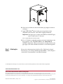
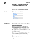
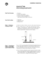
Installation Instructions
PowerFlex® 700L
Drive Cooling Loop Hose Kit
What This Kit Includes
•
•
•
•
Tools That You Need
• Liquid soap
• Tightening wrench
• Backup wrench
Step 1: Attaching a
Coupling to a Hose
A. Lubricate the inside of the hose end with a small amount of liquid soap.
Two hoses
Two drive side couplings
Two heat exchanger side couplings
Two male 1 inch-to-1 inch elbows 37°
(only included with 20L-GHxx-A2 hose kits)
B. Set the coupling down on a solid surface and push the hose onto the
coupling — in one firm push — until the hose end is flush against the
plastic bushing. Stopping before the hose is fully on may make it
difficult to push the hose completely onto the coupling.
Attached
Hose End
Coupling
Step 2: Connecting an
Elbow to a Pipe Nipple
(only 20L-GHxx-A2 Kits)
Solid Surface
To use a 13 kW capacity PowerFlex 700L Liquid-to-Liquid Heat Exchanger
(catalog number 20L-LL13K-P75A) with a PowerFlex 700L Frame 3A
drive, the 20L-GHxx-A2 hose kit comes with 1-inch elbows that must be
exchanged for the elbows provided with the heat exchanger.
A. Use a 1-3/8 inch or adjustable wrench to remove the 1 inch-to-3/4 inch
reducers and 3/4 inch elbows already assembled on the heat exchanger at
the "TO DRIVE INLET" and "FROM DRIVE OUTLET" connections.
(There is no need to use a backup wrnech on the pipe nipple.)
B. Clean off any old thread sealer from inside the pipe nipples on the heat
exchanger.
C. Apply PTFE (Teflon®) thread sealing tape or pipe thread sealant
compound to threads on the 1 inch elbows supplied with the kit.
Important: Only apply tape or sealant to the NPTF end. DO NOT apply
tape or sealant to the 37° flare end.
Teflon is a registered trademark of the DuPont Company.
D. Use a 1-5/16 inch or adjustable wrench to secure the 1 inch elbows to the
heat exchanger at the "TO DRIVE INLET" and "FROM DRIVE
OUTLET" connections. (There is no need to use a backup wrench on the
pipe nipple.) The elbows should be installed in a vertical down pipeline.
Step 3: Attaching the
Hoses
Please refer to the instructions in the PowerFlex 700L Liquid-to-Liquid
Heat Exchanger User Manual (Publication 20L-UM002…) in the Chapter 1
section titled “Connecting Hoses to the Heat Exchanger.”
U.S. Allen-Bradley Drives Technical Support - Tel: (1) 262.512.8176, Fax: (1) 262.512.2222, Email: [email protected], Online: www.ab.com/support/abdrives
www.rockwellautomation.com
Power, Control and Information Solutions Headquarters
Americas: Rockwell Automation, 1201 South Second Street, Milwaukee, WI 53204-2496 USA,Tel: (1) 414.382.2000, Fax: (1) 414.382.4444
Europe/Middle East/Africa: Rockwell Automation, Vorstlaan/Boulevard du Souverain 36, 1170 Brussels, Belgium,Tel: (32) 2 663 0600, Fax: (32) 2 663 0640
Asia Pacific: Rockwell Automation, Level 14, Core F, Cyberport 3, 100 Cyberport Road, Hong Kong,Tel: (852) 2887 4788, Fax: (852) 2508 1846
Publication 20L-IN007A-EN-P – January, 2007
P/N 181738-P01
Copyright © 2007 Rockwell Automation, Inc. All rights reserved. Printed in USA.