1
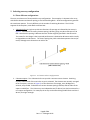
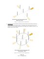
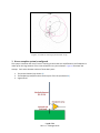
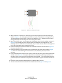
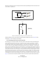
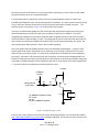
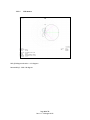
2 Selecting an array configuration
2.1 Three different configurations
The user can select one of three possible array configurations. These employ a 3-element inline array,
with 60-foot element-to-element spacing, as the basic building block. All three configurations generate
the same beam pattern. The only difference is the number of switching directions. The YCCC kit
supports all three options, with details to follow later.
1. 3-element inline: A single array with two directions of coverage as indicated by the arrows in
Figure 1. End-element to center-element spacing is 60 feet, giving an end-to-end span of 120
feet. Note that this spacing is different than the 70 feet originally specified in the NCJ article.
The reason for the change is that improved performance is obtained on 80 meters with virtually
no degradation on 160 meters. The closer spacing also yields a 40m beam pattern that may be
useful, although not as directive as on 160 or 80.
Figure 1. 3-element inline configuration
2. 5-element square: Two 3-element inline arrays with a common center element. Switching
circuitry selects which of the two inline arrays is activated. The elements are normally arranged
to form a square, as shown in Figure 2, so four directions of coverage, every 90 degrees in
azimuth, are provided. End-element to center-element spacing is 60 feet, and the sides of the
square are 84.9 feet. The inline arrays are independent and, if desired, can also be oriented in a
non-square configuration. For example, the arrays can be aimed along the NE-SE axis and the EW axis, forming a rectangle.
Page 5 of 51
Rev. 1.0 – 26 August 2015