1
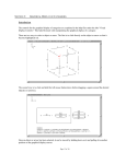
Allen-Bradley GML™ 1394 GMC Turbo SLC™ Interface (Catalog No. GML 3.9.1) Programming Document Update Important User Information Because of the variety of uses for the products described in this publication, those responsible for the application and use of this control equipment must satisfy themselves that all necessary steps have been taken to assure that each application and use meets all performance and safety requirements, including any applicable laws, regulations, codes, and standards. The illustrations, charts, sample programs, and layout examples shown in this guide are intended solely for purposes of example. Since there are many variables and requirements associated with any particular installation, Allen-Bradley does not assume responsibility or liability (to include intellectual property liability) for actual use based upon the examples shown in this publication. Allen-Bradley publication SGI-1.1, Safety Guidelines for the Application, Installation and Maintenance of Solid-State Control (available from your local Allen-Bradley office), describes some important differences between solid-state equipment and electromechanical devices that should be taken into consideration when applying products such as those described in this publication. Reproduction of the contents of this copyrighted publication, in whole or part, without written permission of Allen-Bradley Company, Inc., is prohibited. Throughout this manual we use notes to make you aware of safety considerations: ! ATTENTION: Identifies information about practices or circumstances that can lead to personal injury or death, property damage, or economic loss. Attention statements help you to: • identify a hazard • avoid a hazard • recognize the consequences Important: Identifies information that is critical for successful application and understanding of the product. Note: Identifies additional information that is helpful for successful application and understanding of the product. GML, IMC, SLC, SLC 5/03, SLC 5/04, and SLC 5/05 are trademarks of the Allen-Bradley Company, Inc. Table of Contents Overview . . . . . . . . . . . . . . . . . . . . . . . . . . . . . . . . . . . . . . . . . . . . . . . . . 3 What is the SLC Interface? . . . . . . . . . . . . . . . . . . . . . . . . . . . . . . . . . . . . . 3 Rack Configurations . . . . . . . . . . . . . . . . . . . . . . . . . . . . . . . . . . . . . . . . . . 4 Selecting the SLC Interface in GML . . . . . . . . . . . . . . . . . . . . . . . . . . . . . 5 Selecting the 1394 GMC Turbo in Your SLC Software . . . . . . . . . . . . . . . . 6 Automatically Configuring the 1394 GMC Turbo . . . . . . . . . . . . . . . . . . . . . . 6 Manually Configuring the 1394 GMC Turbo . . . . . . . . . . . . . . . . . . . . . . . . . 7 Manually Configuring Your Third Rack . . . . . . . . . . . . . . . . . . . . . . . . 11 Understanding Discrete Data Transfers . . . . . . . . . . . . . . . . . . . . . . . . . . 14 Transferring Files from the SLC to the 1394 GMC Turbo . . . . . . . . . . . . . . . Transferring Files from the 1394 GMC Turbo to the SLC . . . . . . . . . . . . . . . Dedicated/User-Defined I/O Bits . . . . . . . . . . . . . . . . . . . . . . . . . . . . . . . . 1394 Input Data from the SLC (minimum configuration, one 16-bit word) . . . . . . . . . . . . . . . . . . . . . 1394 Input Data from the SLC (maximum configuration, three 16-bit words) . . . . . . . . . . . . . . . . . . 1394 Output Data from the SLC (minimum configuration, one 16-bit word) . . . . . . . . . . . . . . . . . . . . . 1394 Output Data from the SLC (maximum configuration, three 16-bit words) . . . . . . . . . . . . . . . . . . 14 15 16 17 17 18 18 Defining Your Inputs and Outputs . . . . . . . . . . . . . . . . . . . . . . . . . . . . . . 19 Defining the I/O Configuration . . . . . . . . . . . . . . . . . . . . . . . . . . . . . . . . . . Defining Input Bits . . . . . . . . . . . . . . . . . . . . . . . . . . . . . . . . . . . . . . . . . . . Defining Input Floats . . . . . . . . . . . . . . . . . . . . . . . . . . . . . . . . . . . . . . . . . Defining Output Bits . . . . . . . . . . . . . . . . . . . . . . . . . . . . . . . . . . . . . . . . . Defining Output Floats . . . . . . . . . . . . . . . . . . . . . . . . . . . . . . . . . . . . . . . . 19 21 22 23 25 Understanding M Files . . . . . . . . . . . . . . . . . . . . . . . . . . . . . . . . . . . . . . 26 Types of M Files . . . . . . . . . . . . . . . . . . . . . . . . . . . . . . . . . . . . . . . . . . . . Transfer Modes . . . . . . . . . . . . . . . . . . . . . . . . . . . . . . . . . . . . . . . . . . . . . Automatic Mode . . . . . . . . . . . . . . . . . . . . . . . . . . . . . . . . . . . . . . . . . . . . Handshaking Mode . . . . . . . . . . . . . . . . . . . . . . . . . . . . . . . . . . . . . . . . . . Updating M0 files using Handshaking Mode . . . . . . . . . . . . . . . . . . . . . . . Updating M1 files using Handshaking Mode . . . . . . . . . . . . . . . . . . . . . . . Enabling M File Transfers . . . . . . . . . . . . . . . . . . . . . . . . . . . . . . . . . . . . . Defining M0 Floats . . . . . . . . . . . . . . . . . . . . . . . . . . . . . . . . . . . . . . . . . . Defining M0 Integers . . . . . . . . . . . . . . . . . . . . . . . . . . . . . . . . . . . . . . . . . Defining M1 Floats . . . . . . . . . . . . . . . . . . . . . . . . . . . . . . . . . . . . . . . . . . Defining M1 Integers . . . . . . . . . . . . . . . . . . . . . . . . . . . . . . . . . . . . . . . . . 27 27 27 27 28 29 31 32 33 34 35 Fault Handling . . . . . . . . . . . . . . . . . . . . . . . . . . . . . . . . . . . . . . . . . . . . 36 Interrupts . . . . . . . . . . . . . . . . . . . . . . . . . . . . . . . . . . . . . . . . . . . . . . . . 36 Programmable Limit Switch Example . . . . . . . . . . . . . . . . . . . . . . . . . . . 36 GML Program . . . . . . . . . . . . . . . . . . . . . . . . . . . . . . . . . . . . . . . . . . . . . . 36 SLC Program . . . . . . . . . . . . . . . . . . . . . . . . . . . . . . . . . . . . . . . . . . . . . . . 37 Publication 999-104-DU1.1 — February 1999 ii Table of Contents Publication 999-104-DU1.1 — February 1999 1394 GMC Turbo SLC Interface 1 Introduction The following information reflects changes for GML™ version 3.9.1. Use this Document Update in conjunction with the GML 3.8 User Manual (Publication 999-104) August 1, 1995 and the GML Version 3.9.0 Document Update (Publication 999-104-DU1— January 1997). This document supersedes the GML 1394 GMC Turbo SLC™ Interface Programming Document Update (Publication 999-104-DU1.1— February 1997). 1394 GMC Turbo SLC Interface Hardware Overview This section provides information required to enable and set up the 1394 GMC Turbo SLC Interface. The information in this document assumes you have a basic understanding of SLC programming and the 1394 GMC system. What is the SLC Interface? The 1394 GMC Turbo allows you to connect an SLC rack, containing an SLC 5/ 03™, SLC 5/04™, or SLC 5/05™ processor to the 1394 GMC Turbo using a 1746-C7 (flat 6 in.) or 1746-C9 (round 36 in.) SLC local rack extension cable. This connection provides direct backplane communications between the SLC and the 1394 as shown in figure 1. Important: The SLC 5/03 must be running firmware version OS301 or later. Important: If the SLC interface is enabled, the RIO adapter on the 1394 Turbo is not operational. The interface supports discrete input and output files up to 32 words in length, M0 and M1 files up to 512 words in length, and an ISR interrupt. Figure 1 Connecting an SLC to a 1394 GMC Turbo SLC right side connector SLC IN connector SLC OUT connector 1746 Rack with SLC 5/03, 5/04 or 5/05 174 6-C 7 or -C9 cab le 1394-SJTxx-T Publication 999-104-DU1.1 — February 1999 2 1394 GMC Turbo SLC Interface Rack Configurations The SLC views the 1394 Turbo as a four-slot rack with one intelligent module installed in the first slot. The remaining empty slots are reserved by the 1394 GMC Turbo and cannot be used. SLC racks are available with 4, 7, 10, and 13 slots. Because the SLC can address a maximum of 30 slots and support up to three racks, the largest logic configuration containing two 1394 GMC Turbos is one 13-slot rack in which the first 1394 GMC Turbo appears in slot 13 and the second 1394 GMC Turbo appears in slot 17, as shown in Figure 2. Slots 14, 15, 16, 18, 19 and 20 are reserved. The largest logic configuration containing one 1394 GMC Turbo is two 13-slot racks, as shown in Figure 3. In Figure 3, the 1394 GMC Turbo appears in slot 26. Slots 27, 28 and 29 are reserved. Figure 2 Largest Configuration Containing Two 1394 GMC Turbo Modules 1746 Rack with SLC 5/03, 5/04, or 5/05 1394-SJTxx-T (slots 13-16) 13-slot SLC Rack (0-12) First 1394 appears as a 4-slot Rack with a module located in slot 13 1394-SJTxx-T (slots 17-20) Status Status Second 1394 appears as a 4-slot Rack with a module located in slot 17 Figure 3 Largest Configuration Containing One 1394 GMC Turbo Module 13-slot SLC Rack (0-12) 1746 Rack with SLC 5/03, 5/04, or 5/05 13-slot SLC Rack (13-25) 1746 I/O Expansion Rack 1394-SJTxx-T (slots 26-29) Status 1394 appears as a 4-slot Rack with a module located in slot 26 Publication 999-104-DU1.1 — February 1999 1394 GMC Turbo SLC Interface Selecting the SLC Interface in GML 3 To select the SLC interface in GML 3.9.1: 1. From the menu bar, select Definitions. The Definitions menu appears. 2. Select Control Options. The IMC S/200 Options window appears. 3. Select the number of axes you want to use in the Control type area. 4. Select 1394 Integrated Drive. 5. Select SLC Interface. Note: If you select the SLC Interface, you cannot select the RIO Interface. 6. Select Save. The IMC S/200 Options window disappears. 7. Insert the serial cable from your PC into serial port A of your 1394 GMC Turbo Module. 8. Select Diagram. The Diagram menu appears. 9. Select Online. The Online Manager for New Diagram window appears. 10. Select Download Diagram. The Download Diagram window disappears. 11. When the diagram has successfully downloaded, press Reset on the 1394 GMC Turbo Module. The SLC Interface in the GMC Turbo Module is activated for communication with the SLC backplane. Publication 999-104-DU1.1 — February 1999 4 1394 GMC Turbo SLC Interface Selecting the 1394 GMC Turbo in Your SLC Software After you select the SLC Interface in GML 3.9.1, you need to configure the SLC to communicate with the 1394 GMC Turbo Module. Use the table below to determine which configuration procedure to follow. When Working: Go to: On-line Automatically Configuring the 1394 GMC Turbo Off-line Manually Configuring the 1394 GMC Turbo Automatically Configuring the 1394 GMC Turbo To configure your 1394 GMC Turbo system automatically: 1. From the menu bar, select File. The File menu appears. 2. Select New. The Select Processor Type window appears. 3. Assign a name for your new RSLogix 500 project file and type it in the Processor Name field. 4. Select your SLC processor from the list of processor types. Default values assigned to the selected processor appear in the Communications Setting area. 5. Select OK. The processor database is initialized and the RSLogix 500 navigator window appears with the name you typed in the Processor Name field. 6. In the navigator window, double-click on I/O Configuration. The I/O Configuration window appears. Publication 999-104-DU1.1 — February 1999 1394 GMC Turbo SLC Interface 5 7. To automatically configure your 1394 GMC Turbo Module, select Read I/O Config. The Read I/O Configuration From Online Processor window appears showing the parameters of the read process. 8. Select Read I/O Config. The SLC processor reads the configuration of your first rack (containing the SLC processor), second rack, and the optional third rack. Manually Configuring the 1394 GMC Turbo To configure your 1394 GMC Turbo system in manual mode: 1. From the menu bar, select File. The File menu appears. 2. Select New. The Select Processor Type window appears. 3. Assign a name for your new RSLogix 500 project file and type it in the Processor Name field. 4. Select your SLC processor from the list of processor types. Default values assigned to the selected processor appear in the Communications Setting area. 5. Select OK. The processor database is initialized and the RSLogix 500 navigator window appears with the name you typed in the Processor Name field. Publication 999-104-DU1.1 — February 1999 6 1394 GMC Turbo SLC Interface 6. In the navigator window, double-click on I/O Configuration. The I/O Configuration window appears. In the example below, field 1 in the Racks area contains a four slot rack. 7. Your hardware configuration determines the number of slots in the first rack. If your first rack has: In field 1 of the Racks area, select: These slots appear below the Racks area in the # column: 4 slots 1746-A4 4-Slot Rack 0-3 7 slots 1746-A7 7-Slot Rack 0-6 10 slots 1746-A10 10-Slot Rack 0-9 13 slots 1746-A13 13-Slot Rack 0-12 Note: Your SLC processor always appears in slot 0. The remaining slots are available for assigning to other hardware. 8. Your hardware configuration determines the number of slots in the second rack. If your second rack has: In field 2 of the Racks area, select: Publication 999-104-DU1.1 — February 1999 4 slots 1746-A4 4-Slot Rack 7 slots 1746-A7 7-Slot Rack 10 slots 1746-A10 10-Slot Rack 13 slots 1746-A13 13-Slot Rack 0 slots (not present) I/O Rack Not Installed 1394 GMC Turbo SLC Interface Note: The table below is provided as a guide. The sequencing of your second rack slots depend on the number of slots in each rack. If your second rack has: 4 slots 7 slots 10 slots 13 slots Note: 7 And your first rack has: Then your second rack slots are: 4 slots 4-7 7 slots 7-10 10 slots 10-13 13 slots 13-16 4 slots 4-10 7 slots 7-13 10 slots 10-16 13 slots 13-19 4 slots 4-13 7 slots 7-16 10 slots 10-19 13 slots 13-22 4 slots 4-16 7 slots 7-19 10 slots 10-22 13 slots 13-25 In the example below, field 1 and 2 each contain a four slot rack. The first rack slots are numbered 0-3 and the second rack slots are numbered 4-7. Publication 999-104-DU1.1 — February 1999 8 1394 GMC Turbo SLC Interface 9. If your second rack is a: Then: 1394 and there is no third rack Go to step 10. 1394 and there is a third rack Go to Manually Configuring Your Third Rack. SLC Go to Manually Configuring Your Third Rack. 10. Select the first of your second rack slots. The row containing slot (4, 7, 10, or 13) is highlighted. In the example below, slot four is selected. 11. In the Filter field of the Current Cards Available area, select Interface. Part numbers and descriptions appear in the Current Cards Available area. 12. Select 1394-SJT GMC Turbo System. Note: An alternative way to assign the GMC Turbo Module is to double-click on Other in the list, type 13617 in the Other Type I/O Card window, and select OK. 13. Press Enter. The part number and description of the GMC Turbo Module appears in the slot you selected. Publication 999-104-DU1.1 — February 1999 1394 GMC Turbo SLC Interface 9 14. Select Adv Config. The Advanced I/O Configuration window appears showing the slot you selected and default information for the 1394-SJT GMC Turbo Module. 15. Select OK. Manually Configuring Your Third Rack To configure your third rack in manual mode: 1. If your GMC Turbo System has: Then: Two racks 1. In field 3 of the Racks area, select I/O Rack Not Installed. Your configuration is complete. 2. Go to Understanding Discrete Data Transfers. Three racks Go to step 2. 2. In field 3 of the Racks area, select 1746-A4 4-Slot Rack. Note: The table below is provided as a guide. The sequencing of your third rack slots depend on the number of slots in the second rack. If the last slot from rack two is: Then the third rack slots are: 7 8-11 10 11-14 13 14-17 16 17-20 19 20-23 22 23-25 25 26-29 Publication 999-104-DU1.1 — February 1999 10 1394 GMC Turbo SLC Interface Note: In the example below, field 3 contains a four slot rack that is numbered 8-11. 3. If your GMC Turbo System includes: Then: One 1394 and it’s in rack 3 Go to step 4. Two 1394s and you selected the 1394 SJT-GMC Turbo module in rack 2 Go to Understanding Discrete Data Transfers 4. Select the first of your third rack slots. The row containing slot (8, 11, 14, 17, 20, 23, or 26) is highlighted. In the example below, slot 8 is selected. 5. In the Filter field of the Current Cards Available area, select Interface. Part numbers and descriptions appear in the Current Cards Available area. 6. Select 1394-SJT GMC Turbo System. Note: Publication 999-104-DU1.1 — February 1999 An alternative way to assign the GMC Turbo Module is to double-click on Other in the listing, type 13617 in the Other Type I/O Card window, and select OK. 1394 GMC Turbo SLC Interface 11 7. Press Enter. The part number and description of the GMC Turbo Module appears in the slot you selected. 8. Select Adv Config. The Advanced I/O Configuration window appears showing the slot number you selected and default information for the 1394SJT GMC Turbo Module. 9. Select OK. Publication 999-104-DU1.1 — February 1999 12 1394 GMC Turbo SLC Interface Understanding Discrete Data Transfers The 1394 GMC Turbo and the SLC use input and output files to transfer discrete data. Each input and output file can support up to 32 words (0-31). Those 32 words include: • Eight dedicated bits and eight user bits (located in word 0). • Up to 32 additional user bits (located in words 1 and 2). • Up to 15 floating-point variables (located in words 3-31). Transferring Files from the SLC to the 1394 GMC Turbo To transfer discrete files from the SLC to the 1394: 1. Determine the slot number of the 1394. In the figure below, the 1394 GMC Turbo appears in slot four. Figure 4 Typical SLC to 1394 GMC Turbo Configuration Four-slot SLC Rack with a 5/03 processor (0-3) 1394-SJT-T is located in slot four (4-7) Status 2. Determine the number of elements to send (8-39 user-defined bits, 0-15 floating-point variables). Figure 5 shows eight user-defined bits and two floating-point variables being transferred from the SLC to the 1394. 3. Optimize scan time by defining the discrete file size. 4. Define the eight user bits. One of the user bits (O:4.0/8) is named start (bit 0) in GML. 5. Define the two floating-point variables. 6. Link those floating-point variables to GML user variables. The floating-point variables are linked to the GML user variables user variable 1 and user variable 2. When the SLC finishes its program scan, it updates its outputs. In order for the GML program to recognize this new data, the 1394 GMC Turbo must update its inputs. The SLC update rate depends on the size of the user's program. The update rate for the 1394 GMC Turbo depends on the I/O file update rate (slow, medium or fast) and the servo update rate that you selected. Refer to the remainder of this document and the SLC 500 Reference Manual (Publication 1747-6.15) for specific programming instructions. Publication 999-104-DU1.1 — February 1999 1394 GMC Turbo SLC Interface 13 Figure 5 Transferring Files from the SLC to the 1394 GMC Turbo 1394 Input File SLC Output File User Bit 0 (named Start) Bit Location O:4.0/8 Word 0 Dedicated Bits (0-7) Word 0 Dedicated Bits (0-7) 8 User Bits (8-15) 8 User Bits (8-15) 1 1 Input_Float_user variable_1 Floating-Point 1 (32 bit) 2 2 3 3 Input_Float_user variable_2 Floating-Point 2 (32 bit) 4 4 Transferring Files from the 1394 GMC Turbo to the SLC To transfer discrete files from the 1394 to the SLC: 1. Determine where the Turbo Module resides. In the figure below, the 1394SJT GMC Turbo Module resides in slot four. Figure 6 Typical 1394 GMC Turbo to SLC Configuration Four-slot SLC Rack with a 5/03 processor (0-3) 1394-SJT-T is located in slot four (4-7) Status 2. Determine the number of elements to send (8-39 user-defined bits, 0-15 floating-point variables). Figure 7 shows 24 user-defined bits and two floating-point variables being transferred from the 1394 to the SLC. 3. Optimize scan time by defining the discrete file size. 4. Define the eight user bits. One of the user bits (I:4.0/8) is defined as stop (bit 0) in GML and is sent to the SLC to let the SLC know the program has stopped. Publication 999-104-DU1.1 — February 1999 1394 GMC Turbo SLC Interface 14 5. Define the two floating-point variables. The floating-point variables are linked to the GML user variables user variable 1 and user variable 2. The rate at which the GML program updates its outputs depends on the I/O file update rate (slow, medium, or fast) and the servo update rate that you selected. In order for the SLC to access this new data, the inputs require updating. The SLC accesses this new data during the next input scan. The rate at which the SLC program updates its inputs depends on the size of your program. Refer to the remainder of this document and the SLC 500 Reference Manual (Publication 1747-6.15) for specific programming instructions. Figure 7 Transferring a File from the 1394 GMC Turbo to the SLC SLC Input File 1394 Output File Bit Location I:4.0/8 Word 0 Dedicated Bits (0-7) 1 8 User Bits (8-15) User Bits (16-31) 1 Dedicated Bits (0-7) 8 User Bits (8-15) User Bits (16-31) 2 2 3 User Bit 0 (named Stop) Word 0 Floating-Point 1 (32 bit) 3 Output_Float_Actual_Position_Axis0 4 4 Floating-Point 2 (32 bit) 5 Output_Float_Actual_Position_Axis0 5 Dedicated/User-Defined I/O Bits The first word in each I/O file contains dedicated Control/Status bits (Bits 0-7) and user-defined I/O bits (Bits 8-15). The minimum SLC I/O file configuration consists of one 16-bit word. The maximum I/O file configuration consists of three 16-bit words. Refer to the following tables for examples of the minimum and maximum input configurations and definitions of the dedicated Control/Status bits. Publication 999-104-DU1.1 — February 1999 1394 GMC Turbo SLC Interface 15 1394 Input Data from the SLC (minimum configuration, one 16-bit word) Word Bit Description Definition 0 0/0 Run program When this bit changes from 0 to 1, the GML application program executes from the beginning. If the application program is already running or paused, the change has no effect. The SLC stop bit described below has priority over this bit. This bit cannot be accessed by the GML program. 0/1 Stop program When this bit is set to 1, the application program stops. This bit cannot be accessed by the GML program. This bit has priority over the Run and Pause bits. 0/2 Pause/resume program When this bit changes from 0 to 1, the GML application program pauses. When the bit changes from 1 to 0, the program resumes. This bit cannot be accessed by the GML program. 0/3 SLC process fault When the SLC sets this bit to 1, the 1394 GMC Turbo system software generates a global fault. The corresponding global fault code indicates the SLC process fault. This bit cannot be accessed by the GML program. 0/4 Reserved N/A 0/5 Reserved N/A 0/6 M0 file update request If M file handshaking is enabled, the SLC ladder program can set this bit to 1, which causes the 1394 GMC Turbo to update the M0 file. The GML program references this bit as the system variable SLC_M0_Update_Request. 0/7 M1 file update acknowledge If M file handshaking is enabled, the SLC ladder program can set this bit to 1, which causes the SLC ladder program to acknowledge the 1394's request to update the M1 file. The GML program references this bit as the system variable SLC_M1_Update_Acknowledge. 0/8-0/15 User defined N/A 1394 Input Data from the SLC (maximum configuration, three 16-bit words) Word Bit Description Definition 0 0/0 Run program When this bit changes from 0 to 1, the GML application program executes from the beginning. If the application program is already running or paused, the change has no effect. The SLC stop bit described below has priority over this bit. This bit cannot be accessed by the GML program. 0/1 Stop program When this bit is set to 1, the application program stops. This bit cannot be accessed by the GML program. This bit has priority over the Run and Pause bits. 0/2 Pause/resume program When this bit changes from 0 to 1, the GML application program pauses. When the bit changes from 1 to 0, the program resumes. This bit cannot be accessed by the GML program. 0/3 SLC process fault When the SLC sets this bit to 1, the 1394 GMC Turbo system software generates a global fault. The corresponding global fault code indicates the SLC process fault. This bit cannot be accessed by the GML program. 0/4 Reserved N/A 0/5 Reserved N/A 0/6 M0 file update request If M file handshaking is enabled, the SLC ladder program can set this bit to 1, which causes the 1394 GMC Turbo to update the M0 file. The GML program references this bit as the system variable SLC_M0_Update_Request. 0/7 M1 file update acknowledge If M file handshaking is enabled, the SLC ladder program can set this bit to 1, which causes the SLC ladder program to acknowledge the 1394's request to update the M1 file The GML program references this bit as the system variable SLC_M1_Update_Acknowledge. 0/8-0/15 User defined N/A 1 1/0-1/15 User defined N/A 2 2/0-2/15 User defined N/A Publication 999-104-DU1.1 — February 1999 1394 GMC Turbo SLC Interface 16 1394 Output Data from the SLC (minimum configuration, one 16-bit word) Word Bit Description Definition 0 0/0 Program running This bit is set to 1 by the 1394 GMC Turbo while the GML application program is running. This bit cannot be accessed directly by the GML program. 0/1 Global fault This bit is set to 1 by the 1394 GMC Turbo if a fault has occurred. This bit cannot be accessed directly by the GML program. 0/2 Reserved N/A 0/3 Reserved N/A 0/4 Reserved N/A 0/5 M file handshake enabled When set to 1, this bit indicates that M files will be updated using handshaking mode. When set to 0, this bit indicates that M files will be updated using automatic mode. 0/6 M0 file update acknowledge This bit is set to 1 by the GML program to indicate that an M0 file update has been acknowledged and in process. Bit 6 can be written by the GML program. This bit is referenced by the GML program as the system variable SLC_M0_Update_Acknowledge. 0/7 M1 file update request This bit is set to 1 by the GML program to request an M1 file update. The 1394 GMC Turbo system software resets this bit to 0 when the update is complete. Bit 7 can be written by the GML program. This bit is referenced by the GML program as the system variable SLC_M1_Update_Request. 0/8-0/15 User defined N/A 1394 Output Data from the SLC (maximum configuration, three 16-bit words) Word Bit Description Definition 0 0/0 Program running This bit is set to 1 by the 1394 GMC Turbo while the GML application program is running. This bit cannot be accessed directly by the GML program. 0/1 Global fault This bit is set to 1 by the 1394 GMC Turbo if a fault has occurred. This bit cannot be accessed directly by the GML program. 0/2 Reserved N/A 0/3 Reserved N/A 0/4 Reserved N/A 0/5 M file handshake enabled When set to 1, this bit indicates that M files will be updated using handshaking mode. When set to 0, this bit indicates that M files will be updated using automatic mode. 0/6 M0 file update acknowledge This bit is set to 1 by the GML program to indicate that an M0 file update has been acknowledged and in process. Bit 6 can be written by the GML program. The GML program refers to this bit as the system variable SLC_M0_Update_Acknowledge. 0/7 M1 file update request This bit is set to 1 by the GML program to request an M1 file update. The 1394 GMC Turbo system software resets this bit to 0 when the update is complete. Bit 7 can be written by the GML program. The GML program refers to this bit as the system variable SLC_M1_Update_Request. 0/8-0/15 User defined N/A 1 1/0-1/15 User defined N/A 2 2/0-2/15 User defined N/A Publication 999-104-DU1.1 — February 1999 1394 GMC Turbo SLC Interface Defining Your Inputs and Outputs 17 Once you have selected the SLC Interface, you need to define the following: • I/O configuration • Input bits • Input floats (floating-point variables) • Output bits • Output floats (floating-point variables) Defining the I/O Configuration To define the I/O Configuration: 1. From the main menu, select Definitions. The Definitions menu appears. 2. Select SLC Interface. The SLC Interface menu appears. Publication 999-104-DU1.1 — February 1999 18 1394 GMC Turbo SLC Interface 3. Select I/O Configuration. The SLC I/O Configuration window appears. 4. Make entries in the following fields: Field: Description: I/O File Update Rate I/O image file updates to and from the SLC are executed from the servo interrupt routine, and are independent of the SLC I/O scan. The higher the setting, the more CPU utilization is impacted. Definitions of I/O update rates are: Slow The complete I/O image file is updated every four servo loops. Medium The complete I/O image is updated every two servo loops. Fast The complete I/O image file is updated every servo interrupt. General-Purpose Select the number of input bits you need. Inputs (Bits)1 General-Purpose Select the number of input floats you need. Inputs (Floats)1 General-Purpose Select the number of output bits you need. Outputs (Bits)1 General-Purpose Select the number of output floats you need. Outputs (Floats)1 1 Publication 999-104-DU1.1 — February 1999 There are 32 words of I/O available in each SLC I/O file. Each float consists of two 16 bit words. I/O floating-point addressing starts at the word following the last discrete I/O. 1394 GMC Turbo SLC Interface 19 Note: If you: You can define: Select eight or 24 discrete I/O points Up to 15 floats. Configure all 40 I/O points Up to 14 floats. 5. Select Save. The I/O Configuration window disappears. 6. Go to Defining Input Bits. Defining Input Bits After you have selected the number of input bits required for your application, you need to define those bits. To define your input bits: 1. From the main menu bar, select Definitions. The Definitions menu appears. 2. Select SLC Interface. The SLC Interface menu appears. 3. Select Input Bits. The SLC Input Bits window appears. 4. Select New. The SLC Input Bit window appears. Publication 999-104-DU1.1 — February 1999 20 1394 GMC Turbo SLC Interface 5. Make entries in the following fields: Field: Description: Name Type the name of the bit. SLC User Input Bit Type the number of the bit (0-39). 6. Select Save. The SLC Input Bit Definition window disappears. 7. If you: Then: Need to define more input bits Go to step 4. Do not need to define more input bits Go to step 8. 8. Select Done. The SLC Input Bits window disappears. Note: If a GML error window appears, you may have named more input bits than you selected in the I/O Configuration window. Check the I/O Configuration window to verify that you have selected the correct number of General-Purpose Inputs (Bits) for your application. 9. Go to Defining Input Floats. Defining Input Floats After you have selected the number of input floats required for your application, you can link those input floats to user variables. To link the input floats: 1. From the menu bar, select Definitions. The Definitions menu appears. 2. Select SLC Interface. The SLC interface menu appears. 3. Select Input Floats. The SLC Input Floats window appears. Publication 999-104-DU1.1 — February 1999 1394 GMC Turbo SLC Interface 21 4. Select New. The Input_Float_ window appears. 5. Select the user variable you want to link. 6. Select Save. The Input_Float_ window disappears. 7. If you: Then: Need to link more input floats Go to step 4. Do not need to link more input floats Go to step 8. 8. Select Done. The SLC Input Floats window disappears. 9. Go to Defining Output Bits. Note: If you delete a linked user variable or system variable, you must either create another linked variable to that same SLC Input Float or delete the SLC Input Float entirely. Defining Output Bits After you have selected the number of output bits required for your application, you need to define those bits. To define your output bits: 1. From the menu bar, select Definitions. The Definitions menu appears. 2. Select SLC Interface. The SLC interface menu appears. Publication 999-104-DU1.1 — February 1999 22 1394 GMC Turbo SLC Interface 3. Select Output Bits. The SLC Output Bits window appears. 4. Select New. The SLC Output Bit window appears. 5. Make entries in the following fields: Field: Description: Name Type the name of the bit. SLC User Output Bit Type the number of the bit (0-39). 6. Select Save. The SLC Output Bit Definition window disappears. 7. If you: Then: Need to define more output bits Go to step 4. Do not need to define more output bits Go to step 8. 8. Select Done. The SLC Output Bits window disappears. Note: If a GML error window appears, you may have named more output bits than you selected in the I/O Configuration window. Check the I/O Configuration window to verify that you have selected the correct number of General-Purpose Outputs (Bits) for your application. 9. Go to Defining Output Floats. Publication 999-104-DU1.1 — February 1999 1394 GMC Turbo SLC Interface 23 Defining Output Floats Output floats can pass either user variables or a select list of system variables. After you have selected the number of output floats, you need to link those output floats to user or system variables. To link the output floats: 1. From the menu bar, select Definitions. The Definitions menu appears. 2. Select SLC Interface. The SLC Interface menu appears. 3. Select Output Floats. The SLC Output Floats window appears. 4. Select New. The Output_Float_ window appears. 5. Select the type of variable (user or system) you want to link to your output float. Note: If you selected System Variables, you need to select the axis you want the output float linked to. Publication 999-104-DU1.1 — February 1999 24 1394 GMC Turbo SLC Interface 6. Select the variable you want to link to the output float from the list in the Linked Variable field. 7. Select Save. The Output_Float_ window disappears. 8. If you: Then: Need to link more output floats Go to step 5. Do not need to link more output floats Go to step 9. 9. Select Done. The SLC Output Floats window disappears. Note: Understanding M Files If you delete a linked user variable or system variable, you must either create another linked variable to that same SLC Output Float or delete the SLC Output Float entirely. M files are used to transfer large, non-time-critical groups of data, such as endpoints and CAM tables, between the 1394 GMC Turbo and the SLC. M files are updated when ever they are accessed during read/write functions. Each M file is 1024 bytes and can contain all integers, all floating-points, or a combination of both. If an M File contains all: The maximum number of elements is: Integer elements 512 (each integer element is 16 bits (one word)). Floating-point elements 256 (each floating-point element is 32 bits (two words)). Important: If an M file contains both integers and floating-points, the floatingpoint elements are located in front of the integer elements. Use the formula below to determine the proportions of your combination: (number of floating-points x 2) + (number of integers) < _ 512 For example, if your M file contains 100 floating-point elements, the maximum number of integer elements available is 312. M files can be accessed using indirect variables. This allows elements in the M file to be indexed like an array. M file variables do not need assigned names to be referenced indirectly. Publication 999-104-DU1.1 — February 1999 1394 GMC Turbo SLC Interface 25 Types of M Files There are two types of M Files: • M0 files are used to transfer data from the SLC to the 1394 GMC Turbo. • M1 files are used to transfer data from the 1394 GMC Turbo to the SLC. Transfer Modes GML supports two different M file update modes. • Automatic mode • Handshaking mode Automatic Mode When automatic mode is enabled, the SLC notifies the 1394 GMC Turbo every time it writes new data to the M0 file. The 1394 GMC Turbo does not know which portion of the M0 file has been updated and therefore copies the entire file each time, even if only one element was written. Depending on your application and the size of your M files, these numerous updates can impact your CPU utilization. Automatic mode is ideal for applications with small M files that contain elements that do not have to be updated at the same time. Automatic mode still requires that you handshake M1 files. Handshaking Mode When handshaking mode is enabled, the 1394 GMC Turbo ignores the automatic SLC update notifications and waits for the program to set a system bit. This decreases the number of updates and therefore minimizes the impact on your CPU utilization. Handshaking mode is ideal for applications with large M files that contains elements that need to be updated at the same time. For example, if your application requires position, velocity and acceleration data to make a move, and those elements are located in a file with 100 other elements, you have to update all of the elements at the same time to make sure that the data you need is current. Using automatic mode, you cannot verify that the three elements you need were updated at the same time because they may have been updated at different points during the program. Using handshaking mode, you can update all of the elements you need and then transfer them all at the same time instead of updating each element one at a time. Publication 999-104-DU1.1 — February 1999 26 1394 GMC Turbo SLC Interface Updating M0 files using Handshaking Mode When M0 files are updated using handshaking mode: • The SLC program updates the M0 file variables and issues the M0 Update Request bit (bit 6). • The GML program sees the system bit variable SLC_M0_Update_Request (bit 6) and sets the system bit variable SLC_M0_Update_Acknowledge. • The 1394 GMC Turbo system firmware waits for the GML program to set this bit and then starts the update. • The SLC program waits for the M0 Update Acknowledge bit to be set and then resets the M0 Update Request bit to 0. This serves as a signal to the 1394 GMC Turbo system that the SLC has recognized the start of the update. • After the 1394 GMC Turbo completes the update, and the M0 Update Request bit has been reset, the 1394 system firmware resets the system bit variable SLC_M0_Update_Acknowledge. • The GML program waits for the M0_Update_Acknowledge bit to reset and the update is complete. Figure 8 Typical Ladder Logic Diagram for M0 File Transfers Rung 2:0 | True only Remove M0 | | for first update | | pass request | | S:1 O:4 | [----------------------------------------------------------------------------+----(U)-----+-| |----] [----------------------------------------------------------------------------+----(U)----+-| | 15 | 6 | | | Clear M1 | | | | update ack | | | | | | | | | O:4 | | +----(U)-----+ | | 7 | | Rung 2:1 | No M0 |No M0 Copy data | | update in |update to m0 file | | process |requested (50 float loat | values) | | | I:4 O:4 +COP---------------+ | +COP---------------+ |----]/[--------]/[-------------------------------------------------------+-+COPY PY FILE +-+-| |----]/[--------]/[-------------------------------------------------------+-+CO |Source | 6 6 | |Source #F8:20| | | | | |Dest #M0:4.0| | | |Dest | | |Length 100| | | |Length | | +------------------+ +------------------+ | | | | Request | | Request M0 update | | update | | | | O:4 | | | +----(L)---------------+ +----(L)---------------+ | 6 | | Rung 2:2 | M0 update |M0 update | Remove M0 | | requested |in process| update | | | request | | O:4 I:4 O:4 | [------------------------------------------------------------------------(U)-----| |----] [--------] [------------------------------------------------------------------------(U)-----| | 6 6 6 | Publication 999-104-DU1.1 — February 1999 1394 GMC Turbo SLC Interface 27 Figure 9 Typical GML Program for M0 File Transfers Handshake M0 File Handshake M0 File Updating M1 files using Handshaking Mode When M1 files are updated using handshaking mode: • The GML program updates the M1 variables and then issues the system bit variable SLC_M1_Update_Request. • Once the SLC program sees the request, it issues the M1 Update Acknowledge when ready bit. • Once both bits are issued, the 1394 GMC Turbo system software begins the update. • When the update is completed, the 1394 GMC Turbo resets the SLC_M1_Update_Request. • The SLC waits for the M1 Update Request bit to reset and then clears the M1 Update Acknowledge bit. The update is completed and the SLC can copy the new data from the M1 file. Publication 999-104-DU1.1 — February 1999 28 1394 GMC Turbo SLC Interface Figure 10 Typical Ladder Logic Diagram for M1 File Transfers Rung 2:0 | True only Remove M0 | | for first update | | pass request | | S:1 O:4 | |----] [----------------------------------------------------------------------------+----(U)----+-| [----------------------------------------------------------------------------+----(U)-----+-| | 15 | 6 | | | Clear M1 | | | | | update ack | | | | | | | O:4 | | | +----(U)-----+ | | 7 | | Rung 2:3 | M1 update |M1 update | Assert M1 | | request |ack not | update ack | | |set | | | I:4 O:4 O:4 | |----] [--------]/[------------------------------------------------------------------------(L)-----| [--------]/[------------------------------------------------------------------------(L)-----| | 7 7 7 | Rung 2:4 | M1 update |M1 update Copy data | | ack set |complete from M1 | (50 float | | values) | | +COP---------------+ | O:4 I:4 +COP---------------+ | |----] [--------]/[-------------------------------------------------------+-+COPY +-+-| [--------]/[-------------------------------------------------------+-+COPY FILE | 7 7 | |Source #M1:4.0| | | |Source |Dest st #F8:20| | | | | |De |Length | | |Length 50| | | | | +------------------+ +------------------+ | | | | | | | | Clear | | Cle r M1 | | update | | update ack | | | | | | O:4 | | | +----(U)---------------+ +----(U)---------------+ | 7 | | Figure 11 Typical GML Program for M1 File Transfers Handshake M1 File Handshake M1 File Publication 999-104-DU1.1 — February 1999 1394 GMC Turbo SLC Interface 29 Enabling M File Transfers To enable M file transfers in GML: 1. From the menu bar, select Definitions. The Definitions menu appears. 2. Select SLC Interface. The SLC Interface menu appears. 3. Select SLC M File Configuration. The SLC M File Configuration window appears. 4. Make entries in the following fields: Field: Description: Transfers Select ON. Transfer Mode Select a mode. Refer to the Transfer mode section for more information. Number of Floats (M0 file) Type the number of floats you need in the M0 file. Number of Integers Type the number of integers you need in the M0 file. (M0 file) Number of Floats (M1 file) Type the number of floats you need in the M1 file. Number of Integers Type the number of integers you need in the M1 file. (M1 file) Note: The number of M0 and M1 words specified above should match the number of words set in the SPIO section of your SLC 500 program software. 5. Select Save. The SLC M File Configuration window disappears. 6. Go to Defining M0 Floats. Publication 999-104-DU1.1 — February 1999 30 1394 GMC Turbo SLC Interface Defining M0 Floats To define the M0 floats: 1. From the menu bar, select Definitions. The Definitions menu appears. 2. Select SLC Interface. The SLC Interface menu appears. 3. Select M0 Floats. The Defined M0 Floats window appears. 4. Select New. The M0 Float window appears. 5. Make entries in the following fields: Field: Description: Name Type the name of the float. Initialize Type the number of the float. 6. Select Save. The M0 Float window disappears. 7. If you: Then: Need to link more M0 floats Go to step 5. Do not need to link more M0 floats Go to step 8. 8. Select Done. The Defined M0 Floats window disappears. 9. Go to Defining M0 Integers. Publication 999-104-DU1.1 — February 1999 1394 GMC Turbo SLC Interface 31 Defining M0 Integers To define the M0 integers: 1. From the menu bar, select Definitions. The Definitions menu appears. 2. Select SLC Interface. The SLC Interface menu appears. 3. Select M0 Integers. The Defined M0 Integers window appears. 4. Select New. The M0 Integer window appears. 5. Make entries in the following fields: Field: Description: Name Type the name of the integer. Initialize Type the number of the integer. 6. Select Save. The M1 Integer window disappears. 7. If you: Then: Need to link more M0 integers Go to step 5. Do not need to link more M0 integers Go to step 8. 8. Select Done. The Defined M0 Integers window disappears. 9. Go to Defining M1 Floats. Publication 999-104-DU1.1 — February 1999 32 1394 GMC Turbo SLC Interface Defining M1 Floats To define the M1 floats: 1. From the menu bar, select Definitions. The Definitions menu appears. 2. Select SLC Interface. The SLC Interface menu appears. 3. Select M1 Floats. The Defined M1 Floats window appears. 4. Select New. The M1 Float window appears. 5. Make entries in the following fields: Field: Description: Name Type the name of the float. Initialize Type the number of the float. 6. Select Save. The M1 Float window disappears. 7. If you: Then: Need to link more M1 floats Go to step 5. Do not need to link more M1 floats Go to step 8. 8. Select Done. The Defined M1 Floats window disappears. 9. Go to Defining M1 Integers. Publication 999-104-DU1.1 — February 1999 1394 GMC Turbo SLC Interface 33 Defining M1 Integers To define the M1 Integers: 1. From the menu bar, select Definitions. The Definitions menu appears. 2. Select SLC Interface. The SLC Interface menu appears. 3. Select M1 Integers. The Defined M1 Integers window appears. 4. Select New. The M1 Integer window appears. 5. Make entries in the following fields: Field: Description: Name Type the name of the integer. Initialize Type the number of the integer. 6. Select Save. The M0 Integer window disappears. 7. If you: Then: Need to link more M1 integers Go to step 5. Do not need to link more M1 integers Go to step 8. 8. Select Done. The Defined M1 Integers window disappears. Publication 999-104-DU1.1 — February 1999 34 1394 GMC Turbo SLC Interface Fault Handling Refer to the FAULT.GML file on the installation disk for examples of fault routines. Interrupts The Interrupt SLC instruction block allows the 1394 to initiate a ladder interrupt routine in the SLC. This command can be used as an action in an Input Event Action statement or called out directly in the GML program. SLC inputs have also been added to the Input Event Action block which means it is now possible to generate an event (interrupt) using SLC inputs. Refer to the Input Event/Action section of the GML programming manual and your SLC 500 Reference Manual (Publication number 1747-6.15) for more information. Programmable Limit Switch Example This example allows you to transfer a floating-point variable to the SLC using an SLC input file. The equipment consists of: • A four-slot rack with an SLC 5/03 processor • An SLC output module located in slot one • A 1394 GMC Turbo located in slot four In order to set an output in the SLC, based on the position of Axis 0 (which is controlled by the 1394 GMC Turbo), use discrete file transfer to send the Axis 0 position to the SLC as a floating-point variable. Once the SLC receives the Axis 0 position, it evaluates that position and sets an output. GML Program To move Axis 0 so that the system variable Actual Position changes, do the following in your GML program: 1. Define the discrete file size. 2. Define the number of floats. For the program below, you need one output float and no input floats. 3. Link the output float to the system variable Actual Position for Axis 0. Publication 999-104-DU1.1 — February 1999 1394 GMC Turbo SLC Interface 35 Figure 12 GML Program for a Limit Switch SLC Program 1. Determine which slot the 1394 resides in. 2. Move the data from the input file to the floating-point file. 3. Use the floating-point file in a comparison to determine the state of the output bit (1 or 0). Figure 13 SLC Ladder Logic Diagram for a Programmable Limit Switch Rung 2:0 This rung copies the float bit pattern sent to the SLC input image from the output float in the 1394 Turbo to the floating-point file address. | +COP---------------+ | |---------------------------------------------------------+COPY FILE +-| +| |Source #I:4.2| | | |Dest #F8:0| | |Length 1| | | | +------------------+ | Rung 2:1 This rung acts as a programmable limit switch. Output O:1/0 turns on when the axis position sent from the 1394 Turbo is between 45 and 135 degrees. | +GRT---------------+ +LES---------------+ O:1 | |-+GREATER THAN +-+LESS THAN +-------------------------------( )--| )-| |Source A F8:0| |Source A F8:0| 0 | | | | 96.94336| | 96.94336| | |Source B 45.00000| |Source B 135.0000 | | | | | | | | | +------------------+ +------------------+ | | F8:0 - (2:0) F8:0 - (2:0) | Rung 2:2 | | |-------------------------------------+END+------------------------------------| |-------------------------------------+END+-----------------------------------| | Publication 999-104-DU1.1 — February 1999 For more information refer to our web site:www.ab.com/motion Publication 999-104-DU1.1 — February 1999 Supersedes Publication 999-104-DU1.1 — February 1997 1999 Rockwell International. All Rights Reserved. Printed in USA