1
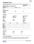
EQUIPMENT DATA
EQUIPMENT DESCRIPTION: DISPENSING SYSTEM, PRESCRIPTION, ROBOTIC, MODIFIED
ITEM SYMBOL: M7280A
MANUFACTURER: PARATA SYSTEMS
LOGCAT: C
EXT. DIM.: 87”H X 79 ½”W X 26 ½”D WEIGHT: 1,778 LBS.
SEISMIC: YES
HVAC:
HEAT GAIN (BTU/HR):
VENT SIZE:
CFM:
S.P:
HOT WATER
SIZE:
PRESSURE:
FLOW RATE:
TEMP.:
COLD WATER
SIZE:
PRESSURE:
FLOW RATE:
TREATED WATER
TYPE:
SIZE:
PRESSURE:
FLOW RATE:
STEAM
SIZE:
PRESSURE:
FLOW RATE:
DRAIN
SIZE:
RETURN
PUMPED:
GRAVITY:
SIZE:
REMARKS:
PLUMBING:
SIZE
TYPE
PRESSURE
OXYGEN:
AIR:
VACUUM:
N20:
NITROGEN:
GAS:
REMARKS:
ELECTRIC:
VOLTAGE: 120
AMPS: 20
WATTS:
PHASE: 1
HZ:
H.P.:
60
REMARKS:
SPECIAL REQUIREMENTS: DOORWAYS MUST BE AT LEAST 27" WIDE AND 80" HIGH TO PROVIDE
ADEQUATE CLEARANCE FOR THE MAX. THE MAX HOOD IS NOT INSTALLED UNTIL THE UNIT IS
POSITIONED IN PLACE; 80” IS SUFFICIENT HEIGHT FOR THE UNIT WITHOUT THE HOOD.UNIT. REQUIRES
OPERATING CONDITIONS OF 0-40° C WITH A HUMIDITY OF 20-80%. CIRCUIT MUST BE USED ONLY FOR
THE UNIT. CIRCUIT MUST TERMINATE IN A NEMA 5-20R RECEPTACLE; THE RECEPTACLE CAN BE
LOCATED NEAR THE FLOOR WITHIN 3' OF EITHER END OF THE MAX, OR IN THE CEILING ABOVE UNIT.
.
DATE: JUNE 3, 2011
JSN M7280A
Parata Systems - Circle of Pharmacy Care: Fill: Parata™ Max - The first and only next-generation pharmacy automation
JSN M7280A
CIRCLE OF PHARMACY CARE: FILL
Home
Parata Max™: Next-generation pharmacy automation
Circle of Pharmacy Care
Fill
Parata Max
Parata Mini
Parata RDS
Serve
Adhere
Long-Term Care
GREENGUARD Certification
Parata Difference
Contact Us
More Power, Less Time
Firstgeneration
technologies
HOW IT WORKS
In less than 30 minutes a day, your staff can equip Parata Max for
an uninterrupted day of dispensing.
require you to
adapt to them.
Nextgeneration
technologies
adapt to how
you use them.
Fill dispensing cells - 22 minutes*
With Parata Max, the first and only nextgeneration pharmacy automation, once-daily
maintenance is all that's needed to automate 60
percent of your total prescription volume.
Good to Great
Max builds on knowledge and experience Parata
gained safely dispensing 200 million prescriptions
Add caps - 30 seconds
in pharmacies across America with Parata RDS.
And, Parata Max enters the market with more
than 200 years of lifecycle testing already under
its belt.
"Now That's a No Brainer!"
The best innovations leave you scratching your
head and asking why it took so long to come up
with that idea! The power of Parata Max's
ingenuity is that it seems like such a "no-brainer"
when you see it in action.
Add vials - 30 seconds
Parata Systems - Circle of Pharmacy Care: Fill: Parata™ Max - The first and only next-generation pharmacy automation
Never before has automation been easier to
JSN M7280A
learn, use or maintain.
Once-Daily
No more hand-feeding caps and
Maintenance vials. Simply dump a full box into
Max's bins and you're good to go.
Clear unsorted prescription bin - 1 minute**
Parata's next-generation
dispensing cell boosts capacity by
30 percent, reducing
replenishment time, even for
bigger pills and bigger fills. And
super cells are now part of our
standard configuration.
Max holds 232 finished
prescriptions, a full day's volume
in most pharmacies.
Flexible
An innovative two-sided design
Design
segregates inventory from
dispensing activities to reduce
bottlenecks and open a world of
possibilities for installation and
workflow.
Max supports multiple vial sizes
and types.
Even the prescription drop-off
shelves can be customized to the
alphabetic mix of your customer
base.
An unsorted prescription bin that
holds 100 finished prescriptions
offers possibilities for off-hours
IVR processing, segregation of
late pick-ups, and other options to
suit your workflow.
Improved
Max maintains Parata's 100
Accuracy
percent accuracy for drug and
dose,* and raises counting
accuracy to about 10 times
current industry standards
* Parata automation uses bar-coding to verify a match
between the inventory bottle NDC, unique to medication and
strength, and the barcode on the dispensing cell. Parata
automation selects the correct cell for dispensing 100
percent of the time, ensuring accurate drug and total dosage.
* 2 minutes a cell, approximately 22 minutes a day in 250 script/day pharmacy
** Does not include time to transfer scripts for will call
JSN M7280A
Site Preparation Guide
120-0017 Rev 05
JSN M7280A
Site Preparation Guide
Copyright
© 2007-2010 Parata Systems LLC. All rights reserved.
No part of this documentation or the associated product may be reproduced, processed, duplicated
or published in any form by photocopying, microfilming, reprinting or other process, in particular
electronic means, without the written agreement of Parata Systems LLC.
Trademarks
AccuCount, AccuMed, APM, Automated Will Call, AutoScript III, Baker Cassette, Baker Cell, Baker
Universal, Baker Universal 2010, onePac, Parata, Parata and Design, Max, Mini, Parata Express,
Circle of Pharmacy Care, Circle of Pharmacy Care Fill Serve Adhere and Design, and Parata Puts You
Out In Front are trademarks or registered trademarks of Parata Systems LLC. AccuSign, AccuScript,
AutoLink, Drug Image Library, Drug Image Library and design and Pharmacy 2000 are trademarks
or registered trademarks of McKesson Automation Systems Inc. PACMED is a trademark of
McKesson Automation Inc.
Patents
Parata Systems LLC owns the following patents: US Patent Nos. 6,006,946; 6,036,812; 6,176,392;
6,464,142; 6,631,826; 6,681,149; 6,755,931; 6,775,589; 6,874,684; 6,892,780; 6,971,541;
6,971,544; 6,974,049; 6,974,050; 7,014,063; 7,016,766; 7,077,286; 7,093,755; 7,118,006;
7,139,639; 7,228,200; 7,263,411; 7,275,353; 7,289,879; 7,344,049; 7,410,098; 7,537,155;
7,555,362; 7,565,785; 7,565,782; 7,565,784; 7.581,373; 7,584,018; 7,596,932; also Patents
AU2002316746, AU2005306311, EP1409381, JP4027891, KR728814, MX268800,
PH12004500036, SG102742, CA2453404, CA2560056 and pending patent applications.
Third-Party Acknowledgments
Microsoft and Windows are registered trademarks or trademarks of Microsoft Corporation in the
United States and/or other countries. Other brands and their products are trademarks or registered
trademarks of their respective holders and should be noted as such.
United States Government Rights
Use, duplication or disclosure by the U.S. government is subject to the restrictions set forth in the
Parata Systems LLC Agreement and as provided in DFARS 227.7202-1(a), 227.7202-3(a) and
227.7202-4 (1998 ed., revised June 21, 2005), DFARS 252.227-7013(b)(3) and (c) (NOV 1995,
revised January 23, 2006), FAR 12.212(a) (1995), FAR 52.227-19, or FAR 52.227-14 (ALT III), as
applicable. Unpublished rights are reserved under the copyright laws of the United States.
Disclaimer
The information contained herein is considered accurate at the time of publication. Parata Systems
LLC reserves the right to make changes to the documentation or associated product at anytime
without notice.
Customer Care
1-888-PARATA-1
120-0017, Rev 05
JSN M7280A
Site Preparation Guide
Contents
Introduction ..................................................................................................................................1 Deciding on a location .................................................................................................................... 2 Max hood ................................................................................................................................ 2 Space requirements .............................................................................................................. 2 Special requirements ............................................................................................................ 2 Floor requirements ................................................................................................................ 3 Operating environment.......................................................................................................... 3 Planning a delivery route ................................................................................................................ 4 Installing power and data outlets ................................................................................................... 5 Max power requirements ...................................................................................................... 5 Max network requirements ................................................................................................... 5 Requirements for external printer and print server ............................................................. 7 Arranging for your pharmacy software to communicate with the Max......................................... 7 Assembling a drug list ..................................................................................................................... 8 Designating drugs for super cells ......................................................................................... 8 Obtaining supplies........................................................................................................................... 9 Starter Kit ............................................................................................................................... 9 Vial labels ............................................................................................................................... 9 Vials and caps ........................................................................................................................ 9 Planning for training ...................................................................................................................... 10 Basic training ....................................................................................................................... 10 Specialist training ................................................................................................................ 10 Class descriptions ................................................................................................................ 10 Implementation ......................................................................................................................... 11 Delivery .......................................................................................................................................... 11 Installation ..................................................................................................................................... 11 Assessing site readiness ..................................................................................................... 11 Performing the installation .................................................................................................. 12 Documentation and sign-off ................................................................................................ 12 Staff training .................................................................................................................................. 12 Attachments .................................................................................................................................1 Attachments
Site-Preparation Checklist
120-0017, Rev 05
i
JSN M7280A
Site Preparation Guide
Introduction
This document is intended to guide you as you prepare to install a Parata Max automated filling device in your pharmacy. It provides important information about preparing your site, ordering supplies, and planning for training and implementation. Parata Systems is committed to making your transition to an automated pharmacy system simple, quick and rewarding. If you have questions about any part of the implementation process, please contact a Parata implementation coordinator via phone, fax or email, as noted below. Phone:
Fax:
Email:
1-888-727-2821 (toll-free)
919-433-4303
[email protected]
120-0017, Rev 05
1
JSN M7280A
Site Preparation Guide
Preparing your
pharmacy
Deciding on a location
Max hood
87”
The Max is 87” high with the hood installed. If height is an issue, the hood can be omitted without adversely affecting system operation. The Max hood contains a HEPA filter and fan to help clean the interior of the unit in order to reduce upkeep for your staff. Additionally, it helps keep the system and its components at optimal temperature by cooling ambient air. 79 ½”
26 ½”
Figure 1: Max dimensions
Space requirements
The location where the Max is installed must accommodate: • Parata Max with hood:
79 ½" wide x 26 ½" deep x 87" high
NOTE: The height with the HEPA blower
assembly raised is 90 ½.”
• Parata Max:
• Minimum of 3’ clearance on each side (the “inventory
side,” where drug cells are located, and the
“prescription side,” where completed Rx orders are
delivered)
• Minimum of 3’ clearance on either end of the Max and
minimum of 1’ clearance on the other end
• Minimum of 1’ clearance above the Max, with 2’ to 3’
recommended
79 ½" wide x 26 ½" deep x 79 ½" high
NOTE: The Max is 97” wide with both
optional work shelves extended
Special requirements
• If there are sprinkler heads installed
near the Max location, consult local
building codes to ensure that there
will be enough clearance between
them and the Max.
120-0017, Rev 05
• Ensure that there will be enough clearance between
the Max and lights or other fixtures in the ceiling.
2
JSN M7280A
Site Preparation Guide
Floor requirements
Empty, the Max weighs approximately 1,778 pounds and rests on four leveling feet positioned near the corners of the unit, as shown in Figure 2, below. With pills, a Max containing 60 super cells weighs approximately 2,073 lbs. The pressure on each leveling foot pad is 422 psi (if the unit is resting evenly on all four feet) or 563 psi (if there are leveling issues and the unit is resting on three feet). We recommend that you check with your facilities manager or a building contractor to ensure that your floor can support the weight of the Max. The installation location must be level. Figure 2: Max footprint
Operating environment
• Operating temperature range: 55°‐80°F (12.8°‐26.7°C) • Operating humidity range: 30 to 70% relative humidity (non‐condensing) • The Max is designed to operate in ambient light, indoors. Do not locate the unit in direct sunlight or direct incandescent spot lights toward it. 120-0017, Rev 05
3
JSN M7280A
Site Preparation Guide
Planning a delivery route
The Max is delivered on a 20' to 60' air‐ride truck. If your location cannot accommodate a 60' delivery truck, contact Parata Implementation at 1‐888‐727‐
2821 immediately. NOTE
When you are considering whether you can accommodate a 60' truck, be sure to
allow adequate space for the truck to maneuver and unload the Max unit. The Max can be unloaded onto any solid, level surface (shipping dock, parking space, firm ground, etc.). Once the Max is unloaded, delivery representatives will uncrate it and roll it into position in your pharmacy. In preparation, you need to plan a route from the delivery area to the location where the Max will be installed. Factors to consider include: • Are all doorways on the route large enough to accommodate the Max? Doorways must be at least 27" wide and 80" high to provide adequate clearance for the Max. The Max hood is not installed until the unit is positioned in place; 80” is sufficient height for the unit without the hood. • Are there any corners that must be turned? If so, is there sufficient space to maneuver the Max (79 ½" long) around the corner? • Do any doorways have automatic door closers or other hardware that must be removed in order to get the Max through the door? • Are there shelves or other obstructions along the route that must be removed in order for the Max to pass? • Does the route include steps, thresholds, or other elevation changes that will require special tools or materials (e.g., ramp, planks, etc.)? • Does the route include carpeted areas or “spongy” flooring that will make it difficult to push the Max? A representative from the delivery company will visit your site a few days before the scheduled delivery to conduct a walk‐through of the planned route. 120-0017, Rev 05
4
JSN M7280A
Site Preparation Guide
Installing power and data outlets
In addition to the robotic system that fills prescriptions, a Max unit includes several other internal devices, including a label printer, an uninterruptible power supply (UPS), and two PCs. The power and data requirements described below apply to the Max unit as a whole (i.e., the Max unit and all its internal devices.) Max power requirements
We recommend that you check with your facilities manager or an electrical contractor to ensure that your site meets these specifications:
•
One 120V, 20A, 60Hz circuit
•
Circuit must be used only by the Max unit
•
Circuit must terminate in a NEMA 5-20R receptacle; the receptacle can
be located near the floor within 3’ of either end of the Max, or in the
ceiling above the unit. (See figure 6 on the next page.)
Figure 3:
NEMA 5-20R
receptacle
Max network requirements
To enable the Max to communicate with your pharmacy network, you must supply: •
•
•
An Ethernet cable terminating in an RJ-45 jack (Figure 4, right)
A 3’ RJ-45-to-RJ-45 (Ethernet) patch cable
An IP address on your pharmacy network
The RJ‐45 jack can be located near the floor at either end of the Max or in the ceiling above the unit. (See figure 6 on the next page.) 120-0017, Rev 05
Figure 4:
RJ-45 connection
5
JSN M7280A
Site Preparation Guide
Figure 6: Type and location of connections on the Max.
(Inset: Power and network requirements for external label printer and print server.)
Note: The power connection and Ethernet port you use can be in different locations
(e.g., one on top, the other on one end of unit); however, only one power connection
and one Ethernet port can be active at any time.
120-0017, Rev 05
6
JSN M7280A
Site Preparation Guide
Requirements for external printer and print server
In addition to its internal printer which generates vial labels, the Max also includes an external label printer and dedicated print server. The external printer allows you to print labels for the Max’s counting cells and prescription drop‐off shelves. As part of the Max installation process, a Parata‐certified installer will set up the external printer and print server in a location you designate. The two devices can be located anywhere in your pharmacy, as long as the necessary power and network connections are available (see below and Figure 6 inset on previous page). NOTE
The printer and print server must be connected to each other via a (supplied) USB
cable; however, they need not be in physical proximity to the Max unit. Considerations for location of external label printer & print server
Space requirements
•
•
Printer: approximately 5" x 5" x 7"
Print server: approximately 3" x 2 ¼" x 3/4"
Power requirements
•
Two standard 110VAC receptacles
(one for the printer; one for the print server)
Network requirements
•
•
•
An Ethernet port terminating in an RJ-45 port
An RJ-45-to-RJ-45 Ethernet cable
An IP address on your pharmacy network for the print server
Arranging for your pharmacy software to communicate with the Max
The software that provides the interface between your pharmacy software and the Max is different from the software that comes with the Max and is obtained from a separate pharmacy host‐software supplier. Please contact your host‐
software vendor for specifics on obtaining the vendor interface. To best prepare your software supplier for your Max implementation: • Give the supplier your Max installation date as soon as you receive it from Parata Implementation. • Get a work order and service contract from the supplier. • Verify that you have the latest software version or other requirements to support the Max. 120-0017, Rev 05
7
JSN M7280A
Site Preparation Guide
Assembling a drug list
As soon as possible, you should send your Parata implementation coordinator a list of the drugs you would like to dispense via the Max. We will analyze the list to determine which drug cells we can pre‐configure for you prior to delivery. NOTE
If your needs change at a later date, you can easily
reconfigure a drug cell to dispense a different drug.
We ask that you provide the list in Excel or Text (Notepad) format. A printed list is acceptable if neither of the electronic methods is possible. For information on how to generate the list, reference your host software user’s manual. For each drug on the list, please ensure that the report includes: • The drug’s NDC (full product code representing the actual product you currently carry on your shelf) • The drug name and strength • The number of prescriptions you dispensed for the drug during the time period covered by the report We recommend that you run your report for the past 90 days so that it includes data on 90‐day fills. Please ensure the report period is included with your data file or printed report. Designating drugs for super cells
Your pharmacy will receive a mix of super cells and standard cells with the Max. Each super cell can store 3.16 times the volume of a standard cell. Parata Systems created super cells to reduce replenishment frequency for: •
•
•
•
Large pills Frequently dispensed drugs Drugs whose inventory bottles hold more pills than a standard counting cell Medications prescribed for 90‐day counts or more After receiving your drug list, we will use the above criteria to help you decide which drugs are best suited to be your “super cell” drugs. 120-0017, Rev 05
8
JSN M7280A
Site Preparation Guide
Obtaining supplies
Starter Kit
The Max ships with a “Starter Kit” that contains some of the supplies you will need to get started using the Max. These items include Max documentation and training materials, cell and vial labels, and various cleaning supplies. You can order additional documentation and maintenance supplies from Parata Supply. Vial labels
Parata Supply also stocks vial labels for use in the Max, and can customize these labels to match your current labels. Your Parata implementation coordinator will provide you with a form where you can specify what types of information you want included on your labels. We also ask you to send sample labels for the following conditions: •
•
•
•
Regular label • Generic drug substituted Refills remaining • Multi‐vial label (if available) No refills remaining • PRN label Partial refill NOTE
The sample labels must be original printouts from your pharmacy label printer so that
our label design vendors can match your colors and graphics accurately.
Vials and caps
The Max is compatible with specific vials and caps from several vendors. Your Parata implementation coordinator will provide you with specifications and ordering information for each type. If your wholesaler does not currently carry Max‐compatible vials and caps, a representative from the vendor will contact your wholesaler to make the necessary arrangements. Please ensure that you receive an ample supply of vials and caps prior to your scheduled installation date. We recommend that you store them in a location where they will not be used before your scheduled installation but can be retrieved easily on installation day. NOTE
Please do not accept substitute items from your wholesaler.
Vials other than those specified by your Parata implementation
coordinator will not work properly in the Max.
120-0017, Rev 05
9
JSN M7280A
Site Preparation Guide
Planning for training
Basic training
Parata Systems will train up to 10 members of your pharmacy staff on basic Max operation. In order to provide each person with adequate hands‐on training time with the Max, we prefer to conduct the training in two groups, with no more than five people in each group. Each group will meet for one session. Specialist training
We recommend that you designate up to five (but no fewer than two) of the staff members who attend the “Basic” class to become “Parata Max Specialists.” Users who are Max Specialists receive special in‐depth training on the Max during a second session of training. These users are then prepared to take the lead among your staff in using and maintaining the Max. Class descriptions
Class
Who should attend
Topics included
Basic
Staff members whose primary interaction
with the Max will be filling prescriptions
during day-to-day operations.
• Parata Max operation
• Replenishment of consumables
• Bar code-scanning procedures
• Optimizing your workflow
• Hands-on practice
Specialist
Staff members who will be responsible for
keeping the Max running.
• Maintenance procedures
• Basic troubleshooting
• Reporting functions
• How to add new drugs
• How to calibrate drug cells
• Simulations of potential issues
• Hands-on practice
NOTE
To enhance the effectiveness of the training
and your satisfaction with the Max, please
ensure that the staff members selected for
training are not responsible for pharmacy
operations during their training sessions.
120-0017, Rev 05
10
JSN M7280A
Site Preparation Guide
Implementation
In general, our implementation schedule includes: • Delivery of the Max unit • Installation and drug set‐up for up to 100 drugs
NOTE A member of your pharmacy staff must participate in the drug set-up.
• Staff training Delivery
The Max will arrive at an agreed‐upon date and time. A delivery representative will unload the unit from the truck, uncrate it, and position it in your pharmacy. The delivery representative will have a “Delivery Verification Form” that lists tasks related to Max delivery. You or a representative from your pharmacy will be asked to initial the Delivery Verification Form at various times during the process to verify that specific tasks were performed. When the delivery process is complete, the delivery representative and a representative from your pharmacy will inspect your Max unit. Then both parties will sign the Delivery Verification Form to indicate that delivery is completed. Installation
Following delivery, a Parata‐certified installer will set up your Max unit. Assessing site readiness
As the first step of the installation process, the installer assesses the readiness of your site on six key points: •
Adequate space is available for installation and operation of the Max.
•
A 120V 20A 60Hz AC circuit terminating in a NEMA 5-20 receptacle has been installed per
electrical requirements.
•
An Ethernet cable with a RJ-45 jack has been installed per data requirements.
•
Any software upgrades/patches required for your pharmacy software (“Host”) to interface with the
Max have been installed.
•
Your store has an adequate supply of labels, vials, and caps.
•
Your drug inventory is organized to support efficient operation of the Max.
120-0017, Rev 05
11
JSN M7280A
Site Preparation Guide
Your site must meet each condition listed above in order to be considered ready for installation. If your site is not prepared, we reserve the right to reschedule the installation. In that case, a rescheduling charge will apply, per the Parata Purchasing Agreement. Performing the installation
The installation process includes inspecting, configuring, testing and calibrating the Max. During the installation process, the installer will help you load drugs in the Max. We will set up at least 10 drugs, and up to 100 if time permits. Documentation and sign-off
To prepare for the drug setup:
• Ensure that you have full bottles of the
drugs you want to dispense via the Max
on hand in time for the Max
installation.
• One or two days before your installation
date, set up your pharmacy software to
dispense the selected drugs via the
Max.
• Have a pharmacy specialist designated
to assist with the setup on installation
day. (Parata employees may not handle
the drugs directly, so someone from
your staff must participate in this
process.)
During the installation process, the installer will complete an Installation Authorization form, documenting that the site was prepared for installation and that installation tasks were performed. In the final section of the Parata Max Installation Authorization form, both the installer and a representative from your pharmacy will document the outcome of the installation. Then both parties will sign the Parata Max Installation Authorization form. Staff training
As described in the section titled “Planning for training,” a Parata‐certified trainer will train up to ten of your staff members (in two groups of up to five each) on the basic operation of the Max. We also provide advanced, “specialist” training for up to five staff members who have completed the basic class. Your Parata‐certified trainer or implementation coordinator will contact you the week before training to confirm a specific training schedule with you. 120-0017, Rev 05
12
JSN M7280A
Site Preparation Checklist
Use this checklist to keep track of site preparation tasks.
Timeframes are approximate.
30 days before scheduled delivery
Completed
Notes
1. Decide where the Max will be installed. Ensure that the selected
location has adequate space (including clearance around the
Max) and floor support for the Max.
2. Arrange for the Max’s power receptacle and circuitry to be installed.
3. Arrange for installation of a network (Ethernet) cable terminating
in an RJ-45 jack. Procure a 3’ RJ-45-to-RJ-45 patch cable.
4. Contact your pharmacy software vendor to obtain the appropriate
interface between your software and the Max.
5. Assemble list of drugs you want to dispense via the Max and forward
to your Parata Project Manager.
6. Provide sample labels (original printouts from your pharmacy label
printer) for the following conditions:
•
•
•
•
Regular label
Refills remaining
No refills remaining
Partial refill
• Generic drug substituted
• Multi-vial label (if available)
• PRN label
2 weeks before scheduled delivery
7. Decide which staff members will receive Basic and Specialist training.
8. Order Max-compatible vials and caps from wholesaler.
1 week before scheduled delivery
9. Expect delivery of vials and caps from wholesaler.
1-2 days before scheduled delivery
10. Review the planned delivery route with representative from delivery
company. (Delivery representative will contact you to schedule.)
11. Ensure that obstacles such as automatic door-closers, shelves,
etc. are removed from the delivery route.
12. Prepare the drugs you want to load into the Max during installation
and set up your pharmacy software to dispense those drugs from
the Max.
13. Ensure staff can locate your supply of Max-compatible vials and caps.
14. Decide where to locate the Max’s external printer and print server.
15. Obtain two static IP addresses on your pharmacy network (one
for the Max, one for the print server) from your IT staff.
120-0017, Rev C
Site Preparation Checklist, page 1 of 1
JSN M7280A
Parata Max® at Department of Defense sites
Network connectivity guide
Parata Max is a prescription-filling device that automates vial selection, vial labeling, pill
counting, vial capping and sorting of completed scripts into built-in shelving units by
patient last name for technician retrieval. Parata Max processes prescriptions rapidly with
consistent counting accuracy.
Parata Max helps pharmacists dispense medications more quickly, efficiently and
accurately than is possible by hand, while maintaining the direct pharmacist interaction
necessary to ensure patient safety. The operational workflow built into Parata Max ensures
that the pharmacy staff follows a repeatable process and provides safety features that help
pharmacists detect possible filling errors. The system’s built-in transaction accounting
provides the pharmacy with reportable transaction records.
Figure 1. Parata Max is an automated
medication-dispensing unit that fills
prescriptions according to data received
from the pharmacy host system. Parata Max
counts pills while dispensing them into a vial,
caps and labels the vial, and then places the
completed prescription into one of the dropoff bins for retrieval by the pharmacy staff.
The information in this document is proprietary and confidential to Parata
Systems LLC. Content may be changed at any time and without notice.
120-0159 Rev 02
© 2010 Parata Systems, LLC. All rights reserved.
page 1 of 7
JSN M7280A
Network Connectivity Guide for Parata Max® at DoD sites
System components
The internal components of a Max unit include:
• A primary and secondary CPU (“PC1” and “PC2”) that house the Parata Max software;
both CPUs are connected to the pharmacy network via a TCP/IP connection
• Drug cells that hold pill inventory and provide high-speed, accurate counting of pills;
an internal compressor provides high-pressure air to the drug cells
• Robotic technology that automates vial handling, capping and labeling
• A printer that prints prescription vial labels
• (2) touch screen monitors and (2) bar code scanners for interacting with the system’s
user interface
System components external to the physical Max unit include a print server and a bar code
printer. The print server connects to the pharmacy’s VLAN via a TCP/IP connection; the
bar code printer connects to the print server via a USB connection. Both of the Max unit’s
internal CPUs can access the bar code printer (via the pharmacy network) to generate
identification labels for the Max unit’s drug cells and drop-off shelves.
Pharmacy’s VLAN
TCP/IP
TCP/IP
TCP/IP
USB
User-interface devices
(Prescription side):
Touch-screen monitor
Bar code scanner
Pill-dispensing
technology:
Drug cells
Air compressor
Serial
Serial
Serial
USB
PC1
PC2
User-interface devices
(Inventory side):
Touch-screen monitor
Bar code scanner
Print
server
Bar
code
printer
Serial
Vial-handling
automation
Vial label
printer
Parata Max unit
Figure 2. Internal and external components of Parata Max.
120-0159 Rev 02
© 2010 Parata Systems, LLC. All rights reserved.
page 2 of 7
JSN M7280A
Network Connectivity Guide for Parata Max® at DoD sites
Parata Max software
The Parata Max software application exists only to control its internal pill-counting and
automation systems, and to provide the end user with the ability to interact with the Max
unit via a graphical user interface.
Primary internal components managed by the Max software application include: robotic
hardware and subsystems; a vial labeler system; an air compressor and drug cells; an
uninterruptible power supply (UPS); and the devices that provide input/output for the
end user (touch-screen monitors and bar code scanners).
The Max software application provides the end user access to information regarding the
status of filled and/or pending prescriptions, drug inventory and replenishment,
prescription volume and drug cell settings. The application does not provide the end user
any means to control systems or other applications external to the Max unit that may exist
on a given network.
Parata Max interfaces
The Parata Max interfaces can be divided into three categories: peripheral interfaces,
internal interfaces and external interfaces.
Peripheral interfaces refer to two USB ports that connect to the Max unit’s primary and
secondary CPUs. These USB ports are accessible only via a keyed door on the Max unit.
Parata personnel use the USB ports to attach a keyboard to the system when performing
initial installation, software updates and/or other maintenance.
Internal interfaces refer to the interactions between the primary and secondary CPUs
within the Max unit, and to the interactions between each CPU and the Max hardware.
Note: The primary and secondary CPUs communicate with each other across the pharmacy network, as
illustrated in Figure 4 and Figure 5; however, these communications are considered internal to Parata
Max since both CPUs are located within the physical Max unit.
External interfaces refer to communication with other systems or devices on the
pharmacy network:
• The Max unit’s primary and secondary CPUs can each access the external print server
and bar code label printer supplied with Parata Max. Additionally, the Max CPUs can be
configured to print reports to a network printer.
• Parata Max communicates with the pharmacy’s host system (CHCS); Parata Max may
also communicate with a workflow management system such as Pharmacy 2000™.
Communication with these external systems is accomplished via the AIM service
described below.
120-0159 Rev 02
© 2010 Parata Systems, LLC. All rights reserved.
page 3 of 7
JSN M7280A
Network Connectivity Guide for Parata Max® at DoD sites
AIM service
Parata’s Automation Interface Manager (AIM) service manages communication between
the Max unit and the pharmacy host system (CHCS). The AIM service may be installed
external or internal to the Max unit, as follows:
• For sites that use Pharmacy 2000 (version 6.0 or higher): The AIM service is installed
external to Parata Max, on the dedicated Pharmacy 2000 server.
• For sites that do not use Pharmacy 2000:
• If the site has more than one Parata automated filling device installed (either
multiple Max units, or one or more Max units in combination with other Parata
automated filling devices): The AIM service is installed external to Parata Max,
on a dedicated, Parata-provided “AIM box.” (See “DoD configuration for multiple
Parata Max units” on page 7.)
• If the site has only one Max installed, with no other Parata automated filling
devices: The AIM service is installed on the Max unit’s secondary CPU, i.e., on
“PC2.” (See “DoD configuration for a single Parata Max unit” on page 6.)
Handling of patient healthcare information (PHI)
Parata Max’s centralized architecture ensures that patient healthcare information (PHI) is
stored in a single, manageable location. For each prescription, PHI is stored in a database
until the prescription is filled and scanned. After the prescription request is completed
successfully, all patient-specific information is automatically deleted from the database.
Database backup
Parata Max performs an automatic, once-daily backup of its database. The database
backup location and the time when the daily backup occurs can be configured by Parata
or by the site’s IT staff. Users can also initiate a database backup manually via the user
interface.
Remote connectivity
Parata uses the B2B gateway to access devices on DoD networks remotely. Individual sites
must complete a defined B2B application process to allow remote access to Max units
installed at that site.
120-0159 Rev 02
© 2010 Parata Systems, LLC. All rights reserved.
page 4 of 7
JSN M7280A
Network Connectivity Guide for Parata Max® at DoD sites
IP address requirements
Two IP addresses for the Max unit
Each Parata Max contains two computers (referred to as “PC1” and “PC2”) that utilize the
Microsoft Windows XP™ operating system:
• PC1 houses the software for the Prescription side of the unit.
• PC2 houses the software for the Inventory side of the unit. When a single Max is the
only Parata automation installed at a site that does not use Pharmacy 2000, PC2 also
houses the AIM service (see page 4).
The IP addresses and ports for PC1 and PC2 are connected on a VLAN within the
Pharmacy network. Each PC requires a static IP address for communication to and from
the pharmacy host system; these IP addresses must be publicly routable to allow for
remote support via the B2B gateway.
One IP address for the print server
Each Max unit must have an external
label printer to print inventory cell
labels. The printer is connected to a
dedicated print server which requires a
static IP address supplied by the
customer. The external label printer
and print server are supplied by Parata
with each Max unit.
One IP address if AIM runs external to Max
When the AIM service is installed on
an external device (either a Pharmacy
2000 server or a dedicated AIM box),
the external device requires its own
static, B2B-compliant (i.e., publicly
routable) IP address.
120-0159 Rev 02
© 2010 Parata Systems, LLC. All rights reserved.
Figure 3. Parata provides an external
label printer and dedicated print server
for each Max unit. The site must provide
a static IP address for the print server.
page 5 of 7
JSN M7280A
Network Connectivity Guide for Parata Max® at DoD sites
System connection diagrams
DoD configuration for a single Parata Max unit
Figure 4 illustrates the system connections for a site using a single Parata Max unit.
The CHCS system sends prescription data to the Max unit via Parata’s AIM service
residing on PC2. The AIM service receives Rx fill data from CHCS on a port specified by
the site’s CHCS personnel. When the AIM service receives data from CHCS, it parses and
translates the data, and then sends it to the main Max application on PC1.
As the Max processes each script, PC1 sends status messages to the AIM service on PC2.
Examples of messages include acknowledgement of a fill request or cancel request; script
queued; script started; script completed (or script incomplete); and script picked up.
Figure 4. System connection diagram for a single Parata Max unit in a DoD environment.
(Note: This diagram shows a Max unit’s connections to and communication over the pharmacy
network. For a depiction of a Max unit’s internal connections, refer to Figure 2 on page 2.)
120-0159 Rev 02
© 2010 Parata Systems, LLC. All rights reserved.
page 6 of 7
JSN M7280A
Network Connectivity Guide for Parata Max® at DoD sites
DoD configuration for multiple Parata Max units
When more than one Parata automation device is present—either multiple Max units, or
one or more Max units in combination with other Parata automated filling devices—AIM
runs as an independent service on an external device:
• If a site uses Pharmacy 2000, AIM runs on the Pharmacy 2000 server.
• Otherwise, AIM runs on a Parata-supplied, dedicated CPU referred to as an “AIM box.”
As illustrated in Figure 5, the CHCS system sends prescription data to a Max unit via the
AIM service residing on the external device. The AIM service receives Rx fill data from
CHCS on a port specified by the site’s CHCS personnel.
When the AIM service receives Rx data from CHCS, it parses and translates the data,
selects a Max unit, and then sends the data to PC1 of the selected unit.
As the Max processes each script, PC1 sends status messages back to the AIM service on
the external device. Examples of messages include acknowledgement of a fill request or
cancel request; script queued; script started; script completed (or script incomplete); and
script picked up.
Figure 5. System connection diagram for multiple Parata Max units in a DoD environment.
(Note: This diagram shows each Max unit’s connections to and communication over the pharmacy
network. For a depiction of each Max unit’s internal connections, refer to Figure 2 on page 2.)
120-0159 Rev 02
© 2010 Parata Systems, LLC. All rights reserved.
page 7 of 7
U0037
EQUIPMENT DATA
EQUIPMENT DESCRIPTION: MESSAGING BOARD, PHARMACY WAITING AREA
ITEM SYMBOL: U0037
MANUFACTURER: ACF TECHNOLOGIES
LOGCAT: C
EXT. DIM.: REFER TO CUT SHEET
SEISMIC: NO
WEIGHT: 14 LBS
HVAC:
HEAT GAIN (BTU/HR)
VENT SIZE:
CFM:
S.P.
REMARKS:
PLUMBING:
HOT WATER
SIZE:
PRESSURE:
FLOW RATE:
TEMP.:
COLD WATER
SIZE:
PRESSURE:
FLOW RATE:
TREATED WATER
TYPE:
SIZE:
PRESSURE:
FLOW RATE:
STEAM
SIZE:
PRESSURE:
FLOW RATE:
DRAIN
SIZE:
RETURN
PUMPED:
GRAVITY:
SIZE:
SIZE
TYPE
PRESSURE
OXYGEN:
AIR:
VACUUM:
N20:
NITROGEN:
GAS:
REMARKS:
ELECTRIC:
VOLTAGE: 120
AMPS:
WATTS:
PHASE:
HZ: 60
H.P.:
1
REMARKS:
SPECIAL REQUIREMENTS:
ITEM REQUIRES A CONDUIT CONNECTION BETWEEN DISPLAY AND KEYBOARD. ITEM REQUIRES A
WALL RECEPTACLE NEAR THE DISPLAY CABINET. ITEM REQUIRES STRUCTURAL SUPPORT.
ITEM REQUIRES STRUCTURAL SUPPORT FOR INSTALLATION.
DATE: MAY 19, 2011
12:49 pm, Nov 14, 2011
Pharmacy Solutions
U0037
“
I NEED TO
take control
OF THE PATIENT FLOW IN MY PHARMACY
”
New Provider of Queuing and Take-a-Number Systems in the Naval Pharmacy Market
MANAGE THE FULL CYCLE OF YOUR PATIENT FLOW
ACF Technologies combines web-based software, non-proprietary
hardware devices and the highest level of service & support to offer
your pharmacy an innovative and cost-effective alternative to meet all
of your queuing needs.
Here are just some of the benefits of an ACF Solution:
• Web-based Queuing – One PC or server can drive all locations
• Non-Proprietary Hardware- Utilize off the shelf POS printers,
LCD monitors – Including OFF THE SHELF TICKETS!
• Non-Proprietary Database – You own your data!
• Call Patients Forward Using Naval Standard– Last Initial, last
four digits of the social security number (call out of order)
• Web-based TV Display – Does not require a PC or VGA Cables
• No Client Software – Easy to update, upgrade and service
• Innovative, Intuitive Software – Easy to use, manage and
interface (CHCS, McKesson, ScriptPro, Etc.)
• Excellent Customer/Technical Support – Instant response!
Our customers include:
• Navy Medical Center San Diego (13 Pharmacies)
• Navy Medical Center Portsmouth (8 Pharmacies, Labs, Clinics)
• Navy Medical Center Okinawa (2 Pharmacies)
• Naval Air Station Jacksonville (2 Pharmacies)
MAXIMIZE PATIENT THROUGHPUT through enhanced public guidance
systems, more effective patient reception, routing methodologies and smarter
utilization of staff resources.
ACCESS REAL-TIME METRICS that measure wait and transaction times, total
service time and abandonment/diversion rates. The ACF solution features easyto-use statistical tools that provide an enterprise view of productivity, service
and performance levels, customer flow patterns and more.
TRACK THE ENTIRE PRESCRIPTION FILL PROCESS along with the patient
flow. The ACF Solution utilizes MS SQL as its core database, which allows
pharmacies to port in real-time data from their automated distribution
applications. Pharmacy managers can now merge the two data sets allowing for
more enhanced oversight and benchmarking of organizational goals.
LAST INITIAL, LAST FOUR DIGITS OF THE SSN#
Q-Flow allows you to call patients to the counters using the
DOD standard identifier (last initial and last four digits of the
SSN) – printed on tickets, called through the voice system and
displayed on the TV monitors – allows you to call patients in
the order in which their prescriptions are filled
phone: 800.704.6592
www.acftechnologies.com
U0037
Utilizing state of the art software and expert industry knowledge, ACF Technologies can facilitate
the development of solutions that reduce patient cycle time, develop benchmarks for efficiency and
positively impact patient and staff satisfaction.
“
I NEED REAL TIME DATA
to benchmark
MY PHARMACY’S PERFORMANCE
PATIENT FLOW SOLUTIONS THAT FIT YOUR NEEDS
YOUR ENTIRE ENTERPRISE ON A SINGLE SERVER
ACF Technologies can support a distributed network of campuses,
registration areas, clinics and labs, all accessible through a standard
MS internet browser. This allows you to install, manage and support
your entire enterprise centrally through a single, secure (SSL
supported) and easy-to-update user interface.
PHARMACY SYSTEM INTERFACE - Because the ACF core
software application utilizes SQL Server as its database system,
it can easily port in data in real time from your MS SQL and
Oracle-based Prescription Filling Systems.
POST CALL DATA ON TV OR PLASMA SCREENS
While your patients are waiting for service, you
can post call forward data, important instructions,
information about your services, PowerPoints from
other clinics, even advertising from pharmaceutical
companies directly on TV monitors or plasma
screens in your lobby.
SELF SERVE KIOSK identifies and segments
your patients by rank and personal ID. The
patients are then provided with an appropriate
welcoming message and directed to the waiting
area.
SERVICE CONSOLE allows staff to effortlessly observe
waiting patients, call them forward and transfer to other
counters, consult rooms or other pharmacy facilities.
phone: 800.704.6592
www.acftechnologies.com
”
U0037
United States Navy Medical Center San Diego - Patient Flow Synopsis
Project History:
Dr. Michael Vancheri is the Director of Pharmacy for the entire USNMC SD system throughout the greater San Diego
area. He oversees every pharmacy in all 14 hospitals, dealing with largest volume of DOD patients in the entire United
States.
In 2005, the Command was becoming very unhappy with the level and quality of service currently being provided by
the Queuing system already in place. Not only did this system limit their ability to adapt to the great changes in their
patient flow caused by the large influx of service men and women and their families, but they were also having service
issues that caused the system to crash at inopportune times. In addition to this, they were not happy with the
customer-service afforded to them by the queuing company.
It was decided by leadership that a new system from another provider was warranted and they made initial contact
with ACF Technologies at this time. Because of the extremely large volume of patients (up to 3000 a week) they were
experiencing large wait times. This was compounded by the fact that the currently installed system slowed down some
of the back-end processes.
ACF’s solution was to install a system that would allow fluidity in the check-in area and allow for better segmentation
of the patients by rank. Also, ACF eliminated the reliance on a static ticketing scheme, an unfortunate deficiency in the
other system. This allowed the pharmacy to have up to 5 stations registering patients in times of great influx as well as
shift their counter configuration to better dispense the prescriptions.
Priority Calling By Rank
The NMCSD pharmacy prioritizes patients by rank, so certain types of patients need to have a higher priority than
others. Because the ACF solution is so adaptable, it can very easily accommodate any variation of services, priorities
and functions. Another advantage of the system immediately perceived by the command was not only its ability to
demonstrate in real time the current situation in the waiting area, but also to react and make changes in order to
further optimize the environment.
Call Patients Using “V-Number”
Because each patient’s prescription fill time varies, the pharmacy needed to come up with a scheme for calling
patients out of order. They also needed to way to relate the prescription fill system to the ACF system so that they
could call without having to cross-reference the two systems (another deficiency of the older queuing system). ACF
was easily able to accommodate this by integrating the DOD standard identification number scheme into the software.
This standard is the first initial of the last name and the last four digits of the social security number.
Now, when the counter sees that a prescription has been filled in the prescription system, they can choose the
corresponding number in the ACF system calling the patient forward. An added benefit to this is that the patients
waiting do not feel that they were skipped over because the numbers being called are not in numerical order.
Patient Flow Description:
• As the patients arrive, they approach the information desk
• The attendant ask what rank they are and issue a ticket for the particular service
• The ticket has a greeting message and their specific alphanumeric character (DOD Standard) The patients
would then be directed to the Registration waiting area where they can relax or fill out necessary paperwork
• While the patients are waiting, the ACF Media Player is programmed to display sequenced images, posters,
real-time scrolling messages, Cable TV, DVDs, even PowerPoint presentations
• When the Pharm-Techs in each of the counter-areas (a total of 12) are ready for the next patient, they press
“NEXT” on an on-screen software application
• The ACF Media Player will interrupt the feed to display a call message for a few moments. This call message
will then be cached into a line view showing the last 5-10 numbers called
Address: 35 Haywood St. Suite 209
Asheville, NC 28801
Office: 302.351.2594
Fax: 800.710.9842
1 of 2
Email: [email protected]
Web: www.acftechnologies.com
U0037
•
•
•
An audio unit then announces, “Now Serving Patient R2234 At Counter Number One” (or some variation)
over a speaker system
The patient then proceeds to the appropriate workstation and picks up their prescription
Managers for each of the areas are able to view and generate real-time and historical statistics reports based
on wait times, service times and staff productivity, as well as manage the counters in real time
Noted Benefits of the System Implementation:
• Immediate decrease in patient confusion about where to go or who is next in line
• Much more efficient and effective patient flow
• Metrics are available in real time as well as historically that display thresholds, wait times, transaction times,
staff productivity and due diligence
• Wait and Service time threshold notifications that alert the managers of excessive times respectively
• Plasma Monitor in the lobby can display DVD videos on a schedule about health subjects and benefits
available
• Cost savings from the use of non-proprietary hardware devices: ticket printers using non-proprietary paper
Recent Enhancements
Once the system was shown to enhance the flow of patients, the efficiency of the staff as well as save the pharmacy
money, NMCSD has expanded the application to all of the 13 remaining pharmacies in the San Diego system
including the Veteran’s Affairs pharmacy.
There is also considerable movement within these hospitals to expand to other clinics, labs and registration areas
within the NMCSD including Immunizations and Dental Health.
ACF has also developed a Live Search Tool that allows the manager to look up statistical details related to the
queuing system by name. This tool has provided a customer service benefit to the overall management process by
enabling the manager to type a complaining patient’s last name into a field and instantly pulling up information on their
visit (wait, transaction and prescription fill times and the technician who worked with them).
Another recent enhancement has allowed patients to check the status of their prescription-fills on a Touchscreen kiosk
by scanning the barcode on their tickets.
ACF Background
ACF Technologies, Inc. was founded in 2003 by queuing industry veterans with 20+ years of specialized combined
experience in the development and deployment of advanced customer and patient flow solutions. ACF’s goal was to
re-engineer the processes and methodologies lacking in the applications offered within the queuing industry.
ACF utilizes the most up-to-date development and architecture concepts and techniques to implement the first and
most advanced real-time, truly web-based, enterprise customer and patient flow automation tool in the US market.
ACF currently has installed Q-Flow Patient Queuing Systems in pharmacies, labs, immunization clinics and other
clinics at the Portsmouth Naval Medical Center, Okinawa Naval Medical Center and Jacksonville Naval Air
Station. Worldwide, ACF has nearly 500 queuing installations installed in organizations such as the US State Dept.,
the Dept. of Homeland Security, Boeing, healthcare enterprises, county Depts. of Health, private clinics, retail stores
and airports.
Address: 35 Haywood St. Suite 209
Asheville, NC 28801
Office: 302.351.2594
Fax: 800.710.9842
2 of 2
Email: [email protected]
Web: www.acftechnologies.com
U0037
ACF Technical Requirements for Q-Flow v5.x
Q-Flow Server Requirements
o
o
o
o
o
o
o
WEB - Windows 2003/2008 Server with IIS and ASP.net 2.0
DATABASE - MS SQL Server 2005 / 2008 including client components (i.e. MS SQL
Management Studio and Business Development Studio).
Default instance of Microsoft Reporting Services
Dot.Net 3.5 framework (SP1)
Min Server specs: 4 gig RAM, Pentium Dual Core+
Requires a fixed IP address for server(s)
ACF supports a VM environment for Q-Flow
Workstation PC
For the workstation PCs or thin clients:
o Must have network access to server
o Internet Explorer 6.0+ / 7.0+
o For viewing Q-Flow Reports, the server hosting Reporting Services must be included in trusted
sites of Internet Explorer
Q-Flow Topology Overview
Address: 35 Haywood Rd. Suite 209
Asheville, NC 28801
Office: 302.351.2594
Fax: 800.704.6592
1 of 4
Email: [email protected]
Web: www.acftechnologies.com
U0037
Other Common Hardware Considerations at Each Branch
NOTE: all hardware is commercially available
Ticket Printer
o Host PC if USB printer
o Network access with fixed IP if Network Printer
Self-Serve Kiosk
o Requires mounting location (wall or pillar, or freestanding if unit permits)
o Network access with fixed IP Address
o IE 6.0+ / 7.0+ browser
o 1 GB RAM
Video and Audio System
o The Media Player PC – MS Windows XP Pro+, Pentium-based processor w/ 1GB RAM
o MS Windows Media Player v11
o VGA and Audio over CAT 5/6 converters (requires power)
o Network connection with a fixed IP
LCD TV Monitor
o VGA / HDMI input and 1/8 inch din sound input.
o Cable TV / Satellite signal at site of Media Player if live TV overlay is desired
Display Setup Diagram 1.1
Address: 35 Haywood Rd. Suite 209
Asheville, NC 28801
Office: 302.351.2594
Fax: 800.704.6592
2 of 4
Email: [email protected]
Web: www.acftechnologies.com
U0037
Display Setup Diagram 1.2
Video Signal Extensions setup (Diagram 1.3)
Remote Unit
CAT 5 signal to VGA signal
Point To Point CAT 5
wiring No Switching
Address: 35 Haywood Rd. Suite 209
Asheville, NC 28801
Local Unit Converts VGA
to CAT 5
Office: 302.351.2594
Fax: 800.704.6592
3 of 4
Email: [email protected]
Web: www.acftechnologies.com
U0037
VGA-To-CAT 5 Converter Close up (Diagram 1.4)
Address: 35 Haywood Rd. Suite 209
Asheville, NC 28801
Office: 302.351.2594
Fax: 800.704.6592
4 of 4
Email: [email protected]
Web: www.acftechnologies.com
U0037
PROPOSED WORKFLOW WITH SCREEN SHOTS
Step 1: Patient Reception at the Touchscreen Kiosk
NOTES:
-
Screen design is fully customizable
-
Multi-screen design is typical
-
Multi-lingual options
-
One Touch philosophy embraced
-
Scanners may be incorporated
-
Tickets are fully customizable, including Wayfinding Directions
Address: 35 Haywood Rd. Suite 209
Asheville, NC 28801
Office: 404.452.8597
Fax: 800.704.6592
1 of 6
Email: [email protected]
Web: www.acftechnologies.com
U0037
Step 2: Staff Calls Patient by Clicking NEXT
Notes:
-
Service Console shows list of all waiting patients according to queue
-
Service Console may be filtered according to Function (i.e. Job Role)
-
NEXT Button is driven by configured automation, incl. BQ Threshold
Address: 35 Haywood Rd. Suite 209
Asheville, NC 28801
Office: 404.452.8597
Fax: 800.704.6592
2 of 6
Email: [email protected]
Web: www.acftechnologies.com
U0037
Step 3: When Staff Clicks NEXT, Audio and Video Message Appears on
TV alongside Cable TV or Announcements
NOTES:
-
Content Frame (right frame) may be configured for CATV, Slides, or dynamic
-
Font Sizes are adjustable
-
Frame layouts are based on template designs included from ACF
-
Typical layout includes:
o Left Frame for calling patients
o Right Frame for Dynamic Content
o Scrolling Ticker for info, RSS, or Announcements
Address: 35 Haywood Rd. Suite 209
Asheville, NC 28801
Office: 404.452.8597
Fax: 800.704.6592
3 of 6
Email: [email protected]
Web: www.acftechnologies.com
U0037
o Banner for Branding
Step 5: Agent Advances Patient to Next Service using Routes
NOTES:
-
Agents have on-screen access to wait times for all services
-
Patient keeps original ticket – all transfers documented and reportable for “Entry to
Exit” patient experience
-
Transfers can be “rules based” to ensure proper regimented workflow (including
dependencies)
-
Transfers can incorporate User Permissions (e.g. Pharmacy Tech can’t escalate
patient to LAB STAT queue)
-
Transfers can offer Patient Control via simple barcode scanning (e.g. Patient may
want to stop at café before proceeding to lab – transfer is performed in EXPECTED
status until patient scans ticket to trigger WAITING status)
Address: 35 Haywood Rd. Suite 209
Asheville, NC 28801
Office: 404.452.8597
Fax: 800.704.6592
4 of 6
Email: [email protected]
Web: www.acftechnologies.com
U0037
Step 5: Managers may View Real Time Dashboards and Reports
NOTES:
-
All data is centralized on a single database
-
Reporting levels are based on permissions and enterprise hierarchy (e.g. Lab
Manager can’t run reports on Pharmacy, but CIO can run reports across entire
organization)
-
Includes ACF Canned Reports, plus ad-hoc reporting via MS SQL Server Reporting
Services
Address: 35 Haywood Rd. Suite 209
Asheville, NC 28801
Office: 404.452.8597
Fax: 800.704.6592
5 of 6
Email: [email protected]
Web: www.acftechnologies.com
U0037
-
Reports are Real Time (i.e. Dashboards) and historical
Additional Report Examples
Queue Dashboard
Service Performance Distribution
Address: 35 Haywood Rd. Suite 209
Asheville, NC 28801
Office: 404.452.8597
Fax: 800.704.6592
6 of 6
Email: [email protected]
Web: www.acftechnologies.com
EQUIPMENT DATA
EQUIPMENT DESCRIPTION: MESSAGING BOARD, QUEUING KIOSK, PHARM WAITING AREA
ITEM SYMBOL: U0037A
MANUFACTURER: ACF TECHNOLOGIES
LOGCAT: C
16.56"W
X 10.5"D WEIGHT:
109 LBS.
EXT DIM: 57.3"H
REFERXTO
CUT SHEET
WEIGHT:
SEISMIC: NO
YES
HVAC:
HEAT GAIN (BTU/HR)
VENT SIZE:
CFM:
S.P.
REMARKS:
PLUMBING:
HOT WATER
SIZE:
PRESSURE:
FLOW RATE:
TEMP.:
COLD WATER
SIZE:
PRESSURE:
FLOW RATE:
TREATED WATER
TYPE:
SIZE:
PRESSURE:
FLOW RATE:
STEAM
SIZE:
PRESSURE:
FLOW RATE:
DRAIN
SIZE:
RETURN
PUMPED:
GRAVITY:
SIZE:
SIZE
TYPE
PRESSURE
OXYGEN:
AIR:
VACUUM:
N20:
NITROGEN:
GAS:
REMARKS:
ELECTRIC:
VOLTAGE: 120
AMPS:
PHASE:
HZ: 60
1
8
WATTS:
H.P.:
REMARKS:
SPECIAL REQUIREMENTS:
ITEM
REQUIRES
A DATACONNECTION
PORT AND A
FLOOR DISPLAY
DUPLEX
RECEPTABLE.
REQUIRES
ITEM REQUIRES
A CONDUIT
BETWEEN
AND
KEYBOARD. ITEM
REQUIRES A
CONNECTIVITY
TO
THETHE
QUEUE
SYSTEM.
WALL RECEPTACLE
NEAR
DISPLAY
CABINET. ITEM REQUIRES STRUCTURAL SUPPORT FOR
INSTALLATION.
DATE: JULY 13, 2011
1:22 pm, Jul 13, 2011
THE
STEALTH SERIES
KIOSK
A WOLF IN SHEEP’S CLOTHING
Designed for
style and
engineered
for high
performance!
The Stealth Series provides a line of elegant and fully functional interactive kiosks. Sleek in
appearance, this kiosk fits into almost any environment and is available in a variety of finishes
and colors to creatively enhance any self-service venue.
The Stealth combines a compact footprint and rugged field performance with standard model
economy. This series offers generous LCD size, rugged keyboard and trackball options, and is
available with a full range of overhead and panel signage to add visual impact to your
application. Outdoor model options enable an expanded customer reach to an open-air
self-service environment.
One of KIOSK's most popular and widely deployed
models, the Stealth features hinged doors and readily
accessible components for simple and efficient field
maintenance. Custom graphic options emphasize
corporate branding and provide optimal visibility for
quick consumer adoption.
Inside, this kiosk is designed to accept a wide
variety of optional components from biometrics
to printers, monitors to card readers. Reliable
and tested components.
See reverse for a detailed list of Stealth Series models,
specifications and dimensions.
ISO 9001:2000 Certified
FOR MORE INFORMATION CALL TOLL FREE: 800.509.5471
OR VISIT US ONLINE AT WWW.KIOSK.COM
T H E S T E A LT H S E R I E S : M O D E L S , S P E C I F I C AT I O N S A N D D I M E N S I O N S
STEALTH SERIES
STANDARD CONFIGURATION:
DIMENSIONS:
OPTIONAL COMPONENTS:
• Durable Powder Coated Steel Enclosure
• Celeron or Pentium Dual Core Computer
Genuine Intel Processor
• Dual Amplified Speakers
• 17" or 19" LCD Display (17" shown L, 19" R)
• Touch Screen
•
•
•
•
16.56" Wide
53.7" Tall
10.5" Deep
Weight: 105 lbs
109 lbs for 19" LCD Display
• Base Plate: 21" W, 17.5" D
• Overhead Base Plate:
26" W, 26.1" D
• 19" Overhead Display*
• Durable Powder Coated Steel Enclosure
• Celeron or Pentium Dual Core Computer
Genuine Intel Processor
• Dual Amplified Speakers
• 17" or 19" LCD Display (17" shown L, 19" R)
• Rugged Keyboard and Trackball
•
•
•
•
16.56 " Wide
53.7" Tall
16.9" Deep
Weight: 113 lbs
117 lbs for 19" LCD Display
• Base plate 21" W, 17.5" D
• Overhead Base Plate:
26" W, 26.1" D
•
•
•
•
• Durable Powder Coated Steel Enclosure
• Celeron or Pentium Dual Core Computer
Genuine Intel Processor
• Dual Amplified Speakers
• 17" or 19" LCD Display (17" shown L, 19" R)
• Touch Screen
•
•
•
•
16.56" Wide
53.7" Tall
10.5" Deep
Weight: 105 lbs
109 lbs for 19" LCD Display
• Base Plate: 21" W, 17.5" D
• Overhead Base Plate:
26" W, 26.1" D
•
•
•
•
•
• Durable Powder Coated Steel Enclosure
• Celeron or Pentium Dual Core Computer
Genuine Intel Processor
• Dual Amplified Speakers
• 17" or 19" Sunlight Readable LCD Display
• Rugged Touch Screen
• Weather-Seal Protection
•
•
•
•
•
20.7" Wide
54" Tall
13.7" Deep
Weight: 130 lbs
Base Plate: 23.4” W, 19" D
• MSR Smart Card Reader
• Receipt Printer
• 8.5" Wide Thermal printer
• Durable Powder Coated Steel Enclosure
• Celeron or Pentium Dual Core Computer
Genuine Intel Processor
• Dual Amplified Speakers
• 17" or 19" Sunlight Readable LCD Display
• Rugged Keyboard and Trackball
• Weather-Seal Protection
•
•
•
•
•
20.7" Wide
54" Tall
20" Deep
Weight: 138 lbs
Base Plate: 23.4” W, 19" D
• MSR Smart Card Reader
• Receipt Printer
• 8.5" Wide Thermal printer
19" Overhead Display*
Touch Screen
8.5" Wide Thermal printer
80mm or 112mm
Thermal Printer
19" Overhead Display*
1D / 2D Barcode Reader
MSR Smart Card Reader
8.5" Wide Thermal printer
80mm or 112mm
Thermal Printer
• Rugged Keyboard and
Trackball
Sheltered Outdoor
Sheltered Outdoor
*19" Overhead Height 70.3", Width 17.5," Incremental 25 lbs.
ADDRESS: 346 SOUTH ARTHUR AVENUE • LOUISVILLE, CO 80027
PHONE: 303.466.5471 • TOLL-FREE: 1.800.509.5471
FAX: 303.466.6730 • EMAIL: [email protected] • WEB: WWW.KIOSK.COM
8
7
6
5
1
3
4
REVISIONS
REV
1.0
DESCRIPTION
ENG
K12092
BAM
17.560
DATE
5-16-11
D
D
17 INCH LCD
PRINTER (KR203)
3.440
BACK PACK
C
2X SPEAKERS
C
12.873
54.836
PRINTER (KR203)
FRONT FACE CUTOUT
PAPER 8 INCH ROLL
7.000
B
CONSIGNED PC
B
6. ALL STUDS TO BE INSERTED ALMOST FLUSH AND THEN GROUND
AND SANDED FLUSH TO METAL.
5. ALL EDGES TO BE FREE OF SHARP EDGES AND BURRS.
4. TOLERANCES: .005 FEATURE.
.010 FEATURE TO FEATURE.
.015 FEATURE TO BEND.
.020 BEND TO BEND.
3. NEXT ASSEMBLY:
2. FINISH:
1. MATERIAL:
NOTES: UNLESS OTHERWISE STATED.
ALL DIMENSIONS. ARE IN
346 S ARTHUR AVE.
INCHES UNLESS OTHERWISE
LOUISVILLE, CO 80027
SPECIFIED.
PART DESCRIPTIONTHIS DRAWING IS
THE PROPERTY OF
CONCEPT DWG ACF Tech
KIOSK INFORMATION
SYSTEMS, INC.
A
ENGINEERDATE-
7
6
5
4
3
PART NUMBER-
BAM
K12092
REV-
5-16-11
2
1
1.0
A
EQUIPMENT DATA
EQUIPMENT DESCRIPTION: MESSAGING BOARD, MONITOR, QUE SYSTEM
ITEM SYMBOL: U0037B
MANUFACTURER: ACF TECHNOLOGIES
LOGCAT: C
EXT DIM: 18.9”H X 31.1”W X 5.5”D
WEIGHT: 35.3
SEISMIC: YES
HVAC:
HEAT GAIN (BTU/HR)
VENT SIZE:
CFM:
S.P.
REMARKS:
PLUMBING:
HOT WATER
SIZE:
PRESSURE:
FLOW RATE:
TEMP.:
COLD WATER
SIZE:
PRESSURE:
FLOW RATE:
TREATED WATER
TYPE:
SIZE:
PRESSURE:
FLOW RATE:
STEAM
SIZE:
PRESSURE:
FLOW RATE:
DRAIN
SIZE:
RETURN
PUMPED:
GRAVITY:
SIZE:
SIZE
TYPE
PRESSURE
OXYGEN:
AIR:
VACUUM:
N20:
NITROGEN:
GAS:
REMARKS:
ELECTRIC:
VOLTAGE: 120
PHASE:
1
AMPS:
WATTS: 140
HZ: 60
H.P.:
REMARKS:
SPECIAL REQUIREMENTS:
ITEM REQUIRES A CONDUIT CONNECTION BETWEEN DISPLAY AND KEYBOARD. ITEM REQUIRES A WALL
RECEPTACLE NEAR THE DISPLAY CABINET. ITEM REQUIRES STRUCTURAL SUPPORT FOR INSTALLATION.
DATE: JULY 13, 2011
U0037B
Large-Screen Display
NEC MultiSync® Large-Screen LCD Series
32” (31.5” VIS), 40”, 46” and 57” LCD displays
ideal for digital signage applications
Airports/flight and
baggage information
Digital
merchandising
Corporate
Also serving
markets such as...
Restaurants
www.necdisplay.com
Medical
Financial
Theaters
Tradeshows Broadcasting
U0037B
User-friendly, efficient design. As ease of installation is a main
concern for the information display market, these displays were
designed with light weight in mind, making them simple to transport and install wherever necessary. In addition, NEC is on the
forefront of mounting technology as the displays’ cabinets were
designed to meet currently proposed VESA mounting standards
for larger-sized public displays, which will be required of all
manufacturers in the future. Their ability to be mounted in either
portrait or landscape orientation further adds to your flexibility.
With a uniformly thin frame, the displays’ designs are ideal for
multi-screen construction for virtually seamless video walls.
Simplified control of screen settings. For quick and easy setups,
a multitude of presets, including automatic image adjust and
automatic input detect, make MultiSync Large-Screen LCDs ready
to go right out of the box. Their factory reset feature even allows
you to return to the display’s original settings if desired.
Intelligent power management ensures a smart investment. Utilizing energy-efficient technologies in their design, these displays reduce power consumption and significantly lower your total cost of
ownership (TCO). The high-efficiency backlight reduces not only
the power consumption but also the heat generation at the front
of the screen, while the real-time clock’s sleep/wake management
scheduler improves energy savings and extends display life. In addition, the MultiSync LCD4020 and LCD4620 have been designed
with two thermally controlled fans. Based on default temperature
set points (or user-defined settings), sensors continuously monitor
the interior temperature of the display. When the set temperature
level is reached, the fans cool the display to the desired level. In
cases in which the fans are unable to cool down the display, the
backlights are dimmed or, as a last resort, the display is automatically shut down.
Figure 1
LCD4020/LCD4620
AC IN
DVD/HD IN
RGB/HV OUT
R
G
B
H
V
HDMI
Y
Cb/Pb
VIDEO
Cr/Pr S-VIDEO IN
AUDIO
OUT
AUDIO OUT
R
R
L
L
SPEAKER
R
L
DVI(DVI-D)
IN
R
G
B
H
RGB/HV IN
V
AUDIO3 IN AUDIO2 IN
AUDIO1 IN
IN
PC IN
LCD5710
-
-
VGA(D-SUB)
-
MultiSync Large-Screen
LCDs feature a number
of input connectors for
maximum compatibility.
This makes it possible
to upgrade adapters or
software without having to
purchase a new display.
LCD3210
1. AC IN connector Connects with the supplied power cord.
2. RGB 1 IN (DVI-D) To input digital RGB signals from a computer*
* This connector does not support analog input.
3. RGB 2 IN (mini D-Sub 15 pin) To input analog RGB signals from a
personal computer or other RGB equipment.
4. RGB 3 DVD/HD [R, G, B, H, V] (BNC) To input the analog RGB
signals or signals from other RGB equipment. A Sync-on-Green
signal can be connected to the G connector.
5. RGB OUT connector (mini D-Sub 15 pin) To output the signal from
the RGB 2 or 3 IN connector.
6. DVD/HD CONNECTOR (BNC) Connecting equipment such as a
DVD player, HDTV device or laser disc player.
7. AUDIO IN 1,2,3 Input audio signal from external equipment such
as a computer, VCR or DVD player.
8. AUDIO OUT Output the audio signal from the selected AUDIO IN
source.
Denotes an AV unit function.
All AV functions are enabled when the AV unit is installed.
9. VIDEO INPUT/OUTPUT CONNECTOR
VIDEO IN connector (BNC and RCA): Input a composite video
signal. BNC and RCA are not available at the same time. (Use only
one input).
VIDEO OUT connector (BNC): Output the composite video signal
from the VIDEO IN source.
S-VIDEO IN connector (DIN 4 pin): Input the S-video (Y/C separate
signal).
10. EXTERNAL CONTROL (mini D-Sub 9 pin) RS-232C Input signal
from control equipment such as a computer.
In connector: Input signal from control equipment such as a
computer or the output from a different MultiSync LCD3210/
LCD4020/LCD4620
LCD4610/LCD4010 only - Out connector: To connect multiple
MultiSync LCD4020/LCD4620
11. EXTERNAL SPEAKER TERMINAL Outputs the audio signal from
the selected audio source.
12. HDMI CONNECTOR To input digital HDMI signals.
13. EXPANSION SLOT To connect ATSC/NTSC/QAM tuner or other
third-party components
Display
Viewable Size Image
Pixel Pitch
Pixels Per Inch
Brightness (typical)
Contrast Ratio (typical)
Viewing Angle (typical)
Response Time (typical)
Display Colors
Active Screen Area (W X H)
Bezel Width (L/R, T/B)
Screen Aspect Ratio
Synchronization Range
Horizontal
Vertical
Input Signal
Video
Input
U0037B
Model
LCD3210-BK (LCD3210-BK-IT)
LCD4020-BK-AV (LCD4020-BK-IT)
LCD4620-BK-AV (LCD4620-BK-IT)
LCD5710-BK (LCD5710-BK-IT)
31.5"
0.511
50 @ native resolution
500 cd/m2
600:1
176° Vert., 176° Hor.
(88U/88D/88L/88R)@ CR>10
Rapid Response (18ms)
256 RGB Level, more than 16 million
760 x 450mm
45.66mm, 43.372mm
16:9
40"
0.648mm
40 @ native resolution
500 cd/m2
1200:1
178° Vert., 178° Hor.
(89U/89D/89L/89R)@ CR>10
Rapid Response (16ms)
256 RGB Level, more than 16 million
886.5 x 497.8mm
15.5mm, 15.5mm
16:9
46"
0.746mm
34 @ native resolution
500 cd/m2
1200:1
178° Vert., 178° Hor.
(89U/89D/89L/89R)@ CR>10
Rapid Response (16ms)
256 RGB Level, more than 16 million
1018.5 x 574mm
16.5mm, 17mm
16:9
57"
0.6525mm
39 @ native resolution
450 cd/m2
900:1
178° Vert., 178° Hor. (89U/89D/89L/
89R)@ CR>10
Rapid Response (16ms)
256 RGB Level, more than 16 million
1252.8 x 704.7mm
52.5mm, 44mm
16:9
-15.625, 15.744, 31.5-91.1 KHz (Analog,
LCD3210-BK)/-31.5-91.1 KHz (Analog,
LCD3210-BK-IT)/-31.5-91.1 KHz (Digital)
50-85 Hz Analog/Digital
-15.625, 15.744, 31.5-91.1 KHz (Analog,
LCD4020-BK-AV)/-31.5-91.1 KHz (Analog,
LCD4020-BK-IT)/-31.5-91.1 KHz (Digital)
50-85 Hz Analog/Digital
-15.625, 15.744, 31.5-91.1 KHz (Analog,
LCD4620-BK-AV)/-31.5-91.1 KHz (Analog,
LCD4620-BK-IT)/-31.5-91.1 KHz (Digital)
50-85 Hz Analog/Digital
-15.625, 15.744, 31.5-91.1 KHz (Analog,
LCD4610-BK)/-31.5-91.1 KHz (Analog,
LCD4610-BK-IT)/-31.5-91.1 KHz (Digital)
50-85 Hz Analog/Digital
ANALOG RGB 0.7 Vp-p / 75 Ohms
ANALOG RGB 0.7 Vp-p/75 Ohms,
Digital, S-Video, HDMI, Composite,
Component, Audio
Separate sync: TTL Level
(Positive/Negative)
Composite sync: TTL Level
(Positive/Negative)
Composite sync on green:
(0.3Vp-p negative 0.7Vp-p positive)
ANALOG RGB 0.7 Vp-p/75 Ohms,
Digital, S-Video, HDMI, Composite,
Component, Audio
Separate sync: TTL Level
(Positive/Negative)
Composite sync: TTL Level
(Positive/Negative)
Composite sync on green:
(0.3Vp-p negative 0.7Vp-p positive)
ANALOG RGB 0.7 Vp-p / 75 Ohms
DVI-D
Analog D-sub
Analog BNC
Composite (Shared RCA and BNC),
S-Video, HDMI
Component (RCA)
Audio 1 (minijack), Audio 2 and 3 Stereo
(RCA), HDMI
Internal Speaker: None
RS232, DDC/CI
DVI-D
Analog D-sub
Analog BNC
Composite RCA or S-Video
Sync
Separate sync: TTL Level
(Positive/Negative)
Composite sync: TTL Level
(Positive/Negative)
Composite sync on green:
(0.3Vp-p negative 0.7Vp-p positive)
RGB1
RGB2
RGB3
Video 1*
DVI-D
Analog D-sub
Analog BNC
Composite RCA or S-Video
Component Video 1 (DVD/HD)*
Audio*
DVI-D
Analog D-sub
Analog BNC
Composite (Shared RCA and BNC),
S-Video, HDMI
Component (RCA)
Audio 1 (minijack), Audio 2 and 3 Stereo
(RCA), HDMI
Internal Speaker: None
RS232, DDC/CI
Separate sync: TTL Level (Positive/Negative)
Composite sync: TTL Level (Positive/
Negative)
Composite sync on green: (0.3Vp-p negative 0.7Vp-p positive)
External Control
Component BNC
Audio 1 (minijack), Audio 2 and 3 Stereo
(RCA)
Internal Speaker: None
RS232, DDC/CI
Output
RGB
Video*
Audio*
Control
Audio Amplifier*
Daisychain RGB3
Daisychain Video1
Daisychain - Selected Audio in
RS232 for multiple monitor control
7W x 7W
Daisychain BNC - RGB3
Daisychain BNC (Composite) - Video1
Daisychain - Mini Pin Jack
RS232 for multiple monitor control
15W x 15W
Daisychain BNC - RGB3
Daisychain BNC (Composite) - Video1
Daisychain - Mini Pin Jack
RS232 for multiple monitor control
15W x 15W
Daisychain RGB2, RGB3
Daisychain Video1
Daisychain - Selected Audio in
RS232 for multiple monitor control
7W x 7W
Resolutions Supported
720 x 400 @ 70-85 Hz
640 x 480 @ 60-85 Hz
800 x 600 @ 50-85 Hz
832 x 624 @ 74.5 Hz
1024 x 768 @ 50-85 Hz
1280 x 1024 @ 50-85 Hz
1600 x 1200 @ 60 Hz (Compressed)
1280 x 768 @ 50-85 Hz
1360 x 768 @ 50-85 Hz
NTSC/PAL, SECAM, 4.43 NTSC, Pal60
HDTV, 480i, 480p, 720p, 1080i (not
available on LCD3210-BK-IT)
640 x 400 @ 56.2 Hz
720 x 400 @ 70-85 Hz
640 x 480 @ 50-85 Hz
800 x 600 @ 50-85Hz
832 x 624 @ 74.5 Hz
1024 x 768 @ 50-85 Hz
1152 x 870
1600 x 1200 @ 50-85 Hz
1280 x 768 @ 50-85 Hz
1360 x 768 @ 50-85 Hz
1920 x 1080 @ 60Hz (compressed)
NTSC/PAL, SECAM, 4.43 NTSC, Pal60
HDTV, 480i, 480p, 720p, 1080i, 1080p
(not available on LCD4020-BK-IT)
640 x 400 @ 56.2 Hz
720 x 400 @ 70-85 Hz
640 x 480 @ 50-85 Hz
800 x 600 @ 50-85 Hz
832 x 624 @ 74.5 Hz
1024 x 768 @ 50-85 Hz
1152 x 870
1600 x 1200 @ 50-85 Hz
1280 x 768 @ 50-85 Hz
1360 x 768 @ 50-85 Hz
1920 x 1080 @ 60 Hz (compressed)
NTSC/PAL, SECAM, 4.43 NTSC, Pal60
HDTV, 480i, 480p, 720p, 1080i, 1080p
(not available on LCD4620-BK-IT)
720 x 400 @ 70-85 Hz
640 x 480 @ 60-85 Hz
800 x 600 @ 50-85 Hz
832 x 624 @ 74.5 Hz
1024 x 768 @ 50-85 Hz
1280 x 1024 @ 50-85 Hz
1600 x 1200 @ 60 Hz (Compressed)
1280 x 768 @ 50-85 Hz
1360 x 768 @ 50-85 Hz
1920 x 1080 % 50-60 Hz
NTSC/PAL, SECAM, 4.43NTSC, Pal60
HDTV, 480i, 480p, 720p, 1080i (not available on LCD5710-BK-IT), 1080p
Native Resolution
1366 x 768
1366 x 768
1366 x 768
1920 x 1080
Recommended Resolution
1360 x 768 or 1366 x 768
1360 x 768 or 1366 x 768
1360 x 768 or 1366 x 768
1920 x 1080
Additional Features
Power Management, Plug and Play (DDC/
CI, DDC2B), PIP (Remote), Multi-level
Zoom, FullScan, TileMatrix, TileComp,
Screen Saver, Rapid Response, Video
Ready (no tuner), Infrared remote control
included, removeable stand included
Expansion slot, ultra-thin bezel, programable lookup tables, Plug and Play (DDC/
CI, DDC2B), PIP (remote), POP, 6-axis
color control, multi-level zoom, FullScan,
CableComp, TileMatrix (5x5), TileComp,
video ready, scheduler (w/ RTC), OmniColor (NCM), sharpness/softness, offtimer (countdown), screen saver, vacation
switch, 10-bit gamma, AutoBright (signal
input), Windows Vista-compliant
Expansion slot, ultra-thin bezel, programable lookup tables, Plug and Play
(DDC/CI, DDC2B), PIP (remote), POP,
6-axis color control, multi-level zoom,
FullScan, CableComp, TileMatrix (5x5),
TileComp, video ready, scheduler (w/
RTC), OmniColor (NCM), sharpness/softness, off-timer (countdown), screen
saver, vacation switch, 10-bit gamma,
AutoBright (signal input), Windows
Vista-compliant
Power Management, Plug and Play (DDC/
CI, DDC2B), PIP (Remote), Multi-level
Zoom, FullScan, 6-axis color, CableComp,
TileMatrix, TileComp, Screen Saver,
Rapid Response, Video Ready (no tuner),
Infrared remote control included
Touch-Capable
Designed for integration
Designed for integration
Designed for integration
Designed for integration
Voltage Rating
AC 100-120V / AC 220-240V @ 50/60 Hz
AC 100-120V / AC 220-240V @ 50/60 Hz
AC 100-120V / AC 220-240V @ 50/60 Hz
AC 100-120V / AC 220-240V @ 50/60 Hz
Power Consumption (typical)
On
Power Savings Mode
140W
<5W
240W
<5W
240W
<5W
350W
<5W
Dimensions (WxHxD)
Net (with stand)
Net (without stand)
31.1 x 20.1 x 7.9 in./789 x 510.3 x 200mm
31.1 x 18.9 x 5.5 in./789 x 479 x 140mm
36.2 x 22.4 x 13 in./919.5 x 567 x 330mm
36.2 x 21 x 5.5 in./919.5 x 533.4 x 140mm
41.6 x 25.4 x 13.8 in. /1056.6 x 645.2 x 350.3mm
41.6 x 24 x 5.5 in./1056.6 x 609.6 x 140mm
53.5 x 32.5 x 19.4 in. /1357.8 x 825.1 x 492mm
53.5 x 31.2 x 6.5 in./1357.8 x 792.8 x 164mm
Net Weight
(with stand)
(without stand)
37.5 lbs./17 kg
35.3 lbs./16 kg
68.6 lbs. / 31.1 kg
64.8 lbs. / 29.4 kg
83.6 lbs. / 37.9 kg
79.6 lbs. / 36.1 kg
138.9 lbs. / 63 kg
130.1 lbs. / 59 kg
VESA Hole Configuration Specifications
200 x 200mm (8 hole) / 200 x 100mm
(6 hole)
200 x 200mm (8 hole) / 200 x 100mm
(6 hole)
200 x 200mm (8 hole) / 200 x 100mm
(6 hole)
200 x 200mm (8 hole) / 200 x 100mm
(6 hole)
Environmental Conditions
Operating Temperature
Operating Humidity
Operating Altitude
Storage Temperature
Storage Humidity
Storage Altitude
5-40° C/41-104° F
20-80%
4200m/13,780 ft.
-20-60° C/-4-140° F
10-90%
12,000m/39,370 ft.
5-40° C/41-104° F
10-80%
4200m/13,780 ft.
-20-60° C/-4-140° F
10-90%
12,000m/39,370 ft.
5-40° C/41-104° F
10-80%
4200m/13,780 ft.
-20-60° C/-4-140° F
10-90%
12,000m/39,370 ft.
5-40° C/41-104° F
20-80%
4200m/13,780 ft.
-20-60° C/-4-140° F
10-90%
12,000m/39,370 ft.
Regulatory Approvals
UL 1950/CSA C22.2 No. 950/TUV-GS/
EN60950/FCC-B/DOC-B/EN55022-B/
EN55024/EN61000-3-2/EN1000-3-3/CE
UL 60950/CSA C22.2 No. 950/TUVGS/EN60950/FCC-B/DOC-B/EN55022-B/
EN55024/EN61000-3-2/EN1000-3-3/CE
UL 60950/CSA C22.2 No. 950/TUVGS/EN60950/FCC-B/DOC-B/EN55022-B/
EN55024/EN61000-3-2/EN1000-3-3/CE
UL 60950/CSA C22.2 No. 950/TUVGS/EN60950/FCC-B/DOC-B/EN55022-B/
EN55024/EN61000-3-2/EN1000-3-3/CE
Included Accessories
AC power cord,user manual, setup sheet,
wireless remote control, batteries, 15-pin
RGB cable, CD-ROM, stands
AC power cord, user manual, setup sheet,
wireless remote control, batteries, 15-pin
RGB cable, CD-ROM, stands
AC power cord, user manual, setup
sheet, wireless remote control, batteries,
15-pin RGB cable, CD-ROM, stands
AC power cord, user manual, wireless
remote control, batteries, 15-pin RGB
cable, CD-ROM
Optional Accessories
External speakers
External speakers, digital tuner
External speakers, digital tuner
External speakers
Limited Warranty
3 year parts and labor, including backlight
3 year parts and labor, including backlight
3 year parts and labor, including backlight
3 year parts and labor, including backlight
Technical Support
24 hours/7 days
24 hours/7 days
24 hours/7 days
* not available on IT models
MultiSync, OSM and XtraView are registered trademarks, and
CableComp, Rapid Response, TileComp and TileMatrix are trademarks of NEC Display Solutions. All other brand or product names
are trademarks or registered trademarks of their respective holders.
Product specifications subject to change. 5/07 ver. 4.
©2007 NEC Display Solutions of America, Inc. All rights reserved.
NEC Display Solutions
500 Park Boulevard, Suite 1100
Itasca, IL 60143
866-NEC-MORE
Component BNC
Audio 1 (minijack), Audio 2 and 3 Stereo
(RCA)
Internal Speaker: None
RS232, DDC/CI