1
GE_UM_NFF IntegTesting_D
1/17/07
11:50 AM
Page 1
GE Healthcare
NFF Integrity Testing
28-9137-76 AA
GE_UM_NFF IntegTesting_D
1/17/07
11:50 AM
Page 2
Table of contents
Introduction
3
The integrity testing principle
4
Establishing correlation to bacterial challenge data
4
The integrity test methods
4
Liquid filter test methods
4
Integrity test principles
5
Gas flow through a wetted filter media
Typical gas flow curve
The bubble point test
Issues Affecting Bubble Point Testing
- Operating subjectivity - What does the bubble point actually measure?
- High pressure required
- Different wetting fluids
- Different filter areas
- Multiple layer filters
- Change in temperature
- Rapid changes in pressure
- Procedure for wetting
- Filter material issues
- Automated testing algorithm differences
Diffusion flow test
Pressure decay / Pressure hold
Diffusional flow measurement from pressure decay
Diffusional flow measurement by mass flow
Issues Affecting Diffusional Flow Testing:
- What does diffusional flow testing actually measure?
- Measurements of high area filters
- Requirement to know the upstream volume
Selection of integrity test
Integrity test methods - Procedures
When to Test
Wetting the Filter on Test
Technical support group activities
2
User Manual
5
6
6
7
7
7
7
7
7
7
7
8
8
8
8
9
9
9
9
9
9
9
10
10
10
10
GE_UM_NFF IntegTesting_D
1/17/07
11:50 AM
Page 3
Introduction
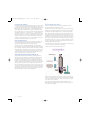
Microporous filter products are used by a number of industries to
achieve required levels of purity in both gases and liquids. The
verification of filter performance has been identified as an important process monitor in several industries, especially in those
applications where product sterilisation or microbial bioburden
reduction is required. This has led to the development of a number of integrity test procedures, based around industry preference
such as in the beverage sector or regulatory definition as in the
pharmaceutical industry.
Validation and product certification
To certify that GE Heathcare products meet the required regulatory and quality standards of the industries we supply, all filters are
supplied with a certificate of conformance. These certificates are
linked to validation guides for both pre-filter and sterilising grade
membrane filter cartridges that define methodologies and data
appropriate to each filter type. This information typically includes:
• technical specifications
Integrity testing offers non-destructive methods for proving the
capability of a filter product to meet its stated performance when
it is installed in an application. This gives confidence to filter users
that both before and after filtration processes the installed filter
will achieve the required performance. In particular, integrity tests
enable users to verify that no filter damage has occurred during
storage, installation into the filter housing or following procedures
such as chemical cleaning or in-situ steam sterilisation prior to
use or during the subsequent manufacturing process.
GE Healthcare - Setting the standard
GE Heathcare bring extensive experience through our scientists,
engineers and sales representatives to the process of offering
specific filtration systems to meet the needs of your production
process. Support services are available covering a wide range of
activities including scale up advice from laboratory through pilot
scale to production systems, validation support, design and manufacturing of custom housings and filtration products and on-site
technical support.
Committed to quality
Quality is of paramount importance to GE Heathcare. As such GE
Heathcare has been certified to ISO 9001 since 1987, providing a
quality management system that covers the entire organisation
from R&D, production, warehousing, materials management and
customer support. In addition, our manufacturing facilities operate to the principles of cGMP.
• biological safety testing including Current USP<88> Class VI 121 °C Plastics
• extractable testing including 21 CFR 211.72 and 210.3(b), (6) for
fibre releasing filters
• effluent quality including TOC, bacterial endotoxins, water conductivity and particle release
• chemical compatibility information
• thermal stability
• correlation of a non destructive integrity test to a defined
bacterial challenge
Where appropriate these data are included in the GE Healthcare
Drug Master File – DMF 7564 at the U.S. Food and Drug
Administration (FDA).
Validation support services
GE Heathcare has extensive laboratory facilities and trained personnel capable of providing a range of validation support services
to support manufacturers meet their requirements for process
validation relating to the use of filtration products.
This commitment is underlined by our registration to ISO 14001
during 2001 and our move to ISO9001:2000.
User Manual
3
GE_UM_NFF IntegTesting_D
1/17/07
11:50 AM
Page 4
The integrity testing principle Establishing correlation to bacterial
challenge data
During the design process for a new filter product, filter manufacturers such as GE Heathcare, validate the filtration performance
to industry defined standards. The Pharmaceutical Industry specifies a sterilising grade filter as one:
rated at 0.22μm or less, capable of producing a sterile filtrate when
challenged with a solution containing sufficient Brevundimonas
diminuta organisms to give a concentration of 107 per cm2 of effective filtration area (EFA).
Prior to bacterial challenge each filter is tested using an appropr
ate non-destructive Integrity Tests.
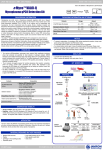
The objective of this ‘correlation’ process is to identify the boundary value, given by the non-destructive test for a filter, below
which filters consistently provide a sterile filtrate following bacterial challenge. Once this boundary value for the non-destructive
integrity test has been identified, it is usual to apply an additional
safety factor in defining the user integrity test limit. GE Heathcare
applies a safety factor, such that the recommended value for the
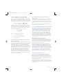
integrity test limit is 75% of the highest value at which a sterile filtrate was obtained during the bacterial challenge. The results of
these tests are usually displayed in a chart similar to the one
shown in figure 1.
This is the only specification that is currently documented in regulatory guidelines, however other filter ratings are assessed similarly using different challenge organisms, for example
• 0.10 μm Acholeplasma laidlawii
• 0.10 μm Acholeplasma laidlawii
• 0.45 μm Serratia marcescens
Filter materials have inherent variation in pore structure and
dependent on the manufacturing process, can be produced at a
range of pore sizes by modification of processing parameters. As
part of the validation process in the development of a membrane
material and subsequently a filter product, a large number of
samples are taken from the manufacturing process and subjected
to bacterial challenge with the organisms identified above. The
process for performing a micro-organism challenge with
Brevundimonas diminuta is defined in two documents. HIMA
(Health Industry Manufacturers Association) now redefined as
AdvaMed (Advanced Medical Technology Association) issued a
guidance document No.3 Vol. 4 Microbiological Evaluation of
Filters for Sterilizing Liquids in April 1992. ASTM (American Society
for Testing and Materials) subsequently issued a standard F83883 Standard Test Method for Determining Bacterial Retention of
Membrane Filters Utilized for Liquid Filtration. Both documents are
referenced by the industry, although ASTM F838-83 is the now
adopted standard method.
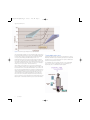
Figure 1. Typical Bacterial Challenge v Integrity Test Value Correlation
Chart
In this example, the boundary integrity test value was 20 (notional
units), below which all filters tested produced a sterile filtrate.
Following the application of an additional safety margin, the user
integrity test limit for this product would be set at 15.
The integrity test methods
Currently there are three main identified Integrity Test Methods
for Liquid Filters, with two additional methods solely for use with
hydrophobic gas filters.
Liquid filter test methods
Bubble Point: the minimum applied differential pressure required
to vent the largest pore in a wetted filter media / membrane
Diffusional Flow: the gas flow rate resulting from gas diffusion
across a wetted filter media at an applied differential pressure of
approximately 80% of the bubble point for that media.
Pressure Decay: the drop in gas pressure measured over time
from a sealed volume connected to the upstream side of a wetted
filter media due to diffusional flow. This is simply another way of
measuring a diffusional flow
4
User Manual
GE_UM_NFF IntegTesting_D
1/17/07
11:50 AM
Page 5
Hydrophobic gas filter test methods
If a differential pressure is now applied using an applied gas pressure on one side of the wetted membrane, two things can happen:
Water Intrusion: the volume of water that penetrates (intrudes)
into the structure of a hydrophobic media at a given applied pressure held for 10 minutes.
The gas can dissolve in the liquid in the pores -
Aerosol Challenge: the concentration of a sub-micron challenge
aerosol that penetrates a filter when challenged at a given
upstream concentration.
(Note: These methods are not covered in this document. For further details see GE Heathcare support document)
Integrity test principles
Gas flow through a wetted filter media
The basic principle used in most methodologies is the measur
ment of a gas flow due to an applied pressure differential through
a fully wetted filter media. This principle is usually applied only to
membrane based filter products. This is because the pore structure and size distribution is normally sub-micron and the mass
flow of gas measured across the membrane through the structure
can be accurately measured with enough sensitivity to differentiate between a ‘good’ and ‘bad’ structure.
Consider a microporous membrane material wetted thoroughly
by a suitable wetting fluid. All the pores are filled with the wetting
liquid and held in the pores by surface tension and associated
capillary forces.
The amount of gas that dissolves is dependent on the solubility of
the gas in the liquid and also the applied pressure. This phenomenon results in a high concentration of dissolved gas at the pressurised side of the membrane, and a low concentration at the
low-pressure side. The gas molecules therefore diffuse across the
pore structure to the low-pressure side due to this concentration
gradient and come out of solution on the low-pressure side. The
resulting transfer of gas is measured as a gas flow is therefore
referred to as diffusional flow.
If pressure is increased high enough the wetting liquid can be
forced from the larger pores The wetting liquid is held in the pores by capillary forces. These
forces are built up due to surface interactions between wetting
liquids and the polymers that make up the membrane. If sufficient
external force is applied, for example, by an applied gas pressure,
then the capillary forces can be overcome and the pores can be
totally emptied of wetting liquid. At this point the surface of the
membrane is seen to bubble, as the escaping gas flows directly
through a shallow pool of the liquid on the downstream side,
hence the term bubble point. The larger the pore the lower the
force required to vent it of liquid. Therefore, theoretically, the first
bubble seen indicates the largest pore in the membrane structure.
User Manual
5
GE_UM_NFF IntegTesting_D
1/17/07
11:50 AM
Page 6
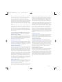
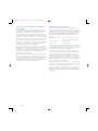
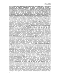
Typical gas flow curve
Figure 2. Gas Flow through a Wetted Microporous Filter Media
The flow through a wetted microporous filter media can therefore
be summarised by three distinct zones. At low applied differential
pressure, the increase in flow rate is almost linear when plotted
on log / log axes with applied differential pressure – the
Diffusional Flow Zone. As the pressure approaches the ‘bubble
point’, the curve turns non-linear as greater numbers of pores are
vented by the applied pressure – the Transitional Flow Zone. Once
all of the pores have been vented, the curve returns to virtually a
linear form on log / log axes – the Mass Flow Zone.
Three simple curves plotted on log / log axes are illustrated in
Figure 2 shows the flows for three different areas of media. It will
be evident from the curves that the distribution of pore size in the
microporous media will determine how short the transitional zone
will be. If the distribution is narrow, then all the pores will vent at
approximately the same applied pressure and the knee in the
curve will be sharp. The wider the distribution, the broader the
knee in the curve. The above principles have led to the development of two distinct test methods based on determining either the
bubble point or the diffusional flow of gas across the membrane.
6
User Manual
The bubble point test
Hydrophilic ("water loving") microporous membranes in contact
with water will fill their pores following principles associated with
capillary forces. To vacate the filled pores requires a differential
pressure to be applied across them.
In a simplified form, the required pressure to vent a liquid filled
pore, P, has an inverse relationship to the pore diameter, d,
described by the so called bubble point equation:
GE_UM_NFF IntegTesting_D
1/17/07
11:50 AM
Page 7
Where _ is the surface tension of wetting fluid, _ is the contact
angle of wetting and K is a pore shape factor constant (since
pores are not simple cylinders in real filter membranes).
In any filter media, there is a distribution of many millions of
pores. As pressure is increased more pores are vented, the largest
ones first. The removal of the wetting liquid from the pores allows
a distinct change in the gas flow through the filter media to be
measured. It is the applied pressure at which this change in gas
flow rate produced that used as the physical indicator or ‘bubble
point’.
The test is carried out by connecting a compressed air supply to
the upstream side of a wetted filter, increasing the applied pressure and then monitoring for a sudden change in gas flow rate.
This procedure can be carried out manually by feeding a pipe
connection from the outlet line through an inverted water filled
glass vessel and simply looking for a constant stream of air bubbles to be visible.
Issues affecting bubble point testing
Operator subjectivity - What does the bubble
point actually measure?
Each operator may have a different protocol that they operate to
in terms of how pressure is applied and what constitutes a constant stream of bubbles. Whilst strictly documented and applied
protocols can lessen the influence, this can be overcome completely by using automated test equipment.
High pressures required
For sterilising grade filters rated at 0.1μm and higher, the bubble
point pressure can be significantly higher than the rated operating pressure of the membrane. The bubble pointing of the product
could end in physical damage of the membrane or in the case of
capsule product, the product housing and seals.
Different wetting fluids
The surface tension of the wetting fluid will affect the bubble point
directly. If a filter has been used to with a specific liquid product,
remnants of that product may be difficult to remove from the filter media, or that product may have a direct effect on the surface
chemistry of the filter media. If any product fluid still remains in
the filter, then once wetted with water this may effect the surface
tension. Also, if there changes in surface chemistry in the filter
media due to contact with the fluid this may change the wetting
angle and hence the bubble point. To overcome these difficulties
and avoid the requirement for prolonged flushing protocols, it
may be prudent to correlate bubble point values in water for a
particular filter to bubble point values in the product fluid to be filtered. The Parenteral Drug Association (PDA) Technical Report No.
26 – Sterilizing Filtration of Liquids published in 1998 gives a protocol to allow this correlation to be produced.
presents an area of approximately 10 cm2 and a 10" cartridge
perhaps 6000 cm2. As the transition zone (indicated in figure 2) is
reached and the flow rate starts to increase, the point at which a
change occurs will vary significantly. For the 47mm disc, in the
region of 0.02 to 0.10 ml/min, and with the 10" cartridge, 8 - 30
ml/min. Assuming that the device used to detect the differences
has a fixed sensitivity for assessing the change in gas flow, be it
the human eye or a physical detector, the change in flow rate in
the larger filter will always be detected before the smaller. To an
observer of the 10-fold air flow increase, it appears much more
like a bubble point at a lower pressure with the larger area than
with the smaller area. Automated machines do much to alleviate
this issue, but it is still a common practice for cartridge bubble
points to be quoted as lower than 47mm disc bubble points.
At the other end of the scale, with multi-round filter assemblies for
example, the difficulty is maintaining sensitivity at much higher
initial flow rates. Consider an 18 round 30" assembly, where even
a significant increase in flow rate for one module may be masked
by the high overall diffusional flow rate from the other 539 x 10"
modules.
Multiple layer filters
Several observers have reported that an increase in thickness of
membrane results in an increase in bubble point values. This can
result in multi-layer products utilising the same grade of final
membrane, having increased bubble points ratings over a single
layer of the same material.
Change in temperature
Temperature changes impact on several physical interaction
parameters. The surface tension of the wetting fluid or the solubility of the test gas in the fluid may change. In cases where a fixed
upstream pressure is applied to the membrane, as for example
with pressure decay testing, change in temperature results in a
corresponding change in pressure. All these effects can produce
significant impacts on the measured bubble point, and therefore
maintenance of a stable temperature is a key to accurate repeatable integrity testing.
Rapid changes in pressure
The procedure to find the bubble point of a particular membrane
based filter requires the pressure to be raised. The rate at which
the pressure is increased can have a dramatic effect on the
measured bubble point. The more rapid the pressure increase the
less time the system has to stabilise and due to lags in the diffusional flow equalisation rate and the sampling system if downstream monitoring is used, the more likely it is to measure a false
high (good) bubble point. Again, standardised protocols and automated test equipment mitigate against this potential source of
error.
Different filter areas
The size of a filter does not effect the intrinsic bubble point of the
material used to construct it. Generally however, a larger area or
filter material will give an indicated bubble point lower than
expected compared to a smaller area.
The reason for this can be seen if we consider the amount of gas
passing through the filter as the media area rises. A 47mm disc
User Manual
7
GE_UM_NFF IntegTesting_D
1/17/07
11:50 AM
Page 8
Procedure for wetting
Most false low bubble point integrity test failures can be put down
to issues associated with achieving full wetting of the pore structure. If the pores of the filter are not completely wetted then a low
bubble point will be measured. The recommended procedure to
ensure wetting is to allow the filter to stand in the wetting solution, typically water, for 5 minutes and then flow the fluid through
the filter at 10 l/min per 10" cartridge for 2 – 3 minutes with an
operating pressure of 1 – 2 bar. In cases where the integrity test
value is still suspect, as a final check, a flush with an alcohol, typically IPA, or hot water can result in full wetting being achieved.
Testing in a wetting solution of 60%: 40% IPA: Water can also be
used where wetting difficulties are encountered.
Filter material issues
The higher the hydrophobicity of the membrane and other constructional materials for the filter, the greater the potential for
variation in bubble point due to incomplete wetting.
Not all filters of the same ratings will exhibit the same bubble
point. This is due to the wetting angle differences with each polymer and liquid combination. Also remember that rating is usually
measured against an ability to remove a specified organism from
a fluid stream, not necessarily the effective pore size. Hence all
0.2Ìm rated products do not have the same bubble point some
observers using terms such as ‘tight’ and ‘open’.
Diffusional flow tests
Diffusional flow based tests operate with applied pressures to
measure gas flows in the diffusional zone.
Gas flow in this zone is produced due to pressure dependent gas
solubility in the wetting liquid and transportation of the dissolved
gas through the wetting liquid due to a concentration gradient.
At the upstream side of a wetted pore, gas dissolves into the surface layer following Henry’s law which states that the amount of
gas dissolved in a liquid is a function of the partial pressure of the
gas above it. As the dissolved gas passes across the pore depth
the pressure drops and the gas re-emerges and is released at the
downstream surface of the pore in accordance with Henry’s Law.
The rate of gas diffusion through the liquid follows Fick’s Law, remodelled by Reti (1977) that states:
Two different physical measurement methods are currently used:
- Pressure Decay / Pressure Hold Measurement
- Diffusional Flow Measurement by Mass Flow
Automated testing algorithm differences
Automated bubble point test equipment supplied by different
manufacturers may determine the bubble point using different
physical parameter measurement e.g. using measurement of
pressure loss or measurement of direct mass flow. Instruments
using the same principle may also potentially use different algorithms to calculate the bubble point e.g. the pressure at which the
flow rate starts to go non- linear compared to the pressure at
which extrapolations of the linear portions of the flow curve intersect. This can result in slight differences in measured bubble point
comparing one manufacturer’s machine to another and variation
depending which method or machine was applied to producing
the initial correlation to bacterial challenge data.
Where N is the permeation rate (number of moles of gas per unit
time), D is the diffusivity of the gas in the liquid, H is the solubility
coefficient of the gas, and L is the depth of the liquid, and _ is the
void volume of the membrane.
This results in the diffusion rate being directly related to the
applied pressure differential and is therefore linear for given values of the other variables.
8
User Manual
GE_UM_NFF IntegTesting_D
1/17/07
11:50 AM
Page 9
Pressure decay / Pressure hold
This, the most commonly adopted method, measures the gas
pressure loss from a pressurised, sealed upstream volume due to
diffusional flow across a membrane filter which is then equated to
a gas flow rate. If the vessel volume is known then the pressure
drop can be related to the loss in gas by the general gas equation:
Diffusional flow measurement by
mass flow
Direct measurement using mass flow transducer technology can
eliminate the requirement for knowing the upstream volume of
the system being tested. Mass Flow sensors can be used to measure the gas flow directly at a constant maintained pressure differential.
lThis technique is currently only limited to a few particular test
instruments and is not yet applied widely.
Gas initially contained in a closed system of known volume V at
pressure P is then left for a set time to diffuse out of the system
through a wetted filter. The change in pressure P then relates
directly to the mass of gas lost through diffusion, and if the time is
known the diffusional flow rate can be calculated.
Where
P1 is the starting pressure in bar
P2 is the finish pressure in bar
V is the sealed upstream volume in ml
t is the time in mins
Diffusional flow measurement from
pressure decay
Indirect measurement of diffusional flow is achieved by including
in the measurement system a method of measuring the upstream
volume. This removes the uncertainty of the Pressure Decay
method, which relies on an accurate volume being already
known. The GE Heathcare PORECHECK 3 incorporates a procedure
for physically measuring the upstream volume. This is achieved
by first filling a vessel of known volume, (located within the instrument), with compressed air or nitrogen gas and then venting it
into the upstream void. The new pressure resulting in the
upstream void added to the defined volume can allow the
upstream volume to be calculated by the use of Boyle’s Law
again, P1V1 = P2V2. A pressure decay test can now be run as normal and the loss in pressure related directly back to a volumetric
flow of gas, the Diffusional Flow.
Issues affecting diffusional flow testing
What does diffusional flow testing actually measure? The diffusional flow test methods assess the effective porosity of a filter
membrane. Any flaw in the membrane will be identified due to an
increase in diffusional flow. Any change in structure not only
associated with the ‘largest’ pore as measured by the bubble
point method will also be identified. As with the bubble point
method however, the numbers obtained from a diffusive flow
measurement only have significance as they are correlated to a
bacterial challenge. The measurement accuracy for diffusive flow
can however be improved compared with bubble point assessments as the subjectivity associated with bubble point measurement is removed.
Measurements of high area filters
As shown above, increases in the area of a filter membrane in a
product can give problems with the identification of the bubble
point, as the impact of the high levels of diffusional flow blur the
transition point. Most manufacturers will recommend the use of
diffusional flow for larger filter systems.
Requirement to know the upstream volume
The most common method to assess diffusional flow for a membrane filter uses a pressure decay methodology as previously
described. This requires the upstream volume to be known accurately. GE Heathcare supplies details of it’s own housing volumes
when GE Heathcare filter products are being used. In cases where
alternative suppliers have supplied the housings, this data may
not be readily available. Current integrity test instruments incorporate this measurement capability as part of the testing protocol.
Selection of integrity test
GE Heathcare recommends that the diffusional flow test be
applied to most products in capsule and cartridge format.
Diffusional flow testing is simple to perform using automated test
instruments such as the PORECHECK Integrity Tester, and avoids
some difficulties in maintaining repeatability which is associated
with the bubble point method.
In cases where the filter media area is small, i.e. discs, there is no
real alternative to bubble point testing as the diffusional flow rates
are so small that the sensitivity of the automated instruments do
not allow their use.
User Manual
9
GE_UM_NFF IntegTesting_D
1/17/07
11:50 AM
Page 10
Integrity test methods - Procedures
Wetting the filter on test
When to test
If the steaming of the filter or other processing issues prevent
wetting in process fluids as above, then it may be required to wet
the filter with water before integrity testing. This will normally be
achieved using the appropriate grade of pharmaceutical water
used in the process, often Water for Injection (WFI). To ensure that
the products are fully wetted, the GE Heathcare guideline for
flushing is:
The EU cGMP Guidelines resulting from the 2001/83/EC and
2001/82/EC Directives for Human and Veterinary Drug Products
state in Annex 1 Manufacture of Sterile Medicinal Products: "The integrity of the sterilised filter should be verified before use
and should be confirmed immediately after use by an appropriate
method such as bubble point, diffusion flow or pressure hold test."
If steaming protocols are in place, then the ideal is to test post initial sterilisation, perhaps in the first product filtered and subsequently immediately post filtration, again in the process fluid. GE
Heathcare can provide a service to identify the appropriate
integrity test value for process wetting fluids.
The US cGMP guidelines are documented in the Code of Federal
Regulations. There are no specifics identified here, however, in the
CDER Guidance for Industry (1997) the Guideline on Sterile Drug
Products Produced by Aseptic Processing (June 1987) is reviewed
where reference is made to integrity testing under section
Sterilization Operations, Filtration:
Normally, integrity testing of the filter is performed after the filter
unit is assembled and sterilised prior to use. More importantly,
however, such testing should be conducted after the filter is used in
order to detect any filter leaks or perforations that may have
occurred during the filtration. "Forward Flow", "bubble point" and
"pressure hold" tests are acceptable integrity tests.
Cartridges / Capsules:
Flush for 3 minutes at 15 to 20 litres
per min per 10" (250mm) module
Discs: 47mm - 10ml
90mm - 50ml
142mm - 100ml
293mm - 500ml
It is very important to ensure that the pore structure for the filter
to be tested has been fully wetted. Any trapped gas in the filter or
hydrophobic areas will distort the final reading significantly leading to the potential of false fails being registered.
It is important to note that after processing some fluids, the
traces of product can be difficult to remove. Often the fluid can
introduce some hydrophobicity into the filter products, which
results in false fails in integrity testing. Under these circumstances
appropriate procedures must be considered such as hot water
flushing or flushing with mild compatible solvents. An alternative
approach can also be considered using a better wetting solution
such as ISO Propyl Alcohol / Water mixes.
Another increasingly common approach is to consider testing in
the product itself, with Integrity Test values derived and validated
by GE Heathcare Technical Support Group (TSG).
Dip wetting (simply submerging a filter product in liquid) has been
used successfully on occasion, but is not a recommended procedure and must be validated by the user into standard operating
procedures.
10
User Manual
GE_UM_NFF IntegTesting_D
1/17/07
11:50 AM
Page 11
Technical support group activities
GE Heathcare have a trained team of scientists and engineers
available to answer questions regarding the technical capabilities
of our products, to assist in the selection and design of appropriate filtration systems and to provide user training programs. The
following services can be delivered both on site and in-house;
• filterability testing to optimise filter system design
• advice on the development of integrity testing, steam sterilisation and clean in place procedures
• development of validation procedures
• troubleshooting
• facility audits to ensure continued optimisation of filter use
• operator training including filtration theory, filter system design
and management, validation, etc.
For more information on any of the above support services please
contact your local GE Heathcare representative.
website: www.GEHealthcare.com/filtration
User Manual
11
GE_UM_NFF IntegTesting_D
1/17/07
11:50 AM
Page 12
www.gehealthcare.com/filtration
GE, imagination at work and GE monogram are trademarks of
General Electric Company.
GE Healthcare Bio-Sciences AB
Björkgatan 30, 751 84 Uppsala, Sweden
All goods and services are sold subject to the terms and conditions
of sale of the company within GE Healthcare which supplies them.
A copy of these terms and conditions is available on request.
Contact your local GE Healthcare representative for the most current information.
© 2007 General Electric Company - All rights reserved.
GE Healthcare Bio-Sciences AB, a General Electric Company.
GE Healthcare Europe GmbH
Munzinger Strasse 5, D-79111 Freiburg, Germany
GE Healthcare UK Ltd
Amersham Place, Little Chalfont, Buckinghamshire, HP7 9NA, UK
GE Healthcare Bio-Sciences Corp
800 Centennial Avenue, P.O. Box 1327
Piscataway, NJ 08855-1327, USA
GE Healthcare Bio-Sciences KK
Sanken Bldg. 3-25-1, Hyakunincho, Shinjuku-ku,
Tokyo 169-0073, Japan
Asia Pacific Tel +65 6275 1830 Fax +65 6275 1829 Australasia Tel + 61 2 9899 0999 Fax +61 2 9899 7511 Austria Tel 01/57606-1619 Fax 01/57606-1627 Belgium Tel 0800 73 888 Fax 02 416 82 06 Canada Tel 800 463 5800 Fax 800 567 1008
Central, East, & South East Europe Tel +43 1 972720 Fax +43 1 97272 2750 Denmark Tel 45 16 2400 Fax 45 16 2424 Finland & Baltics Tel +358 (0)9 512 39 40 Fax +358 (0)9 512 39 439 France Tel 01 69 35 67 00 Fax 01 69 41 96 77
Germany Tel 089 96281 660 Fax 089 96281 620 Greater China Tel +852 2100 6300 Fax +852 2100 6338 Italy Tel 02 27322 1 Fax 02 27302 212 Japan Tel +81 3 5331 9336 Fax +81 3 5331 9370 Latin America Tel +55 11 3933 7300 Fax +55 11 3933 7304
Middle East & Africa Tel +30 210 9600 687 Fax +30 210 9600 693 Netherlands Tel 0800 82 82 82 1 Fax 0800 82 82 82 4 Norway Tel 815 65 555 Fax 815 65 666 Portugal Tel 21 417 7035 Fax 21 417 3184 Russia & other C.I.S. & N.I.S Tel +7 (495) 956 5177
Fax +7 (495) 956 5176 Spain Tel 93 594 49 50 Fax 93 594 49 55 Sweden Tel 018 612 1900 Fax 018 612 1910 Switzerland Tel 0848 8028 12 Fax 0848 8028 13 UK Tel 0800 616928 Fax 0800 616927 USA Tel 800 526 3593 Fax 877 295 8102
28-9137-76 AA 01/2007