1
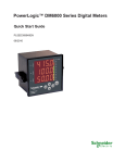
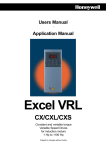
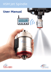
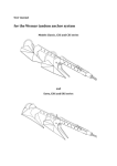
VACON
CX/CXL/CXS
FREQUENCY CONVERTERS
7-segment
Control Panel
Subject to changes without notice.
FOR SMOOTH CONTROL
VACON 7-SEGMENT CONTROL PANEL
INDEX
Page
1. General ................................................................ 2
2. Panel operation .................................................... 3
3. Monitoring page .................................................... 4
4. Parameter page ................................................... 6
5. Reference page ................................................... 6
6. Programmable push-button page ........................ 7
7. Fault history page ................................................ 8
8. Active fault display ............................................... 8
9. Active warning display .......................................... 9
10. Controlling the motor from the front panel .......... 10
10.1 Control source change from I/O terminal
to front panel .............................................. 10
10.2 Control source change from control panel
to I/O terminal ............................................ 10
Page 2 (10)
1.
7-segment Control panel
Vacon
GENERAL
The 7-segment control panel of the Vacon
frequency converter has a six-digit LED display,
three drive status indicators, four active menu
page indicators and eight push-buttons.
The panel is removable and it has full galvanic
isolation from the mains potential. The same
panel can be used with all Vacon frequency
converters.
In other questions and problems with Vacon
CX/CXL/CXS frequency converter, please refer
to the CX/CXLCXS User's Manual or the Five
In One+ Application Manual
DRIVE STATUS INDICATORS
RUN
MON
READY
PAR
REF
FAULT
RUN =
lights when the motor is
running
READY =
lights when mains voltage has
been applied and the drive is
ready to operate
FAULT =
lights if fault occurs
DISPLAY
Displays parameter values,
monitoring data, etc., six digits
BTNS
ACTIVE MENU PAGE INDICATORS
RST
PG
UD008K17
BTNS
=
Programmable push-button
(menu page)
REF
page)
=
Reference
PAR
=
Parameters (menu page)
MON
=
Monitoring values (menu page)
(none)
=
Fault history (menu page)
values
(menu
Figure 1. Control panel with LED display.
PUSH-BUTTONS
= Tab button:
Toggles between display item indication
and item data
RST
PG
= Arrow up/down buttons:
Changes item or data value
= Enter button:
Confirms the parameter value setting.
Acts as push-button on the
programmable push-button page.
On the PAR-page the parameter
number on the display will be changed
into a higher parameter group.
Vacon Plc
Phone: +358-(0)201 2121
Service: +358-(0)40-8371 150
= Reset button:
Resets faults
= Page button:
Changes active menu page
= Start button:
Starts the motor if the panel is the
active control source
= Stop button:
Stops the motor if the panel is the
active control source
Fax:
+358-(0)201 212 205
E-mail: [email protected]
7-segment Control panel
Vacon
2.
Page 3 (10)
Panel Operation
The panel operation is clear and it is organised
in page type menus. There are different menu
pages for monitoring, parameter settings,
references, programmable push-button
functions and fault history.
The active menu page LED as well as the
leftmost character in the six digit read-out
indicate which one of the pages is active. See
the panel menu chart below.
RUN
RUN
RUN
RUN
READY
MON
MON
MON
Monitoring page
MON
READY
READY
READY
FAULT
PAR
PAR
PAR
PAR
FAULT
FAULT
FAULT
REF
REF
REF
REF
RUN
READY
FAULT
BTNS
BTNS
BTNS
MON
BTNS
PAR
REF
BTNS
PG
RUN
RUN
RUN
RUN
MON
MON
MON
Parameter page
MON
READY
READY
READY
READY
PAR
PAR
PAR
PAR
FAULT
FAULT
FAULT
FAULT
REF
BTNS
REF
BTNS
REF
BTNS
REF
RUN
BTNS
MON
READY
PAR
FAULT
REF
BTNS
PG
RUN
READY
FAULT
RUN
BTNS
MON
READY
FAULT
Reference page
MON
PAR
REF
PAR
REF
PG
RUN
RUN
RUN
Programmable
push-button page
MON
MON
MON
READY
READY
READY
PAR
PAR
PAR
FAULT
FAULT
FAULT
REF
REF
BTNS
BTNS
REF
BTNS
PG
RUN
RUN
RUN
Fault page
MON
MON
MON
READY
READY
FAULT
FAULT
READY
FAULT
PAR
PAR
REF
REF
PAR
REF
BTNS
BTNS
BTNS
PG
Figure 2. Panel operation.
Vacon Plc
Phone: +358-(0)201 2121
Service: +358-(0)40-8371 150
Fax:
+358-(0)201 212 205
E-mail: [email protected]
BTNS
Page 4 (10)
7-segment Control panel
Vacon
7.3 Monitoring page
data values can be selected for display with the
tab push-button.
The MON indicator is lit when the monitoring
page is active. In the item display the symbol
for monitoring is "n" and the next digit is the
item number. Figure 3. shows how monitored
RUN
MON
READY
PAR
RUN
REF
READY
Table 1. lists all the possible monitored items.
All values are updated every 200 ms.
FAULT
RUN
BTNS
MON
PAR
PAR
REF
FAULT
BTNS
FAULT
PG
MON
READY
REF
Next page
BTNS
Figure 3. Monitoring page.
Number
Data name
Unit
n1
Output frequency
Hz
Frequency to the motor
n2
Motor speed
rpm
Calculated motor speed
n3
Motor current
A
Measured motor current
n4
Motor torque
%
Calculated actual torque/nominal torque of the unit
n5
Motor power
%
Calculated actual power/nominal power of the unit
n6
Motor voltage
V
Calculated motor voltage
n7
DC-link voltage
V
Measured DC-link voltage
n8
Temperature
°C
Temperature of the heat sink
n9
Operating day counter
DD.dd
Operating days 1), not resettable
n 10
Operating hours, "trip
counter"
HH.hh
Operating hours 2), can be reset with programmable button #3
n 11
MW-hours
MWh
Total MW-hours, not resetable
n 12
MW-hours, "trip
counter"
MWh
MW-hours, can be reset with programmable
button #4
n 13
Voltage/analogue input
V
n 14
Current/analogue input
mA
n 15
Digital input status, gr. A
See Figure 4.
n 16
Digital input status, gr. B
See Figure 5.
n 17
Digital and relay output
status
See Figure 6.
n 18
Control program
Version number of the control software
n 19
Unit nominal power
n 20
Motor temperature rise
kW
%
Table 1. Monitored items.
Description
Voltage of the terminal Uin+ (term. #2)
Current of terminals Iin+ and Iin- (term. #4, #5)
Shows the power size of the unit
100%= temperature of motor has risen to nominal value
1)
2)
Vacon Plc
Phone: +358-(0)201 2121
Service: +358-(0)40-8371 150
DD = full days, dd = decimal part of a day
HH = full hours, hh = decimal part of an hour
Fax:
+358-(0)201 212 205
E-mail: [email protected]
7-segment Control panel
Vacon
Page 5 (10)
Digital input
Status indication
RUN
READY
FAULT
RUN
READY
FAULT
0 = open input
1 = closed input (active)
MON
PAR
REF
BTNS
MON
PAR
REF
BTNS
Example:
Input
DIA1
closed
8
DIA2
closed
9
DIA3
open
Figure 4.
RUN
MON
READY
PAR
Figure 5.
MON
10
Digital inputs, Group A status.
REF
FAULT
RUN
BTNS
MON
READY
PAR
FAULT
REF
BTNS
7
Example:
Input
RUN
Terminal
Terminal
DIB4
closed
14
DIB5
open
15
DIB6
closed
16
Digital inputs, Group B status.
READY
PAR
REF
FAULT
RUN
BTNS
MON
READY
PAR
FAULT
REF
BTNS
Example:
Output
Terminal
Digital output
20
closed (sinking current)
Figure 6.
Vacon Plc
Relay output 1
open
21
Relay output 2
open
24
Output signal status.
Phone: +358-(0)201 2121
Service: +358-(0)40-8371 150
Fax:
+358-(0)201 212 205
E-mail: [email protected]
Page 6 (10)
4.
7-segment Control panel
Vacon
Parameter page
The PAR indicator is lit when the Parameter
page is active. Figure 7. shows how the
parameter values can be changed.
The enter button
confirms the change of
the parameter value. When the new value is
confirmed the PAR indicator blinks once.
If the enter button is not pressed the parameter
value will not be changed.
In the Basic application (default setting) there
is only parameter Group 1 which has all
RUN
Parameter
page
READY
FAULT
necessary parameters for the basic use of the
device and System parameter Group 0. Group
0 becomes visible only when the Application
package lock is opened. See Vacon CX/CXL/
CXS User's Manual Chapter 11.
Other applications have more parameter
groups. Parameters of the groups follow each
other and changing from the last parameter of
one group to the first parameter of the next
group or vice versa is done simply by pushing
arrow up/arrow down buttons. Alternatively,
pressing
selects the next group.
RUN
READY
FAULT
Increment value
Decrement value
Parameter
group
MON
PAR
RUN
REF
READY
BTNS
MON
PAR
REF
BTNS
Confirm value
FAULT
Parameter
number
PG
Next page
Parameter value
MON
PAR
REF
BTNS
Figure 7. Parameter page.
5.
Reference page
The reference page is active when the REF
indicator is lit.
If the Control panel is the active control source,
the frequency reference can be changed by
changing the value on the display with arrow
up/arrow down push-buttons, see Figure 8.
RUN
READY
FAULT
RUN
The reference change is valid immediately. The
motor speed changes as fast as the reference
is changing or the load inertia allows the motor
to accelerate/decelerate.
The active control source can be selected with
programmable button 2, see Chapter 6.
READY
FAULT
Increment
reference value
Reference
page
Decrement
reference value
MON
PAR
REF
PG
RUN
MON
Next page
READY
PAR
MON
BTNS
PG
PAR
REF
BTNS
Reference value
FAULT
REF
BTNS
Figure 8. Control panel reference value setting.
Vacon Plc
Phone: +358-(0)201 2121
Service: +358-(0)40-8371 150
Fax:
+358-(0)201 212 205
E-mail: [email protected]
7-segment Control panel
Vacon
6.
Page 7 (10)
Programmable push-button page
The BTNS indicator is lit when the
programmable push button page is active. The
function of the enter button can be selected on
this page. The selected function is valid only
on this page and on other pages the enter
button has it’s original function. The feedback
information tells the state of the button
function. When the button is pressed, the
feedback information is shown small.
Push down
RUN
READY
RUN
FAULT
READY
FAULT
Button-page
Button no.
MON
RUN
MON
RUN
PAR
REF
READY
PAR
BTNS
Feedback
information
FAULT
REF
READY
MON
RUN
BTNS
FAULT
The feedback information
is shown small when the
button is pushed
MON
PAR
REF
READY
PAR
BTNS
FAULT
REF
BTNS
The feedback information
changes its state as soon
as "push down" has been
recognized
Release
The feedback information
is shown big when
the button is released
MON
PAR
REF
BTNS
Figure 9. Programmable push button page.
Button
number
Button
name
Function
Feedback information
0
1
Note
b1
Reverse
Changes the direction
of rotation of the motor .
Active only if the panel is
the active control source
Direction
command
forward
Direction
command
reverse
b2
Active
control
source
Selects the active control
source between the
panel and I/O terminals
Control via
I/O terminals
Control from the
Control Panel
b3
Clear trip
operating
hour
counter
When pressed clears
the trip operating hour
counter
No clearing
Clearing accepted
b4
Clear trip
MWh
counter
When pressed clears
the MWh trip counter
No clearing
Clearing accepted
Feedback information
flashes as long as
direction is different
from the command
Table 2. Programmable push-buttons.
Vacon Plc
Phone: +358-(0)201 2121
Service: +358-(0)40-8371 150
Fax:
+358-(0)201 212 205
E-mail: [email protected]
Page 8 (10)
7.
7-segment Control panel
Vacon
Fault history page
has always number 1, the previous 2 and so
on. If 9 faults are in the memory, the next
coming fault erases the oldest fault record from
the memory.
When none of the indicators is lit, the fault
history page is active, see Figure 10. The
Vacon frequency converter stores maximum
9 faults in the order they appear. The latest fault
Fault code
RUN
READY
Clears the whole
fault history, push
until "FI " goes to "0 "
FAULT
PG
PG
MON
PAR
Fault page code
REF
Next fault record
BTNS
Fault number
Previous fault record
Figure 10. Fault history page.
8. Active fault display
When a fault trip occurs, the fault indicator is
lit and the blinking symbol F appears on the
display together with a blinking fault code. The
fault codes are explained in Chapter 9 of the
Vacon CX/CXLCXS User's Manual.
display it had before the trip.
The display can be cleared with the Page
button (PG). The read-out returns to the same
Note! Remove external Start signal before
resetting a fault.
RUN
MON
RUN
READY
PAR
The fault remains active until it is cleared with
the Reset button (RST) or with the reset
signal from the I/O terminal.
See figure 11.
FAULT
REF
READY
If multiple fault trips occur
at the same time, the other fault codes can be
checked with arrow up/
down buttons
BTNS
RUN
FAULT
READY
FAULT
PG
MON
PAR
REF
BTNS
MON
RST
RUN
MON
READY
PAR
REF
PAR
REF
BTNS
Fault code
blinks
FAULT
RST
BTNS
Figure 11. Active fault display.
Vacon Plc
Phone: +358-(0)201 2121
Service: +358-(0)40-8371 150
Fax:
+358-(0)201 212 205
E-mail: [email protected]
7-segment Control panel
Vacon
9.
Page 9 (10)
Active warning display
When a warning occurs a symbol "A " appears
on the display together with a blinking warning
code. See Figure 12. Warning codes are
explained in Table 3.
button and the display returns to the state
before the warning* appeared. If the cause of
the warning stays active, a new warning is not
given for 1 minute.
The display can be cleared with the PG (Page)
* The warning will be automatically cleared after 1
minute.
Warning codes:
Code
Warning
Checking
A 15
Motor stalled (Motor stall protection)
Check motor
A 16
Motor over temperature (Motor thermal protection)
Decrease motor loading
A 17
Motor underload
(Warning can be activated in "Five in One" applications)
Check motor loading
A 24
The values in the Fault history, MWh-counters or
operating day/hour counters might have been
changed in a previous mains interruption.
Does not need any actions
Take a critical attitude to these
values
A 28
The change of an application has failed
Choose the application again and
Push Enter-button
A 30
Onbalance current fault, the load of the segments is
not equal.
Contact nearest Vacon distributor
A 45
Vacon frequency converter overtemperature warning,
temperature >70°C
Check the cooling air flow and
the ambient temperature
A 46
Reference warning, the current of input Iin+ <4 mA
Check the current loop
(Warning can be activated in "Five in One" applications) circuitry
A 47
External warning
Check the external fault circuit or
(Warning can be activated in "Five in One" applications) device
Table 3. Warning codes.
RUN
MON
READY
PAR
REF
FAULT
BTNS
RUN
MON
PG
RUN
MON
READY
PAR
REF
READY
PAR
REF
FAULT
BTNS
Warning
code blinks
FAULT
BTNS
Figure 12. Warning code display.
Vacon Plc
Phone: +358-(0)201 2121
Service: +358-(0)40-8371 150
Fax:
+358-(0)201 212 205
E-mail: [email protected]
Page 10 (10)
7-segment Control panel
Vacon
10. Controlling the motor from the front
panel
10.2
Vacon CX/CXL/CXS can have controls from
the I/O terminals or from the front panel. The
active control source can be changed with the
programmable push button b2 (see Chapter
6.). The motor can be started, stopped and
direction of rotation can be changed from the
active control source.
After changing the control source, the I/O
terminals determine the run-state, direction of
rotation and reference value.
10.1 Control source change from I/O
terminals to front panel
After changing the control source the motor is
stopped. The direction of rotation remains the
same as with I/O control.
Control source change from panel
to I/O terminals
If motor potentiometer is used in the
application, the panel reference value can be
copied for a value of motor potentiometer
reference by pushing the start button at the
same time as the programmable push button
b2. Motor potentiometer function mode must
be "resetting at stop state" (Local/Remote
Application: param. 1. 5 =4, Multi-purpose
Application : param. 1. 5 = 9).
If the Start button is pushed at the same time
as the programmable push button b2, the Runstate, direction of rotation and reference value
will be copied from the I/O terminals to the front
panel.
Vacon Plc
Phone: +358-(0)201 2121
Service: +358-(0)40-8371 150
Fax:
+358-(0)201 212 205
E-mail: [email protected]
ud00351b.p65
13.10.2000
Vacon Plc
P.O.Box 25
Runsorintie 7
65381 VAASA
Tel. +358-(0)201-2121
Fax. +358-(0)201-212 205
On-call: +358-(0)40-8371 150
E-mail: [email protected]
http://www.vacon.com