1
swru138
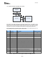
Pins
Function
Description
Default mounted
1-2
JOY_MOVE
See P1, 37-38
Yes
3-4
JOY_LEVEL
See P1, 35-36
Yes
5-6
LCD_FLASH_RESET
See P1, 33-34
Yes
7-8
LCD_MODE
See P1, 31-32
Yes
9-10
LCD_CS
See P1, 29-30
Yes
11-12
MISO
See P1, 27-28. Connected to LCD and serial Flash.
Yes
13-14
MOSI
See P1, 25-26. Connected to LCD and serial Flash.
Yes
15-16
SCLK
See P1, 23-24. Connected to LCD and serial Flash.
Yes
17-18
FLASH_CS
Chip select for serial flash
Yes
19-20
BUTTON1
Button 1. Low when pushed.
Yes
21-22
BUTTON2
Button 2. Low when pushed.
Yes
23-24
LED1
Control signal for LED D1. Set high to turn LED on.
Yes
25-26
LED2
Control signal for LED D2. Set high to turn LED on.
Yes
27-28
LED3
Control signal for LED D3. Set high to turn LED on.
Yes
29-30
LED4
Control signal for LED D4. Set high to turn LED on.
Yes
31-32
JOYSTICK_UP
Signal goes high when joystick is moved up.
Yes
33-34
JOYSTICK_DN
Signal goes high when joystick is moved down.
Yes
35-36
JOYSTICK_LT
Signal goes high when joystick is moved left.
Yes
37-38
JOYSTICK_RT
Signal goes high when joystick is moved right.
Yes
39-40
JOYSTICK_PUSH
Signal goes high when joystick is pushed.
Yes
41-42
POT_R
Voltage level from potentiometer. Value between 0 and VCC.
Yes
EM_RESET
Reset signal to EM. Set either by the USB controller or as a
result of pushing the EM reset button.
Yes
43-44
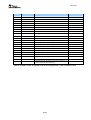
Table 6 - Jumpers on P4. IO signals from all of the peripherals on the evaluation board.
26/33