1
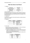
Color Sensor User Manual
Waveshare
Color Sensor User Manual
1. Features
Sensing chip
Identification type
Dimensions
Fixing hole size
Best detecting distance
TCS3200 (full color detector)
Static identification
36.0mm*20.5mm
2.0mm
10mm
Table 1: Product features
Operating principle:
The functional block diagram of TCS3200D is shown in the figure below.
TCS3200D contains four types of filters: red filter, green filter, blue filter
and clear with no filter. When the sensor is illuminated by a ray of light, the
types of filters (blue, green, red, or clear) used by the device can be
selected by two logic inputs, S2 and S3. Table 2 illustrates the relationship
among S2, S3 and filter type.
S2
S3
Filter type
L
L
H
H
L
H
L
H
Red
Blue
Clear (no filter)
Green
Table 2: Relationship among S2, S3 and filter type
TCS3200D outputs a square wave (50% duty cycle) with frequency
corresponding to light intensity and color, and the frequency is directly
proportional to light intensity. The typical output frequency of TCS3200D is
in a range of 2Hz to 500KHz. User can control frequency values of 100%,
20%, and 2% by two programmable outputs, S0 and S1, as Table 3 shown.
1
Color Sensor User Manual
Waveshare
S0
S1
Output Frequency Scaling
L
L
H
H
L
H
L
H
Power down
2%
20%
100%
Table 3: Relationship among S0, S1 and output frequency scaling
TCS3200D has different sensitivities to red, green and blue. As a result,
the RGB output of pure white is not always 255. Therefore, white balance
adjustment is required after power up within 2 seconds. Here are the
processes.
① Place a white paper at the top of the sensor in a distance of 1cm, and
input a High level voltage to LED port to light up 4 bright white LED
indicators.
② The program selects R, G and B filters respectively, and measures the
corresponding RGB values of red, green and blue.
③ Calculate 3 adjustment parameters corresponding to red, green and
blue respectively, and perform automatic white balance adjustment.
2. Applications
This module can be applied to color sorting, environmental light induction
and calibration, test strip reading, color matching test, etc.
3. Interfaces
Pin No.
Symbol
Descriptions
1
2
LED
OUT
3
S3
4
S2
5
S1
6
S0
7
8
GND
VCC
Control the states of 4 LED indicators
Read the output frequency of RGB
Combined with S2, select filters for different
color lights
Combined with S3, select filters for different
color lights
Combined with S0, select output frequency
scaling
Combined with S1, select output frequency
scaling
Power ground
Positive power supply (2.7V-5.5V)
Table 4: Interface specifications
2
Color Sensor User Manual
Waveshare
4. How to use
We will illustrate the usage of the module with an example of color
identification by connecting a development board.
① Download relative codes to the development board.
The configuration of the connection between the module and the
development board are shown in Table 5 and Table 6.
Port
STM32 MCU pin
LED
OUT
S3
S2
S1
S0
GND
VCC
3.3V
GPIOA.0
GPIOA.4
GPIOA.3
NC
NC
GND
3.3V
Table 5: Connection between STM32 development
board and the module
Port
Arduino pin
LED
OUT
S3
S2
S1
S0
GND
VCC
3.3V
D2
D3
D4
D5
D6
GND
5V
Table 6: Connection between Arduino and the
module
The configuration of the serial port is listed in Table 7.
Baud rate
115200
Data bits
8
Stop bit
1
Parity bit
None
Table 7: Serial port configuration
② Place a white paper at the top of the sensor in a distance of 1cm.
③ Power up the development board, and input a High level to LED port to
light up 4 bright white LED indicators.
3
Color Sensor User Manual
Waveshare
④ Wait for 2 seconds or more after power up (automatic white adjustment
is conducted during this period).
⑤ After the adjustment completed, place an objective to be measured at
the front side of the sensor. Then, you can see relative data of RGB are
outputted. A color check list is helpful for finding out what the measured
color it is.
5. Considerations
① Light interference from outside should be avoided, which may affect
the result of color identification. It is recommended to place the light
source and Color Sensor in a close, light reflection free box for testing.
② White balance adjustment is required whenever Color Sensor module
is reset or light source is changed.
4