1
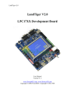
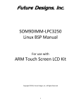
www.waveshare.com Open407I-C & Open207I-C User Manual Open407I-C & Open207I-C User Manual Contents Preparation ................................................................................................................................................................................. 3 ADC+DMA ................................................................................................................................................................................. 3 CAN1 TO CAN2-Normal .......................................................................................................................................................... 4 DAC ............................................................................................................................................................................................. 5 DCMI_OV7670 .......................................................................................................................................................................... 6 DCMI_OV9655 .......................................................................................................................................................................... 7 DS18B20 ...................................................................................................................................................................................... 8 GPIO_Key_LED ........................................................................................................................................................................ 9 I2C ............................................................................................................................................................................................. 10 LCD-HY32D_FSMC ................................................................................................................................................................11 MCO_OUT ............................................................................................................................................................................... 12 Nand Flash_PCB0 .................................................................................................................................................................... 12 Nand Flash_SCB0 .................................................................................................................................................................... 13 NorFlash.................................................................................................................................................................................... 13 PS2 ............................................................................................................................................................................................. 14 RTC ........................................................................................................................................................................................... 15 SD_FatFS .................................................................................................................................................................................. 16 SDIO .......................................................................................................................................................................................... 17 SPI ............................................................................................................................................................................................. 18 SRAM ........................................................................................................................................................................................ 18 TouchPanel ............................................................................................................................................................................... 19 UcosII2.91+UCGUI3.90A ....................................................................................................................................................... 20 USARTx_pritf .......................................................................................................................................................................... 20 1 www.waveshare.com Open407I-C\Open207I-C Testing Guide VS1003B MP3 Board............................................................................................................................................................... 21 I2S .............................................................................................................................................................................................. 22 USB FS Example ...................................................................................................................................................................... 23 USB HS Example ..................................................................................................................................................................... 27 ETH ........................................................................................................................................................................................... 33 2 www.waveshare.com Open407I-C\Open207I-C Testing Guide Preparation Basic settings of the test ·Programming Interface: SWD ·Serial port settings: Select a proper COM port, configure as follows: Baud rate: 115200; Data bits: 8; Stop bits : 1; Parity bits : None; Flow control : None ·Power supply: 5V power supply is required. ·Hardware Connection: For the tests that require the serial port converter for debugging, please connect the converter to the board via pin headers, and then connect it to the PC via USB cable; and open the two jumpers PA9 and VBUS. As shown in the figure below: ADC+DMA Overview ADC analog voltage acquisition ADC Hardware Connection 3 www.waveshare.com Open407I-C\Open207I-C Testing Guide ·Connect the serial port converter to the board via UART1 interface. ·Connect the Analog Test Board to the board via SPI1 interface. As shown in the figure below: Operation and Result Launch the serial debugging assistant, and configure it as described in chapter "Preparation". Info/message will be displayed on the serial debugging assistant as adjusting the resistor on the module. CAN1 TO CAN2-Normal Overview CAN1 TO CAN2-Normal demo Hardware Connection ·Connect the serial port converter to the board via UART1 interface. ·Two "SN65HVD230 CAN Board" are required for this test. ·Connect the two "CAN Board" to the board CAN1, CAN2 interface respectively. ·Connect the two "CAN Board" by using jumper wires (CANH <-> CANH, CANL <-> CANL). As shown in the figure below: 4 www.waveshare.com Open407I-C\Open207I-C Testing Guide Operation and Result Launch the serial debugging assistant, and configure it as described in chapter "Preparation". Press USER key and check the results on the serial debugging assistant. DAC Overview DAC output demo Hardware Connection ·Connect the Analog Test Board to the board via SPI1 interface. ·Connect the 5V pin headers on both the main board and the Analog Test Board via jumper wire. As shown in the figure below: 5 www.waveshare.com Open407I-C\Open207I-C Testing Guide Operation and Result There will be a sound of triangular wave from the Analog Test Board. DCMI_OV7670 Overview OV7670 Digital camera data acquisition and display on the LCD Hardware Connection ·Connect the OV7670 Camera Board to the board via DCMI interface. ·Connect the serial port converter to the board via UART1 interface. ·Connect the 3.2inch 320x240 Touch LCD (A) to the board via LCD interface. As shown in the figure below: 6 www.waveshare.com Open407I-C\Open207I-C Testing Guide Operation and Result Images acquired from the camera will be displayed on the LCD. DCMI_OV9655 Overview OV9655 Digital camera data acquisition and display on the LCD Hardware Connection ·Connect the OV9655 Camera Board to the board via DCMI interface. ·Connect the serial port converter to the board via UART1 interface. ·Connect the 3.2inch 320x240 Touch LCD (A) to the board via LCD interface. As shown in the figure below: 7 www.waveshare.com Open407I-C\Open207I-C Testing Guide Operation and Result Images acquired from the camera will be displayed on the LCD. DS18B20 Overview DS18B20 temperature measurement demo Hardware Connection ·Insert the DS18B20+ to the ONE-WIRE Interface. ·Connect the serial port converter to the board via UART1. As shown in the figure below: 8 www.waveshare.com Open407I-C\Open207I-C Testing Guide Operation and Result Launch the serial debugging assistant, and configure it as described in chapter "Preparation". Info/message will be displayed on the serial debugging assistant. GPIO_Key_LED Overview LED, push button, joystick demo Hardware Connection ·Short the LED jumpers on the board. ·Short the push button and joystick jumper on the board. As shown in the figure below: 9 www.waveshare.com Open407I-C\Open207I-C Testing Guide Operation and Result Push the button or joystick; the LED status will keep changing accordingly. I2C Overview I2C EEPROM demo Hardware Connection ·Connect the serial port converter to the board via UART1 interface. ·Connect the AT24CXX EEPROM Board to the board via I2Cx interface (I2C1 or I2C2, depending on the software configuration). As shown in the figure below: 10 www.waveshare.com Open407I-C\Open207I-C Testing Guide Operation and Result Launch the serial debugging assistant, and configure it as described in chapter "Preparation". Info/message will be displayed on the serial debugging assistant. LCD-HY32D_FSMC Overview LCD display demo Hardware Connection ·Connect the 3.2inch 320x240 Touch LCD (A) to the board via LCD Interface. As shown in the figure below: Operation and Result Information will be displayed on the LCD. 11 www.waveshare.com Open407I-C\Open207I-C Testing Guide MCO_OUT Overview Clock signal output demo Operation and Result Output 8MHz external crystal signal on the MCO0 (PA8 pin) Nand Flash_PCB0 Overview NAND FLASH demo Hardware Connection ·Connect the K9F1G08U0C NandFlash Board (K9F1G08U0C PCB0 onboard) to the board via 8BIT FSMC interface. ·Connect the serial port converter to the board via UART1 interface. As shown in the figure below: Operation and Result Launch the serial debugging assistant, and configure it as described in chapter "Preparation". Info/message will be displayed on the serial debugging assistant. 12 www.waveshare.com Open407I-C\Open207I-C Testing Guide Nand Flash_SCB0 Overview NAND FLASH demo Hardware Connection ·Connect the NandFlash Board (A) (K9F1G08U0D SCB0 onboard) to the board via 8BIT FSMC interface. ·Connect the serial port converter to the board via UART1. As shown in the figure below: Operation and Result Launch the serial debugging assistant, and configure it as described in chapter "Preparation". Info/message will be displayed on the serial debugging assistant. NorFlash Overview NorFlash demo Hardware Connection 13 www.waveshare.com Open407I-C\Open207I-C Testing Guide ·Connect the NorFlash Board (A) to the board via FSMC interface. · Connect the serial port converter to the board via UART1. As shown in the figure below: Operation and Result Launch the serial debugging assistant, and configure it as described in chapter "Preparation". Info/message will be displayed on the serial debugging assistant. PS2 Overview PS2 keyboard demo Hardware Connection · Connect the PS2 keyboard to the board via PS2 interface. · Connect the serial port converter to the board via UART1 interface. ·Open the USB jumper. As shown in the figure below: 14 www.waveshare.com Open407I-C\Open207I-C Testing Guide Operation and Result Launch the serial debugging assistant, and configure it as described in chapter "Preparation". Info/message will be displayed on the serial debugging assistant. RTC Overview RTC demo Hardware Connection ·Connect the serial port converter to the board via UART1 interface. As shown in the figure below: 15 www.waveshare.com Open407I-C\Open207I-C Testing Guide Operation and Result Launch the serial debugging assistant, and configure it as described in chapter "Preparation". Follow the tips and input data, Info/message will be displayed on the serial debugging assistant. SD_FatFS Overview SDIO interface + FatFS demo Hardware Connection ·Connect the Micro SD Storage Board (with SD card) to the board via SDIO interface. ·Connect the serial port converter to the board via UART1 interface. As shown in the figure below: Operation and Result 16 www.waveshare.com Open407I-C\Open207I-C Testing Guide Launch the serial debugging assistant, and configure it as described in chapter "Preparation". Info/message will be displayed on the serial debugging assistant. SDIO Overview SDIO interface demo Hardware Connection ·Connect the Micro SD Storage Board (with SD card) to the board via SDIO interface. ·Connect the serial port converter to the board via UART1. As shown in the figure below: Operation and Result Launch the serial debugging assistant, and configure it as described in chapter "Preparation". 17 www.waveshare.com Open407I-C\Open207I-C Testing Guide Info/message will be displayed on the serial debugging assistant. SPI Overview SPI Flash demo Hardware Connection ·Connect the serial port converter to the board via UART1. ·Connect the AT45DBXX DataFlash Board to the board via SPIx interface. As shown in the figure below: Operation and Result Launch the serial debugging assistant, and configure it as described in chapter "Preparation". Info/message will be displayed on the serial debugging assistant. SRAM Overview SRAM demo Hardware Connection · Connect the IS62WV12816BLL SRAM Board to the board via FSMC interface. 18 www.waveshare.com Open407I-C\Open207I-C Testing Guide · Connect the serial port converter to the board via UART1 interface. As shown in the figure below: Operation and Result Launch the serial debugging assistant, and configure it as described in chapter "Preparation". Info/message will be displayed on the serial debugging assistant. TouchPanel Overview LCD touch screen demo Hardware Connection ·Connect the 3.2inch 320x240 Touch LCD (A) to the board via LCD interface. As shown in the figure below: 19 www.waveshare.com Open407I-C\Open207I-C Testing Guide Operation and Result LCD touch screen function works, and allows writing and drawing on the LCD. UcosII2.91+UCGUI3.90A Overview UcosII2.91+UCGUI3.90A DEMO Hardware Connection ·Connect the 3.2inch 320x240 Touch LCD (A) to the board via LCD Interface. · Connect the serial port converter to the board via UART1. As shown in the figure below: Operation and Result Launch the serial debugging assistant, and configure it as described in chapter "Preparation". Info/message will be displayed on the uCOSView-V310G and LCD. USARTx_pritf Overview USART serial port demo Hardware Connection 20 www.waveshare.com Open407I-C\Open207I-C Testing Guide ·Connect the serial port converter to the board via UART1 interface. As shown in the figure below: Operation and Result Launch the serial debugging assistant, and configure it as described in chapter "Preparation". Info/message will be displayed on the Serial debugging assistant. VS1003B MP3 Board Overview VS1003B MP3 Board demo Hardware Connection ·Connect VS1003B MP3 Board to the board via SPI interface. As shown in the figure below: Operation and Result ·Insert the headphone to the Line Out port. ·Connect the PC audio port and the VS1003B MP3 Board Line In port by audio cable. 21 www.waveshare.com Open407I-C\Open207I-C Testing Guide · Play music on the PC side, then ·VS1003 (GPIO): P0 LED keeps blinking; ·VS1003 (line in): Music will be heard from PC; ·VS1003 (line out): Music will be heard from MCU FLASH; ·VS1003 (record): Sound can be heard from the Mic onboard. I2S Overview I2S demo (1) MCU_FLASH Hardware Connection ·Connect the UDA1380 Board to the board via I2S interface. As shown in the figure below: Operation and Result Put the headset to the HEADPHONE jack, then will hear the music stored in the MCU FLASH. (2) SD_FatFS Hardware Connection ·Connect the UDA1380 Board to the board via I2S interface. ·Connect the Micro SD Storage Board (with SD Card) to the board via SDIO interface. ·Connect the serial port converter to the board via UART1. 22 www.waveshare.com Open407I-C\Open207I-C Testing Guide As shown in the figure below: Operation and Result ·Put the audio file named "Audio.wav" on SD card root directory. ·Put the headset to the HEADPHONE jack. ·SD card audio file information will be displayed on the serial debugging assistant. ·Headset will output the music named Audio.wav on SD card root directory. USB FS Example Overview USB FS demo Hardware Connection ·Short the 3 jumpers PC2-FLG, PC1-PWROUT, PA9-VBUS for the following test. ·Connect the 3.2inch 320x240 Touch LCD (A) to the board via LCD interface. ·Short the Joystick, LED jumpers. As shown in the figure below: 23 www.waveshare.com Open407I-C\Open207I-C Testing Guide (1)USB_Device_Examples--HID Hardware Connection ·Connect the PC and the Core board by USB Cable. As shown in the figure below: Operation and Result Message/info will be displayed on the LCD, and JOYSTICK can be used for simulating the mouse and controlling movement of the computer and mouse. (2) USB_Device_Examples--MSC Hardware Connection ·Connect the PC and the Core board by USB Cable. ·Connect the Micro SD Storage Board (with SD card) to the board via SDIO interface. As shown in the figure below 24 www.waveshare.com Open407I-C\Open207I-C Testing Guide Operation and Result ·Message/info will be displayed on the LCD and SD card hard disk will be founded in the PC. (3) USB_Device_Examples--VCP Hardware Connection ·Connect the PC and the Core board by USB Cable. As shown in the figure below: Operation and Result After install the driver, a USB VCP (Virtual Com Port) will be identified by the PC, short the RX TX pins of USART1 for self sending-receiving. (4) USB_Host_Examples--MSC Hardware Connection ·Connect the Core board and the USB Flash Drive by the USB OTG cable. As shown in the figure below: 25 www.waveshare.com Open407I-C\Open207I-C Testing Guide Operation and Result The serial debugging assistant will display the file list in the USB flash drive, the example code will place a TXT file into the USB flash drive, and then the serial debugging assistant will display the picture.bmp message. (5) USB_Host_Examples--HID Hardware Connection ·Connect the Core board and the USB mouse / keyboard by the USB OTG cable. As shown in the figure below: Operation and Result There will be information displayed on the LCD, and after follow the LCD tips, the mouse or keyboard will be identified: ·When identified as USB keyboard, the LCD will display the information input from the keyboard. ·When identified as USB mouse, the LCD will display the mouse current status. (6)USB_Host_Examples_Examples--DRD Hardware Connection Device mode: Connect the Micro SD Storage Board (with SD card) to the board SDIO via interface; then connect the board 26 www.waveshare.com Open407I-C\Open207I-C Testing Guide and PC via USB cable. As shown in the figure below: Host mode: Connect the Core board and the USB Flash Drive by the USB OTG cable. As shown in the figure below: Operation and Result Put the picture.bmp to the USB Flash Drive, and message will be displayed on the LCD · When programming DEVICE DEMO, SD card hard disk will be founded in the PC. · When programming HOST DEMO, press the joystick to read the picture.bmp in USB Flash Drive. USB HS Example Overview USB HS Examples Hardware Connection ·Open the 3 jumpers PC2-FLG, PC1-PWROUT, PA9-VBUS for the following test. ·Connect the 3.2inch 320x240 Touch LCD (A) to the board via LCD interface. ·Short the Joystick, LED jumpers. 27 www.waveshare.com Open407I-C\Open207I-C Testing Guide ·Connect the USB3300 USB HS Board to the board via ULPI interface. As shown in the figure below: (1) USB_Device_Examples--DualCore Hardware Connection ·Part 1: Connect the PC and USB3300 USB HS Board OTG receptacle by USB cable, and then connect the Micro SD Storage Board (with SD card) to the board via SDIO interface. As shown in the figure below: ·Part 2: Connect the core board (FS USB interface) and PC by USB cable; Short the 3 jumpers PC2-FLG, PC1-PWROUT, PA9-VBUS. As shown in the figure below: 28 www.waveshare.com Open407I-C\Open207I-C Testing Guide Operation and Result ·Part 1: Message/info will be displayed on the LCD; SD card hard disk will be founded in the PC. ·Part 2: Message/info will be displayed on the LCD, and JOYSTICK can be used for simulating the mouse and controlling movement of the computer and mouse. (2) USB_Device_Examples--HID Hardware Connection ·Connect the PC and USB3300 USB HS Board OTG receptacle by USB cable. As shown in the figure below: Operation and Result Control the computer cursor by joystick. (3) USB_Device_Examples--MSC Hardware Connection ·Connect the PC and USB3300 USB HS Board OTG receptacle by USB cable, and connect the Micro SD Storage Board (with SD card) to the onboard SDIO interface. As shown in the figure below: 29 www.waveshare.com Open407I-C\Open207I-C Testing Guide Operation and Result Message will be displayed on the LCD; SD card hard disk will be founded in the PC. (4) USB_Device_Examples--VCP Hardware Connection ·Connect the PC and USB3300 USB HS Board OTG receptacle by USB cable. As shown in the figure below: Operation and Result A USB VCP (Virtual Com Port) exists on the PC, short the RX TX pins of USART1 for self sending-receiving. (5) USB_Device_Examples--MSC Hardware Connection Connect a USB flash drive to the USB3300 USB HS Board HOST receptacle. As shown in the figure below: Operation and Result 30 www.waveshare.com Open407I-C\Open207I-C Testing Guide The LCD will display the file list in the USB flash drive, the example code will place a TXT file into the USB flash drive, and then the LCD will display the picture.bmp. (6) USB_Host_Examples--DualCore Hardware Connection ·Part 1: Connect a USB flash drive to the USB3300 USB HS Board HOST receptacle. As shown in the figure below: ·Part 2: Connect a USB mouse or keyboard to the onboard FS USB interface through a USB OTG cable, short 3 jumpers PC2-FLG, PC1-PWROUT, PA9-VBUS. As shown in the figure below: Operation and Result ·Part 1: The LCD will display the file list in the USB flash drive, the example code will place a TXT file into the USB flash drive, and then the LCD will display the picture.bmp. ·Part 2: When identified as USB keyboard, the LCD will display the information input from the keyboard. When identified as USB mouse, the LCD will display the mouse current status. (7) USB_Device_Examples--HID Hardware Connection 31 www.waveshare.com Open407I-C\Open207I-C Testing Guide ·Connect a USB Keyboard or USB mouse to the USB3300 USB HS Board HOST receptacle. As shown in the figure below: Operation and Result The mouse or keyboard will be identified: ·When identified as USB keyboard, the LCD will display the information input from the keyboard. . When identified as USB mouse, the LCD will display the mouse current status. (8) USB_Host_Device_Examples--DRD Hardware Connection Part 1: ·Connect the Micro SD Storage Board (with SD card) to the onboard SDIO interface. ·Connect the USB3300 USB HS Board OTG interface and PC USB port through a USB cable. As shown in the figure below: Part 2: ·Connect a USB mouse or keyboard to the onboard USB interface through an USB OTG cable. As shown in the figure below: 32 www.waveshare.com Open407I-C\Open207I-C Testing Guide Operation and Result Part 1: When running DEVICE DEMO, you should find the SD card appears as a USB Flash Drive on the PC. Part 2: The mouse or keyboard will be detected: ·When identified as USB keyboard, the LCD will display the information input from the keyboard. . When identified as USB mouse, the LCD will display the mouse current status. ETH Overview Ethernet demo PC IP Setting Configure the local connection of PC as follows: IP add: 192.168.1.11 NETMASK_ADDR:255.255.255.0 GW_ADDR:192.168.1.1 Hardware Connection ·Connect the DP83848 Ethernet Board to the onboard ETH interface, then connect it to the PC through a straight-through Ethernet cable. ·Connect the 3.2inch 320x240 Touch LCD to the board via LCD interface. As shown in the figure below: 33 www.waveshare.com Open407I-C\Open207I-C Testing Guide (1) STM32F4x7_ETH_IAP_V1.0.0 Operation and Result Keep pressing USER KEY, and then press RESET to begin IAP. Enter account "user" and password "stm32", now the "bin file" under "binary folder" can be uploaded to the MCU. When upload completed the MCU resets and starts to run the uploaded code, characters will display on the LCD. (IA program FLASH begins from 0x8010000) (2) STM32F4x7_ETH_LwIP_V1.0.0—Standalone--httpserver Operation and Result Enter 192.168.1.10 on the Internet Explorer; you'll see the demo page. (3) STM32F4x7_ETH_LwIP_V1.0.0—Standalone—tcp_echo_client Operation and Result Open a Command Prompt Window (cmd.exe), enter C:\>echotool /p tcp /s, press the onboard USER KEY, there will be response from the PC. (4) STM32F4x7_ETH_LwIP_V1.0.0—Standalone—tcp_echo_server Operation and Result Open a Command Prompt Window (cmd.exe), enter C:\>echotool IP_address /p tcp /r 7 /n 15 /t 2 /d Testing LwIP TCP echo server, press the onboard USER KEY, there will be response from the PC. (5) STM32F4x7_ETH_LwIP_V1.0.0—Standalone—tftpserver Operation and Result 34 www.waveshare.com Open407I-C\Open207I-C Testing Guide Refer to "LwIP TCPIP stack demonstration for STM32F407 microcontrollers.pdf" Page 41. (6) STM32F4x7_ETH_LwIP_V1.0.0—Standalone—udp_echo_client Operation and Result Open a Command Prompt Window (cmd.exe), enter C:\>echotool /p udp /s, press the onboard USER KEY, there will be response from the PC. (7) STM32F4x7_ETH_LwIP_V1.0.0—Standalone—udp_echo_server Operation and Result Open a Command Prompt Window (cmd.exe), enter C:\>echotool IP_address /p udp /r 7 /l 7 /n 15 /t 2 /d Testing LwIP UDP echo server, press the ENTER key, there will be response from the PC. (8) STM32F4x7_ETH_LwIP_V1.0.0—FreeRTOS--httpserver_netconn Operation and Result Enter 192.168.1.10 on the Internet Explorer; you'll see the demo page. (9) STM32F4x7_ETH_LwIP_V1.0.0—FreeRTOS--httpserver_socket Operation and Result Enter 192.168.1.10 on the Internet Explorer; you'll see the demo page. (10) STM32F4x7_ETH_LwIP_V1.0.0—FreeRTOS--udptcp_echo_server_netconn Operation and Result Enter 192.168.1.10 on the Internet Explorer; you'll see the demo page. 35