1
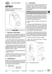
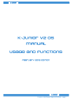
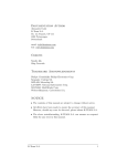
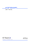
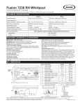
KJ-Genio
User manual
Version 1.0
June 2010
K-Junior Gripper User Manual rev 1.0
2
Documentation Author
Frederic Lambercy
K-Team S.A.
Rue Galilee 9, Y-Park
1400 Yverdon-les-Bains
Switzerland
Email: [email protected]
Url: www.k-team.com
Trademark Acknowledgements:
IBM PC: International Business Machines Corp.
Macintosh: Apple Corp.
SUN Sparc-Station: SUN Microsystems Corp.
LabVIEW: National Instruments Corp.
Matlab: MathWorks Corp.
K-Junior: K-Team.
LEGAL NOTICE:
•
•
•
The contents of this manual are subject to change without notice
All efforts have been made to ensure the accuracy of the content of this manual.
However, should any error be detected, please inform K-Team.
The above notwithstanding, K-Team can assume no responsibility for any error in this
manual.
K-Junior Gripper User Manual rev 1.0
3
TABLE OF CONTENTS
1
INTRODUCTION ................................................................................................. 5
1.1
1.2
1.3
2
CONNECTION...................................................................................................... 6
2.1
2.2
3
INSTALL ...................................................................................................................... 6
UNINSTALL.................................................................................................................. 6
THE K-JUNIOR GENIO...................................................................................... 7
3.1
3.2
3.3
3.4
4
HOW TO USE THIS HANDBOOK ..................................................................................... 5
SAFETY PRECAUTIONS ................................................................................................. 5
RECYCLING ................................................................................................................. 5
OVERVIEW .................................................................................................................. 7
I2C ADDRESS ............................................................................................................... 7
REGISTER ADDRESS .................................................................................................... 8
ELECTRONICS ............................................................................................................ 11
USE ....................................................................................................................... 12
4.1
4.2
PROGRAMMING IN C LANGUAGE ............................................................................... 12
SERIAL PORT CONTROL ............................................................................................. 13
A
TECHNICAL SPECIFICATION ...................................................................... 14
B
CONNECTORS ................................................................................................... 15
K-Junior Gripper User Manual rev 1.0
4
1 INTRODUCTION
The K-Junior GenIO module allows to develop your own extension by connecting
external components to the 12 digital input/output or to the 5 8-bit analog inputs. On KJunior GenIO, a large area is prebored with a 0.1" spacing in order to solder or wrap your
own component.
1.1
How to use this handbook
This manual introduces the K-Junior GenIO module dedicated to K-Junior robot. If the
manual do not answer to a question, please consult K-Team website (www.k-team.com)
and in particular the Forum and the FAQs
1.2
Safety precautions
Here are some recommendations on how to correctly use the K-Junior Robot and the
GenIO:
• Keep out from the wet places! A contact with water can made a short circuit and
damage the electronics.
• Don't plug or unplug any connector or turret when the robot is powered! All
connections and turret insertions must be made when the robot and the interface
are switched OFF. Otherwise damages can occur.
• Never leave the K-Junior powered when it is unused. When you have finished
working with K-Junior, turn it off. It will save the battery life
1.3
Recycling
Think about the end of life of your robot! Parts of the robot can be recycled and it is
important to do so. It is for instance important to keep batteries out of the solid waste
stream. When you throw away a battery, it eventually ends up in a landfill or municipal
incinerator. These batteries, which contain Lithium Polymer, can contribute to the toxicity
levels of landfills or incinerator ash. By recycling the batteries through recycling
programs, you can help to create a cleaner and safer environment for generations to come.
For those reasons please take care to the recycling of your robot at the end of its life cycle,
for instance sending back the robot to the manufacturer or to your local dealer.
Thanks for your contribution to a cleaner environment!
K-Junior Gripper User Manual rev 1.0
5
2 Connection
Installing and uninstalling the extension module is delicate. Please read carefully
instructions below to avoid damages. K-TEAM will not take in charge damages caused
by a wrong manipulation.
2.1
Install
Start by checking that robot is switched Off, then insert K-Junior GenIO as much
vertical as possible and according to the orientation below:
Figure 2.1: K-Junior GenIO module top view
Please do not attempt to insert K-Junior GenIO in a different orientation or slightly biased, it
could cause important damages to K-Junior or the extension module.
2.2
Uninstall
Check first that the K-Junior Robot is switched off, hold firmly the K-Junior in your
hand, pull as much vertical as possible the K-Junior GenIO module with the other hand.
Please take extra care in not bending connector pins.
K-Junior Gripper User Manual rev 1.0
6
3
The K-Junior GenIO
3.1
Overview
Figure 3.1: Overview of the GenIO turret layout
Make an external inspection of the turret. Note the location of the following parts:
1.
K-Junior Extension Connectors
2.
Digital I/O Connector
3.
Led
4.
Processor
5.
Module reprogramming connector
6.
Connector for power supply, analog inputs and I2C Bus
3.2
I2C Address
The K-Junior Robot control the GenIO through an I2C bus. The turret address is
defined by 7 bits + 1 bit for the mode selection "write" or "read"
1 0 0 1 0 1 1 R/W
The GenIO I2C address is 0xD1 in "read" mode and 0xD0 in "write mode".
K-Junior Gripper User Manual rev 1.0
7
3.3
Register Address
To get values of inputs or to define the state of an output, you need to access to the
registers as follows below
•
•
•
Along this section, we will use the following notation:
R : for a "Read" only register.
W : for a "Write" only register
R&W : for a "Read" and a "Write" register.
3.3.1 Firmware version register
Description : allow to read firmware version in processor memory.
Address :
0 (0x00)
Access :
R
3.3.2 A0 Analog Input Register
Description : allow to obtain the 8-bit value of the analog input A0.
Address :
16 (0x10)
Access :
R
3.3.3 A1 Analog Input Register
Description : allow to obtain the 8-bit value of the analog input A1.
Address :
17 (0x11)
Access :
R
3.3.4 A2 Analog Input Register
Description : allow to obtain the 8-bit value of the analog input A2.
Address :
18 (0x12)
Access :
R
3.3.5 A3 Analog Input Register
Description : allow to obtain the 8-bit value of the analog input A3.
Address :
19 (0x13)
Access :
R
3.3.6 A4 Analog Input Register
Description : allow to obtain the 8-bit value of the analog input A4.
Address :
20 (0x14)
Access :
R
K-Junior Gripper User Manual rev 1.0
8
3.3.7 A0-A4 Analog Input Register
Description : allow to obtain the 8-bit value of all the analog inputs in the order A0 to A4.
Address :
21 (0x15)
Access :
R
3.3.8 D0 Digital I/O Register
Description : in write mode, this pin acts as an output, while in read mode, this pin acts as an
input.
Address :
32 (0x20)
Access :
R&W
3.3.9 D1 Digital I/O Register
Description : in write mode, this pin acts as an output, while in read mode, this pin acts as an
input.
Address :
33 (0x21)
Access :
R&W
3.3.10 D2 Digital I/O Register
Description : in write mode, this pin acts as an output, while in read mode, this pin acts as an
input.
Address :
34 (0x22)
Access :
R&W
3.3.11 D3 Digital I/O Register
Description : in write mode, this pin acts as an output, while in read mode, this pin acts as an
input.
Address :
35 (0x23)
Access :
R&W
3.3.12 D4 Digital I/O Register
Description : in write mode, this pin acts as an output, while in read mode, this pin acts as an
input.
Address :
36 (0x24)
Access :
R&W
3.3.13 D5 Digital I/O Register
Description : in write mode, this pin acts as an output, while in read mode, this pin acts as an
input.
Address :
37 (0x25)
Access :
R&W
K-Junior Gripper User Manual rev 1.0
9
3.3.14 D6 Digital I/O Register
Description : in write mode, this pin acts as an output, while in read mode, this pin acts as an
input.
Address :
38 (0x26)
Access :
R&W
3.3.15 D7 Digital I/O Register
Description : in write mode, this pin acts as an output, while in read mode, this pin acts as an
input.
Address :
39 (0x27)
Access : R&W
3.3.16 D8 Digital I/O Register
Description : in write mode, this pin acts as an output, while in read mode, this pin acts as an
input.
Address :
40 (0x28)
Access :
R&W
3.3.17 D9 Digital I/O Register
Description : in write mode, this pin acts as an output, while in read mode, this pin acts as an
input.
Address :
41 (0x29)
Access :
R&W
3.3.18 D10 Digital I/O Register
Description : in write mode, this pin acts as an output, while in read mode, this pin acts as an
input.
Address :
48 (0x30)
Access :
R&W
3.3.19 D11 Digital I/O Register
Description : in write mode, this pin acts as an output, while in read mode, this pin acts as an
input.
Address :
49 (0x31)
Access :
R&W
3.3.20 I2C Address Change
Description : this register allows to modify the I2C module address. The new address is
stored in EEPROM, so that you do not need to modify on reboot. You need to
specify a new even address in write mode register, e.g., 0xA0. If you enter an
odd address, e.g., 0x51, the module will default to its default base address:
0xD0.
Address :
96 (0x60)
Access :
W
K-Junior Gripper User Manual rev 1.0
10
3.4
Electronics
Please note that in order to avoid erroneous reading when reading an unconnected
input, all I/Os, either digital or analog, are connected to a 100-kOhm pull-down resistor (see
schematics below).
Figure 3.4: Pull-Down Schematics
K-Junior Gripper User Manual rev 1.0
11
4
Use
There is two ways to use K-Junior GenIO:
• Program it in C using CCS C Compiler (non provided).
• Control it via serial port either using your own software, or using for instance
SysQuake LE.
4.1
Programming in C language
To program K-Junior in C, you must acquire CCS C compiler (http://www.kteam.com/mobile-robotics-products/k-junior/software#acp). We recommend that you first
read
the
latest
version
of
the
KJOs
manual
(http://ftp.k-team.com/KJunior/KJOSManual.doc). This manual provides all necessary information about installing
and using CCS on K-Junior modules.
• Download the latest version of KJOs, as well as the latest version of K-Junior GenIO
Lib including HemGenIO.h.
• Open the project using CCS C Compiler.
To use the following functions, you must first include HemGenIO.h at the beginning of your
code: #include "HemGenIO.h" HemGenIO.h must be in your project’s directory.
HemGenIO.h includes the following functions:
4.1.1 char HemGenIO_Init(void)
Goal:
Initialize HemGenIO module. You must call this fonction first when using
HemGenIO module.
Example :
HemGenIOInit();
4.1.2 char HemGenIO_Read_Version(void)
Goal:
Read the HemGenIO firmware version. Exemple : char Version; Version =
HemGenIOReadVersion();
4.1.3 int1 HemGenIO_Read_Digital(char input)
Goal:
Return state (0 or 1) of a digital input. The input parameter allows to select the
input (0 to 11). Example : int1 StateIODig1; StateIODig1 =
HemGenIOReadDigital(1);
4.1.4 void HemGenIO_Write_Digital(char input, int1 state)
Goal:
Define the state of a digital output. The first parameter selects the output (0 to
11), while the seconds defines its state (0 or 1) Example :
HemGenIOWriteDigital(9,0); // Clear D9 to 0 (GND)
K-Junior Gripper User Manual rev 1.0
12
4.1.5 char HemGenIO_Read_Analog(char input)
Goal:
Returns a 8-bit analog value (0 = 0V , 255 = 5V) of an analog input (0 to 4)
Example :
char Analog2Value; Analog2Value = HemGenIOReadAnalog(2);
4.2
Serial Port Control
Thanks to the K-Junior firmware you can access to I2C modules via the RS232
command line. For that, please refer to the latest K-Junior user manual.
Examples :
• W,D0,26,01 : digital output D6 set to 1 (5V).
• R,D0,00,01 : returns firmware version.
You can use any development environment that can access serial port to interface to KJunior GenIO. For instance, we developed a graphical interface to read and configure the KJunior GenIO. You must first plug your K-Junior GenIO to the K-Junior, turn on the robot
and then connect the PC to the K-Junior with the USB cable.
K-Junior Gripper User Manual rev 1.0
13
A
Technical Specification
•
•
•
•
•
•
•
Weight : NC
Power Supply : 5 [V]
I2C Max. Freq.: 400 [kHz]
Analog input number: 5
A/D Converter resolution: 8 [bits]
Digital input number: 12
Maximum Output Current of a digital output: 25 [mA]
K-Junior Gripper User Manual rev 1.0
14
B
Connectors
Figure B.1: Connector Details
•
•
•
•
•
•
D0-D11: Digital input/output
A0-A4: Analog input
SCL,SDA: I2C bus signals
5V: 5V power supply
GND: Ground
RB6,RB7,MCLR,GND,VCC_PIC: Processor Reprogramming Signals (see K-Junior
FlexExtProg and K-Junior IcdAdaptor)
K-Junior Gripper User Manual rev 1.0
15
K-Team S.A.
Rue Galilee 9
1400 Yverdon-les-bains
Switzerland
K-Junior Gripper User Manual rev 1.0
16