1
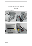
TM-U220
Technical Reference
guide
EPSON
English
Rev. B
404455402
TM-U220 Technical Reference Guide
CAUTIONS
❏
This document shall apply only to the product(s) identified herein.
❏
No part of this document may be reproduced, stored in a retrieval system, or transmitted in any form or by any
means, electronic, mechanical, photocopying, recording, or otherwise, without the prior written permission of
Seiko Epson Corporation.
❏
The contents of this document are subject to change without notice. Please contact us for the latest information.
❏
While every precaution has been taken in the preparation of this document, Seiko Epson Corporation assumes no
responsibility for errors or omissions.
❏
Neither is any liability assumed for damages resulting from the use of the information contained herein.
❏
Neither Seiko Epson Corporation nor its affiliates shall be liable to the purchaser of this product or third parties
for damages, losses, costs, or expenses incurred by the purchaser or third parties as a result of: accident, misuse, or
abuse of this product or unauthorized modifications, repairs, or alterations to this product, or (excluding the U.S.)
failure to strictly comply with Seiko Epson Corporation's operating and maintenance instructions.
❏
Seiko Epson Corporation shall not be liable against any damages or problems arising from the use of any options
or any consumable products other than those designated as Original EPSON Products or EPSON Approved
Products by Seiko Epson Corporation.
TRADEMARKS
EPSON®
and
Microsoft®
ESC/POS®
are registered trademarks of Seiko Epson Corporation.
Windows® and
Windows NT® are registered trademarks of Microsoft Corporation.
General Notice: Other product and company names used herein are for identification purposes only and may be
trademarks of their respective companies.
ESC/POS Proprietary Command System
EPSON took the initiative by introducing ESC/POS, a proprietary POS printer command system including patented
commands and enabling versatile POS system construction with high scalability. Compatible with all types of EPSON
POS printers and displays, this proprietary control system also offers the flexibility to easily make future upgrades. Its
popularity is worldwide.
Revision Information
Rev. B
Revision
Page
Altered Items and Contents
Rev. A
all page
newly authorized
Rev. B
all page
revising about the wall hanging unit and miscellaneous.
i
About This Manual
Aim of the Manual
This manual was created to provide information on the TM-U220 printer for anyone who is
developing hardware, installations, or programs. Programmers will also want to consult other
documents.
Contents of the Manual
ii
Chapter 1, “General Information.”
General description of features plus
specifications.
Chapter 2, “System Planning.”
Contains introduction of control methods and
each connection form.
Chapter 3, “Setup.”
Contains information on such matters as DIP
switches, memory switches, error processing for
using TM-U220.
Chapter 4, “Troubleshooting.”
Contains useful information for using.
Chapter 5, “Application Development
Information.”
Contains useful information for programming.
Chapter 6, “Notices for Replacement of
the TM-U210/TM-U300.”
Contains various notices and comparison
information for using the TM-U220 as a
replacement for the TM-U210/TM-U300.
Appendix A, “Comparison table for TMU220/U210/U300.”
Comparison table for replacing TM-U210/
TM-U300 with the TM-U220.
Appendix C, “Character Code Table.”
Contains the supported character tables.
Appendix D, “Power Supply Unit.”
Describes the external dimensions and
specifications of the power supply units.
Rev. B
TM-U220 Technical Reference Guide
Related Software and Documents
Related software and documents
Rev. B
Software/document name
Description
TM-U220 User’s Manual/
This provides basic handling procedures for the end user of the
printer
TM-U220 Technical Reference Guide
This Manual
ESC/POS Application Programming Guide
This provides descriptions in Acrobat format of the commands
used by each TM printer, along with sample programs and other
information about the printers
EPSON OPOS ADK
This is a OCX driver
EPSON OPOS ADK Manual
This provides information for anyone who is programming using
OPOS. This is included in the EPSON OPOS ADK
EPSON Advanced Printer Driver
This is a Windows driver
EPSON Advanced Printer Driver Manual
This provides information for anyone who is programming using
the APD (EPSON Advanced Printer Driver)
iii
iv
Rev. B
TM-U220 Technical Reference Guide
Safety Precautions
EMC and Safety Standards Applied
Product Name: TM-U220A / TM-U220B / TM-U220D
Model Name: M188A / M188B/ M188D
The following standards are applied only to the printers that are so labeled. (EMC is tested using the EPSON’s power
supply.)
Europe:
CE marking
Safety: TÜV (EN 60950)
North America:
EMI: FCC/ICES-003 Class A
Safety: UL60950/CSA C22.2
No. 60950
Japan:
EMI: VCCI Class A
Oceania:
EMC: AS/NZS 3548 Class B
WARNING
The connection of a non-shielded printer interface cable to this printer will invalidate the EMC standards of this
device.
You are cautioned that changes or modifications not expressly approved by Seiko Epson could void your authority to
operate the equipment.
CE Marking
The printer conforms to the following Directives and Norms
Directive 89/336/EEC
EN 55022 Class B
EN 55024
IEC 61000-4-2
IEC 61000-4-3
IEC 61000-4-4
IEC 61000-4-5
IEC 61000-4-6
IEC 61000-4-11
WARNING
M147C is a Class A product. In a domestic environment these products may cause radio interference in which case the
user may be required to take adequate measures.
Rev. B
v
FCC Compliance Statement For American Users
This equipment has been tested and found to comply with the limits for a Class A digital device, pursuant to Part 15 of
the FCC Rules. These limits are designed to provide reasonable protection against harmful interference when the
equipment is operated in a commercial environment.
This equipment generates, uses, and can radiate radio frequency energy and, if not installed and used in accordance
with the instruction manual, may cause harmful interference to radio communications.
Operation of this equipment in a residential area is likely to cause harmful interference, in which case the user will be
required to correct the interference at his own expense.
For Canadian Users
This Class A digital apparatus complies with Canadian ICES-003.
GEREÄUSCHPEGEL
Gemäß der Dritten Verordnung zum Gerätesicherheitsgesetz (Maschinenlärminformations- Verordnung-3. GSGV) ist
der arbeitsplatzbezogene Geräusch-Emissionswert kleiner als 70 dB(A) (basierend auf ISO 7779).
Key to Symbols
The following symbols are used in the documentation for this product. See the specific warnings
and cautions at appropriate points throughout this guide.
WARNING:
Warnings must be followed carefully to avoid serious bodily injury.
CAUTION:
Cautions must be observed to avoid minor injury to yourself or damage to your
equipment.
Note:
Notes have important information and useful tips on the operation of your printer.
vi
Rev. B
TM-U220 Technical Reference Guide
Safety Precautions
This section presents important information to ensure safe and effective use of this product.
Please read this section carefully and store it in an accessible location.
WARNING:
❏ Shut down your equipment immediately if it produces smoke, a strange odor, or
unusual noise. Continued use may lead to fire or electric shock. Immediately unplug
the equipment and contact your dealer or a Seiko Epson service center for advice.
❏ Never attempt to repair this product yourself. Improper repair work can be
dangerous.
❏ Never disassemble or modify this product. Tampering with this product may result in
injury, fire, or electric shock.
❏ Be sure to use the specified power source. Connection to an improper power source
may cause fire or shock.
❏ Never insert or disconnect the power plug with wet hands. Doing so may result in
severe shock.
❏ Do not allow foreign matter to fall into the equipment. Penetration of foreign objects
may lead to fire or shock.
❏ If water or other liquid spills into this equipment, unplug the power cord immediately,
and then contact your dealer or a Seiko Epson service center for advice.
Continued usage may lead to fire or shock.
❏ Do not place multiple loads on the power outlet (wall outlet). Overloading the outlet
may lead to fire.
❏ Always supply power directly from a standard domestic power outlet.
❏ Handle the power cord with care. Improper handling may lead to fire or shock.
•
Do not modify or attempt to repair the cord.
•
Do not place any object on top of the cord.
•
Avoid excessive bending, twisting, and pulling.
•
Do not place cord near heating equipment.
•
Check that the plug is clean before plugging it in.
•
Be sure to push the prongs all the way in.
❏ If the cord becomes damaged, obtain a replacement from your dealer or a Seiko
Epson service center.
Rev. B
vii
CAUTION:
❏ Do not connect cables other than as described in this manual. Different
connections may cause equipment damage and burning.
❏ Be sure to set this equipment on a firm, stable, horizontal surface.
Product may break or cause injury if it falls.
❏ Do not use in locations subject to high humidity or dust levels.
Excessive humidity and dust may cause equipment damage, fire, or shock.
❏ Do not place heavy objects on top of this product. Never stand or lean on this
product. Equipment may fall or collapse, causing breakage and possible injury.
❏ To ensure safety, please unplug this product prior to leaving it unused for an
extended period.
❏ Do not touch either the thermal or the dot matrix print head or the paper feed
motor. Wait for the heads and the motor to cool. The head and the motor can be
very hot after printing for a long time. Touching them may cause burns.
viii
Rev. B
TM-U220 Technical Reference Guide
Contents
Chapter 1 General Information
1.1 Features . . . . . . . . . . . . . . . . . . . . . . . . . . . . . . . . . . . . . . . . . . . . . . . . . . . . . . . . . .
1.1.1 General . . . . . . . . . . . . . . . . . . . . . . . . . . . . . . . . . . . . . . . . . . . . . . . . . . . . .
1.1.2 Printer handling . . . . . . . . . . . . . . . . . . . . . . . . . . . . . . . . . . . . . . . . . . . . . .
1.1.3 Printing . . . . . . . . . . . . . . . . . . . . . . . . . . . . . . . . . . . . . . . . . . . . . . . . . . . . . .
1.1.4 Software . . . . . . . . . . . . . . . . . . . . . . . . . . . . . . . . . . . . . . . . . . . . . . . . . . . .
1.2 Product Structure . . . . . . . . . . . . . . . . . . . . . . . . . . . . . . . . . . . . . . . . . . . . . . . . .
1.2.1 Printer types . . . . . . . . . . . . . . . . . . . . . . . . . . . . . . . . . . . . . . . . . . . . . . . . .
1.2.2 Standard Parts Included with the Printer . . . . . . . . . . . . . . . . . . . . . . .
1.2.3 Related materials for TM-U220 . . . . . . . . . . . . . . . . . . . . . . . . . . . . . . . .
1.3 Consumables . . . . . . . . . . . . . . . . . . . . . . . . . . . . . . . . . . . . . . . . . . . . . . . . . . . . .
1.3.1 Ribbons . . . . . . . . . . . . . . . . . . . . . . . . . . . . . . . . . . . . . . . . . . . . . . . . . . . . .
1.3.2 Roll paper . . . . . . . . . . . . . . . . . . . . . . . . . . . . . . . . . . . . . . . . . . . . . . . . . . .
1.4 Product Specifications Overview . . . . . . . . . . . . . . . . . . . . . . . . . . . . . . . . . . .
1.5 Printing and paper Specifications . . . . . . . . . . . . . . . . . . . . . . . . . . . . . . . . . .
1.5.1 Autocutter (for Type A / B) . . . . . . . . . . . . . . . . . . . . . . . . . . . . . . . . . . .
1.5.2 Paper Roll Supply . . . . . . . . . . . . . . . . . . . . . . . . . . . . . . . . . . . . . . . . . . . .
1.5.2.1 Paper Specifications . . . . . . . . . . . . . . . . . . . . . . . . . . . . . . . . . . .
1.5.2.2 Printable Area . . . . . . . . . . . . . . . . . . . . . . . . . . . . . . . . . . . . . . . . .
1.6 Other Specifications . . . . . . . . . . . . . . . . . . . . . . . . . . . . . . . . . . . . . . . . . . . . . . .
1.6.1 EMI and Safety Standards Applied . . . . . . . . . . . . . . . . . . . . . . . . . . . .
1.6.1.1 Printer (TM-U220) . . . . . . . . . . . . . . . . . . . . . . . . . . . . . . . . . . . . . . .
1.6.1.2 AC Adapter C (packaged in ANK model) . . . . . . . . . . . . . . .
1.6.1.3 AC adapter (packaged in Multilingual model (PS-180)) . .
1.6.2 Reliability . . . . . . . . . . . . . . . . . . . . . . . . . . . . . . . . . . . . . . . . . . . . . . . . . . . .
1.6.3 Environmental Conditions . . . . . . . . . . . . . . . . . . . . . . . . . . . . . . . . . . . .
1.6.4 Installation . . . . . . . . . . . . . . . . . . . . . . . . . . . . . . . . . . . . . . . . . . . . . . . . . .
1.7 External Dimensions and Mass . . . . . . . . . . . . . . . . . . . . . . . . . . . . . . . . . . . . . .
1.7.1 External Dimensions and Mass . . . . . . . . . . . . . . . . . . . . . . . . . . . . . . . .
1.7.1.1 Overview (Type A) . . . . . . . . . . . . . . . . . . . . . . . . . . . . . . . . . . . . .
1.7.1.2 Overview (Type B) . . . . . . . . . . . . . . . . . . . . . . . . . . . . . . . . . . . . . .
1.7.1.3 Overview (Type D) . . . . . . . . . . . . . . . . . . . . . . . . . . . . . . . . . . . . .
1-1
1-1
1-1
1-1
1-1
1-2
1-2
1-2
1-3
1-4
1-4
1-4
1-5
1-6
1-8
1-9
1-10
1-11
1-13
1-13
1-13
1-14
1-14
1-15
1-15
1-16
1-17
1-17
1-17
1-18
1-19
Chapter 2 System Planning
2.1 Control Method . . . . . . . . . . . . . . . . . . . . . . . . . . . . . . . . . . . . . . . . . . . . . . . . . . .
2.1.1 Windows Driver (EPSON Advanced Printer Driver) . . . . . . . . . . . . . .
2.1.1.1 General Features of the EPSON Advanced Printer Driver . .
2.1.1.2 EPSON Advanced Printer Driver Components . . . . . . . . . . . .
2.1.1.3 EPSON Advanced Printer Driver Support Environment . . . .
2.1.2 EPSON OPOS ADK . . . . . . . . . . . . . . . . . . . . . . . . . . . . . . . . . . . . . . . . . . .
2.1.2.1 General Features of EPSON OPOS ADK (OPOS Control) . . .
2.1.2.2 EPSON OPOS ADK Contents . . . . . . . . . . . . . . . . . . . . . . . . . . . .
2.1.2.3 EPSON OPOS ADK Supported Environment . . . . . . . . . . . . . . .
2.1.3 ESC/POS Command . . . . . . . . . . . . . . . . . . . . . . . . . . . . . . . . . . . . . . . . .
2.1.4 How to Get a Driver . . . . . . . . . . . . . . . . . . . . . . . . . . . . . . . . . . . . . . . . . .
2.2 Connection Form and Cables . . . . . . . . . . . . . . . . . . . . . . . . . . . . . . . . . . . . .
2.3 Serial Connection . . . . . . . . . . . . . . . . . . . . . . . . . . . . . . . . . . . . . . . . . . . . . . . . .
2.3.1 Stand alone . . . . . . . . . . . . . . . . . . . . . . . . . . . . . . . . . . . . . . . . . . . . . . . . .
2.3.2 Y-connection . . . . . . . . . . . . . . . . . . . . . . . . . . . . . . . . . . . . . . . . . . . . . . . .
2.3.3 Pass-through connections . . . . . . . . . . . . . . . . . . . . . . . . . . . . . . . . . . . .
2.4 Parallel Connection . . . . . . . . . . . . . . . . . . . . . . . . . . . . . . . . . . . . . . . . . . . . . . .
2.5 USB connection . . . . . . . . . . . . . . . . . . . . . . . . . . . . . . . . . . . . . . . . . . . . . . . . . . .
2.6 Ethernet connection . . . . . . . . . . . . . . . . . . . . . . . . . . . . . . . . . . . . . . . . . . . . . .
2-1
2-1
2-1
2-2
2-2
2-3
2-3
2-4
2-5
2-5
2-5
2-6
2-6
2-7
2-7
2-8
2-8
2-8
2-9
ix
Chapter 3 Setup
3.1 Part Name and Basic Operation . . . . . . . . . . . . . . . . . . . . . . . . . . . . . . . . . . . .
3.1.1 Part name . . . . . . . . . . . . . . . . . . . . . . . . . . . . . . . . . . . . . . . . . . . . . . . . . . .
3.1.1.1 Connectors . . . . . . . . . . . . . . . . . . . . . . . . . . . . . . . . . . . . . . . . . . . .
3.1.2 The Control Panel . . . . . . . . . . . . . . . . . . . . . . . . . . . . . . . . . . . . . . . . . . . .
3.1.2.1 LED . . . . . . . . . . . . . . . . . . . . . . . . . . . . . . . . . . . . . . . . . . . . . . . . . . . .
3.1.2.2 Control Panel Buttons . . . . . . . . . . . . . . . . . . . . . . . . . . . . . . . . . . .
3.2 Setup Flow . . . . . . . . . . . . . . . . . . . . . . . . . . . . . . . . . . . . . . . . . . . . . . . . . . . . . . . .
3.3 Printer setup . . . . . . . . . . . . . . . . . . . . . . . . . . . . . . . . . . . . . . . . . . . . . . . . . . . . . . .
3.3.1 Installing or Replacing the Ribbon Cassette . . . . . . . . . . . . . . . . . . . .
3.3.2 Installing the Roll Paper . . . . . . . . . . . . . . . . . . . . . . . . . . . . . . . . . . . . . . .
3.3.2.1 Installing rhe Roll Paper for Type B, D . . . . . . . . . . . . . . . . . . . . .
3.3.2.2 Installing the Roll Paper for Type A . . . . . . . . . . . . . . . . . . . . . . .
3.3.2.3 Replacing the Roll Paper . . . . . . . . . . . . . . . . . . . . . . . . . . . . . . . .
3.3.3 Connecting the Power Supply Unit . . . . . . . . . . . . . . . . . . . . . . . . . . . .
3.3.3.1 Connecting procedure . . . . . . . . . . . . . . . . . . . . . . . . . . . . . . . . .
3.4 Adjusting Various Settings . . . . . . . . . . . . . . . . . . . . . . . . . . . . . . . . . . . . . . . . . .
3.4.1 How to Confirm Current Settings . . . . . . . . . . . . . . . . . . . . . . . . . . . . . .
3.4.2 Adjusting the DIP Switches . . . . . . . . . . . . . . . . . . . . . . . . . . . . . . . . . . . .
3.4.2.1 When the letters are STD . . . . . . . . . . . . . . . . . . . . . . . . . . . . . . . .
3.4.2.2 When the letters are US . . . . . . . . . . . . . . . . . . . . . . . . . . . . . . . . .
3.4.2.3 Notes for DIP switch 2-1 . . . . . . . . . . . . . . . . . . . . . . . . . . . . . . . . .
3.4.3 Memory Switches . . . . . . . . . . . . . . . . . . . . . . . . . . . . . . . . . . . . . . . . . . . .
3.4.4 Memory Switch Setup Mode . . . . . . . . . . . . . . . . . . . . . . . . . . . . . . . . . .
3.4.4.1 Starting the memory switch setup mode . . . . . . . . . . . . . . . . .
3.4.4.2 Ending memory switch setting mode . . . . . . . . . . . . . . . . . . . .
3.4.4.3 Operating procedure . . . . . . . . . . . . . . . . . . . . . . . . . . . . . . . . . . .
3.4.5 Adjusting Roll paper width . . . . . . . . . . . . . . . . . . . . . . . . . . . . . . . . . . . .
3.4.6 Adjusting Position of Roll Paper Near End Detector . . . . . . . . . . . . .
3.4.7 Select Autocutter action . . . . . . . . . . . . . . . . . . . . . . . . . . . . . . . . . . . . .
3.4.8 Connecting the Printer to the Host PC / POS Terminal . . . . . . . . . .
3.4.8.1 Serial Interface model . . . . . . . . . . . . . . . . . . . . . . . . . . . . . . . . . .
3.4.8.2 Parallel Interface Models . . . . . . . . . . . . . . . . . . . . . . . . . . . . . . . .
3.4.8.3 USB Interface Models . . . . . . . . . . . . . . . . . . . . . . . . . . . . . . . . . . .
3.4.8.4 Ethernet interface . . . . . . . . . . . . . . . . . . . . . . . . . . . . . . . . . . . . . .
3.4.8.5 Connecting a Drawer . . . . . . . . . . . . . . . . . . . . . . . . . . . . . . . . . .
3.5 Install a Printer Driver in the Host PC / POS Terminal . . . . . . . . . . . . . . . . . .
3.5.1 OPOS . . . . . . . . . . . . . . . . . . . . . . . . . . . . . . . . . . . . . . . . . . . . . . . . . . . . . . .
3.5.1.1 Install and Set up. . . . . . . . . . . . . . . . . . . . . . . . . . . . . . . . . . . . . . . .
3.5.1.2 Package contents of EPSON OPOS ADK. . . . . . . . . . . . . . . . . .
3.5.2 Advanced Printer Driver (APD) . . . . . . . . . . . . . . . . . . . . . . . . . . . . . . . .
3.5.2.1 Installing and Setting Up . . . . . . . . . . . . . . . . . . . . . . . . . . . . . . . .
3.6 Self Test . . . . . . . . . . . . . . . . . . . . . . . . . . . . . . . . . . . . . . . . . . . . . . . . . . . . . . . . . . .
3.6.1 Self Test Procedure . . . . . . . . . . . . . . . . . . . . . . . . . . . . . . . . . . . . . . . . . . .
3-1
3-1
3-1
3-2
3-2
3-3
3-4
3-6
3-6
3-7
3-8
3-9
3-12
3-13
3-13
3-14
3-14
3-15
3-15
3-17
3-18
3-18
3-20
3-21
3-21
3-22
3-25
3-26
3-27
3-29
3-30
3-30
3-30
3-32
3-33
3-33
3-33
3-33
3-36
3-37
3-37
3-39
3-39
Chapter 4 Troubleshooting
4.1 LED Blinking Pattern . . . . . . . . . . . . . . . . . . . . . . . . . . . . . . . . . . . . . . . . . . . . . . . .
4.1.1 Error Types . . . . . . . . . . . . . . . . . . . . . . . . . . . . . . . . . . . . . . . . . . . . . . . . . . .
4.1.1.1 Errors that automatically recover . . . . . . . . . . . . . . . . . . . . . . . . . .
4.1.1.2 Recoverable Errors . . . . . . . . . . . . . . . . . . . . . . . . . . . . . . . . . . . . . . .
4.1.1.3 Errors that are impossible to recover: . . . . . . . . . . . . . . . . . . . . . . .
4.2 Removing a Paper Jam . . . . . . . . . . . . . . . . . . . . . . . . . . . . . . . . . . . . . . . . . . . .
4.3 Autocutter Jam . . . . . . . . . . . . . . . . . . . . . . . . . . . . . . . . . . . . . . . . . . . . . . . . . . .
4.4 Printer Stops Printing / Printer Repeats Printing on a Line . . . . . . . . . . . . . .
4.5 Printer prints “?“ or Incorrect Data With Serial Interface . . . . . . . . . . . . . .
4.6 Print Speed is Slow When Using Windows Printer Driver . . . . . . . . . . . . . . .
4.7 Hexadecimal Dump mode . . . . . . . . . . . . . . . . . . . . . . . . . . . . . . . . . . . . . . . . .
x
4-1
4-1
4-1
4-2
4-2
4-3
4-3
4-4
4-7
4-7
4-7
TM-U220 Technical Reference Guide
Chapter 5 Application Development Information
5.1 Various Status Categories . . . . . . . . . . . . . . . . . . . . . . . . . . . . . . . . . . . . . . . . . .
5.1.1 Printer Status on APD . . . . . . . . . . . . . . . . . . . . . . . . . . . . . . . . . . . . . . . . .
5.1.2 OPOS . . . . . . . . . . . . . . . . . . . . . . . . . . . . . . . . . . . . . . . . . . . . . . . . . . . . . . .
5.1.2.1 Checking the printer state . . . . . . . . . . . . . . . . . . . . . . . . . . . . . . . .
5.1.2.2 Printer Errors and Status . . . . . . . . . . . . . . . . . . . . . . . . . . . . . . . . .
5.1.2.3 ESC/POS commands . . . . . . . . . . . . . . . . . . . . . . . . . . . . . . . . . . . .
5.2 Cash Drawer Control . . . . . . . . . . . . . . . . . . . . . . . . . . . . . . . . . . . . . . . . . . . . . .
5.2.1 Advanced Printer Driver . . . . . . . . . . . . . . . . . . . . . . . . . . . . . . . . . . . . . .
5.2.1.1 Drawer Open . . . . . . . . . . . . . . . . . . . . . . . . . . . . . . . . . . . . . . . . . . .
5.2.1.2 Checking Drawer Status . . . . . . . . . . . . . . . . . . . . . . . . . . . . . . . . . .
5.2.2 OPOS . . . . . . . . . . . . . . . . . . . . . . . . . . . . . . . . . . . . . . . . . . . . . . . . . . . . . . .
5.2.2.1 Drawer Open/Close . . . . . . . . . . . . . . . . . . . . . . . . . . . . . . . . . . . . .
5.2.2.2 Checking Drawer Status . . . . . . . . . . . . . . . . . . . . . . . . . . . . . . . . . .
5.2.3 ESC/POS . . . . . . . . . . . . . . . . . . . . . . . . . . . . . . . . . . . . . . . . . . . . . . . . . . . .
5.3 NV memory . . . . . . . . . . . . . . . . . . . . . . . . . . . . . . . . . . . . . . . . . . . . . . . . . . . . . . .
5.4 NV Bit-image Printing . . . . . . . . . . . . . . . . . . . . . . . . . . . . . . . . . . . . . . . . . . . . . .
5.4.1 Advanced Printer Driver . . . . . . . . . . . . . . . . . . . . . . . . . . . . . . . . . . . . . .
5.4.1.1 How to print “NV Bit-image“ . . . . . . . . . . . . . . . . . . . . . . . . . . . . .
5.4.1.2 Printable bitmap format in APD . . . . . . . . . . . . . . . . . . . . . . . . . . .
5.4.2 OPOS . . . . . . . . . . . . . . . . . . . . . . . . . . . . . . . . . . . . . . . . . . . . . . . . . . . . . . .
5.4.2.1 Printing method . . . . . . . . . . . . . . . . . . . . . . . . . . . . . . . . . . . . . . . . .
5.4.2.2 LetterQuality . . . . . . . . . . . . . . . . . . . . . . . . . . . . . . . . . . . . . . . . . . .
5.4.2.3 Setting of printing position by escape sequence . . . . . . . . .
5.4.2.4 Printable bitmap format in OPOS . . . . . . . . . . . . . . . . . . . . . . . . . .
5.4.3 ESC/POS command . . . . . . . . . . . . . . . . . . . . . . . . . . . . . . . . . . . . . . . . .
5.5 Printing for journal used . . . . . . . . . . . . . . . . . . . . . . . . . . . . . . . . . . . . . . . . . . . .
5.6 FAQ List . . . . . . . . . . . . . . . . . . . . . . . . . . . . . . . . . . . . . . . . . . . . . . . . . . . . . . . . . . .
5.6.1 Q. Drawer kick does not operate properly. . . . . . . . . . . . . . . . . . . . .
5.6.1.1 A. Drawer specifications differ, depending on
the manufacturer and the part number. . . . . . . . . . . . . . . . . . .
5.6.2 Q. Unable to print a part of Page 0 in Visual Basic. . . . . . . . . . . . . .
5.6.2.1 A. Follow the procedure . . . . . . . . . . . . . . . . . . . . . . . . . . . . . . . . . .
5-1
5-1
5-2
5-2
5-3
5-3
5-4
5-4
5-4
5-5
5-5
5-5
5-5
5-6
5-6
5-8
5-8
5-8
5-8
5-8
5-8
5-9
5-9
5-9
5-9
5-10
5-10
5-10
5-10
5-11
5-11
Chapter 6 Notices for Replacement of the TM-U210/TM-U300
6.1 For Replacement of the TM-U210 . . . . . . . . . . . . . . . . . . . . . . . . . . . . . . . . . . . 6-1
6.1.1 About printing format compatibility . . . . . . . . . . . . . . . . . . . . . . . . . . . 6-1
6.1.1.1 Printing area . . . . . . . . . . . . . . . . . . . . . . . . . . . . . . . . . . . . . . . . . . . . 6-1
6.1.1.2 Characters . . . . . . . . . . . . . . . . . . . . . . . . . . . . . . . . . . . . . . . . . . . . . . 6-2
6.1.1.3 Cutting position from print start position . . . . . . . . . . . . . . . . . . . 6-2
6.1.2 Cutting Method . . . . . . . . . . . . . . . . . . . . . . . . . . . . . . . . . . . . . . . . . . . . . 6-3
6.1.3 Dimensions . . . . . . . . . . . . . . . . . . . . . . . . . . . . . . . . . . . . . . . . . . . . . . . . . . 6-4
6.1.4 Receive buffer size . . . . . . . . . . . . . . . . . . . . . . . . . . . . . . . . . . . . . . . . . . . 6-4
6.1.4.1 Effect on the application when condition of buffer full is changed 6-4
6.1.4.2 Effect on the application in the condition of release full state . . 6-5
6.1.5 Accessories compatibility . . . . . . . . . . . . . . . . . . . . . . . . . . . . . . . . . . . . 6-5
6.1.5.1 Power supply unit . . . . . . . . . . . . . . . . . . . . . . . . . . . . . . . . . . . . . . . 6-5
6.1.5.2 Consumable compatibility . . . . . . . . . . . . . . . . . . . . . . . . . . . . . . . . 6-5
6.1.6 Provided statuses . . . . . . . . . . . . . . . . . . . . . . . . . . . . . . . . . . . . . . . . . . . . 6-5
6.1.7 Use for Journal . . . . . . . . . . . . . . . . . . . . . . . . . . . . . . . . . . . . . . . . . . . . . . . 6-8
6.1.8 New functions added . . . . . . . . . . . . . . . . . . . . . . . . . . . . . . . . . . . . . . . . 6-8
6.1.8.1 Wall hanging . . . . . . . . . . . . . . . . . . . . . . . . . . . . . . . . . . . . . . . . . . . 6-8
6.1.8.2 NV bit-image . . . . . . . . . . . . . . . . . . . . . . . . . . . . . . . . . . . . . . . . . . . 6-8
6.1.8.3 User NV memory . . . . . . . . . . . . . . . . . . . . . . . . . . . . . . . . . . . . . . . . 6-8
6.1.8.4 Memory Switch and memory switch setup mode . . . . . . . . . . . . 6-9
6.1.9 Driver compatibility . . . . . . . . . . . . . . . . . . . . . . . . . . . . . . . . . . . . . . . . . . 6-9
xi
6.1.9.1 Advanced Printer Driver . . . . . . . . . . . . . . . . . . . . . . . . . . . . . . . . . . 6-9
6.1.9.2 OPOS . . . . . . . . . . . . . . . . . . . . . . . . . . . . . . . . . . . . . . . . . . . . . . . . . . 6-9
6.1.9.3 ESC/POS command (Direct control) . . . . . . . . . . . . . . . . . . . . . . . 6-9
6.2 For Replacement of the TM-U300 . . . . . . . . . . . . . . . . . . . . . . . . . . . . . . . . . . . 6-9
6.2.1 About Printing format compatibility . . . . . . . . . . . . . . . . . . . . . . . . . . . 6-9
6.2.1.1 Printing area . . . . . . . . . . . . . . . . . . . . . . . . . . . . . . . . . . . . . . . . . . . . 6-10
6.2.1.2 Characters . . . . . . . . . . . . . . . . . . . . . . . . . . . . . . . . . . . . . . . . . . . . . . 6-10
6.2.1.3 Cutting position from print start position . . . . . . . . . . . . . . . . . . . 6-11
6.2.2 Cutting Method . . . . . . . . . . . . . . . . . . . . . . . . . . . . . . . . . . . . . . . . . . . . . . 6-12
6.2.3 Dimensions . . . . . . . . . . . . . . . . . . . . . . . . . . . . . . . . . . . . . . . . . . . . . . . . . . 6-12
6.2.4 Receive buffer size . . . . . . . . . . . . . . . . . . . . . . . . . . . . . . . . . . . . . . . . . . . 6-12
6.2.4.1 Effect to the application when condition of buffer full is changed 6-13
6.2.4.2 Effect to the application when condition of release full state . . . 6-13
6.2.5 Accessories compatibility . . . . . . . . . . . . . . . . . . . . . . . . . . . . . . . . . . . . . 6-13
6.2.5.1 Power supply unit . . . . . . . . . . . . . . . . . . . . . . . . . . . . . . . . . . . . . . . 6-13
6.2.5.2 Consumables compatibility . . . . . . . . . . . . . . . . . . . . . . . . . . . . . . . 6-13
6.2.6 Provided statuses and detectors . . . . . . . . . . . . . . . . . . . . . . . . . . . . . . 6-14
6.2.6.1 Newly added Status . . . . . . . . . . . . . . . . . . . . . . . . . . . . . . . . . . . . . . 6-14
6.2.7 Use for Journal . . . . . . . . . . . . . . . . . . . . . . . . . . . . . . . . . . . . . . . . . . . . . . . 6-14
6.2.8 Added new functions . . . . . . . . . . . . . . . . . . . . . . . . . . . . . . . . . . . . . . . . 6-14
6.2.8.1 Wall hanging . . . . . . . . . . . . . . . . . . . . . . . . . . . . . . . . . . . . . . . . . . . . 6-14
6.2.8.2 NV bit-image . . . . . . . . . . . . . . . . . . . . . . . . . . . . . . . . . . . . . . . . . . . . 6-14
6.2.8.3 User NV memory . . . . . . . . . . . . . . . . . . . . . . . . . . . . . . . . . . . . . . . . 6-14
6.2.8.4 Memory Switch and Memory Switch setting mode . . . . . . . . . . . 6-14
6.2.9 Driver compatibility . . . . . . . . . . . . . . . . . . . . . . . . . . . . . . . . . . . . . . . . . . 6-14
6.2.9.1 Advanced Printer Driver . . . . . . . . . . . . . . . . . . . . . . . . . . . . . . . . . . 6-14
6.2.9.2 OPOS . . . . . . . . . . . . . . . . . . . . . . . . . . . . . . . . . . . . . . . . . . . . . . . . . . 6-16
6.2.10 ESC/POS command (Directly control) . . . . . . . . . . . . . . . . . . . . . . . . 6-16
Appendix A Comparison table for TM-U220/U210/U300
Appendix B Character Code Table
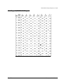
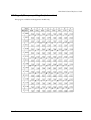
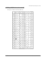
B.1 Page 0 (PC437: USA, Standard Europe) . . . . . . . . . . . . . . . . . . . . . . . . . . . .
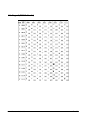
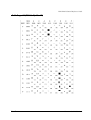
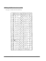
B.2 Page 1 (Katakana) . . . . . . . . . . . . . . . . . . . . . . . . . . . . . . . . . . . . . . . . . . . . . . .
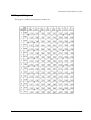
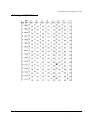
B.3 Page 2 (PC850: Multilingual) . . . . . . . . . . . . . . . . . . . . . . . . . . . . . . . . . . . . . . .
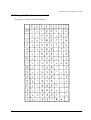
B.4 Page 3 (PC860: Portuguese) . . . . . . . . . . . . . . . . . . . . . . . . . . . . . . . . . . . . . . .
B.5 Page 4 (PC863: Canadian-French) . . . . . . . . . . . . . . . . . . . . . . . . . . . . . . . . .
B.6 Page 5 (PC865: Nordic) . . . . . . . . . . . . . . . . . . . . . . . . . . . . . . . . . . . . . . . . . . .
B.7 Page 6 (Hiragana) . . . . . . . . . . . . . . . . . . . . . . . . . . . . . . . . . . . . . . . . . . . . . . . . . . .
B.8 Page 7 (One-pass printing Kanji characters) . . . . . . . . . . . . . . . . . . . . . . . . . . . .
B.9 Page 8 (One-pass printing Kanji characters) . . . . . . . . . . . . . . . . . . . . . . . . . . . .
B.10 Page 16 (WPC1252) . . . . . . . . . . . . . . . . . . . . . . . . . . . . . . . . . . . . . . . . . . . . . .
B.11 Page 17 (PC866: Cyrillic #2) . . . . . . . . . . . . . . . . . . . . . . . . . . . . . . . . . . . . . . .
B.12 Page 18 (PC852: Latin2) . . . . . . . . . . . . . . . . . . . . . . . . . . . . . . . . . . . . . . . . . .
B.13 Page 19 (PC858: Euro) . . . . . . . . . . . . . . . . . . . . . . . . . . . . . . . . . . . . . . . . . . .
B.14 Page 20 (Thai character code 42) . . . . . . . . . . . . . . . . . . . . . . . . . . . . . . . .
B.15 Page 21 (Thai character code 11) . . . . . . . . . . . . . . . . . . . . . . . . . . . . . . . .
B.16 Page 22 (Thai character code 13) . . . . . . . . . . . . . . . . . . . . . . . . . . . . . . . .
B.17 Page 23 (Thai character code 14) . . . . . . . . . . . . . . . . . . . . . . . . . . . . . . . .
B.18 Page 24 (Thai character code 16) . . . . . . . . . . . . . . . . . . . . . . . . . . . . . . . .
B.19 Page 25 (Thai character code 17) . . . . . . . . . . . . . . . . . . . . . . . . . . . . . . . .
B.20 Page 26 (Thai character code 18) . . . . . . . . . . . . . . . . . . . . . . . . . . . . . . . .
B.21 Page 254 (Blank page) . . . . . . . . . . . . . . . . . . . . . . . . . . . . . . . . . . . . . . . . . . .
B.22 Page 255 (Blank page) . . . . . . . . . . . . . . . . . . . . . . . . . . . . . . . . . . . . . . . . . . .
B.23 International Character Sets . . . . . . . . . . . . . . . . . . . . . . . . . . . . . . . . . . . . . .
xii
B-1
B-2
B-3
B-4
B-5
B-6
B-7
B-8
B-9
B-10
B-11
B-12
B-13
B-14
B-15
B-16
B-17
B-18
B-19
B-20
B-21
B-22
B-23
TM-U220 Technical Reference Guide
Appendix C Power Supply Unit
C.1 AC Adapter C . . . . . . . . . . . . . . . . . . . . . . . . . . . . . . . . . . . . . . . . . . . . . . . . . . . . .
C.1.1 Case specifications . . . . . . . . . . . . . . . . . . . . . . . . . . . . . . . . . . . . . . . . . . . .
C.2 PS-180 . . . . . . . . . . . . . . . . . . . . . . . . . . . . . . . . . . . . . . . . . . . . . . . . . . . . . . . . . . . .
C.2.1 Case specifications . . . . . . . . . . . . . . . . . . . . . . . . . . . . . . . . . . . . . . . . . . . .
C.2.2 Usage cautions . . . . . . . . . . . . . . . . . . . . . . . . . . . . . . . . . . . . . . . . . . . . . . .
C-1
C-1
C-2
C-2
C-2
xiii
xiv
TM-U220 Technical Reference Guide
Chapter 1
General Information
1.1 Features
The TM-U220 is a POS printer that can print receipt paper (paper roll).
The TM-U220 is designed to be compatible with existing systems built around a TM-U210.
1.1.1 General
❏ Compact and lightweight.
❏ 3 model types are provided. (See “Printer types” (page 1-2))
❏ Excellent reliability and long life due to adoption of a stepping motor both for moving the
carriage and for paper feeding.
❏ Can be installed hanging on the wall with an optional hanging bracket (only for type B, D).
1.1.2 Printer handling
❏ Easy drop-in paper loading and easy maintenance
❏ Cable connectors are housed in the bottom of the printer.
❏ Built-in two drawer kickout interface connectors
❏ Built-in autocutter (for type A or B)
❏ Built-in take-up device (for type A)
1.1.3 Printing
❏ High-speed printing through logic-seeking control
❏ Two-color printing (black and red)
❏ Can print on various paper wide range (for type B or D: 76 / 69.5 / 57.5 mm)
1.1.4 Software
❏ Command protocol is based on the ESC/POS proprietary command system.
❏ OPOS ADK and Windows printer driver are available.
❏ Automatic status back (ASB) function that automatically transmits changes in printer status.
Rev. B
General Information 1-1
1.2 Product Structure
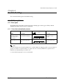
1.2.1 Printer types
TM-U220 has 3 model types: A, B, D. The features are as following.
Type A
Type B
Type D
Two color printing
Yes
Yes
Yes
Autocutter
Yes
Yes
No
Take up device
Yes
No
No
paper width (mm)
76
76/ 69.5/ 57.5
76/ 69.5/ 57.5
wall hanging install
No
Yes
Yes
Supported
language
Alphanumeric model:
alphanumeric
Multilingual model
It supports
alphanumeric and
printing with one of the
following:
• Japanese Kanji
• Simplified Chinese
• Traditional Chinese
• Korean
• Thai
Alphanumeric model:
alphanumeric
Multilingual model
It supports
alphanumeric and
printing with one of the
following:
• Japanese Kanji
• Simplified Chinese
• Traditional Chinese
• Korean
• Thai
Alphanumeric model:
alphanumeric
Multilingual model
It supports
alphanumeric and
printing with one of the
following:
• Japanese Kanji
• Simplified Chinese
• Traditional Chinese
• Korean
• Thai
Near end detector
Factory option
Factory option
Factory option
1.2.2 Standard Parts Included with the Printer
This printer is packed with the materials listed below.
❏ User’s Manual
❏ Roll paper: 1 roll
❏ Power switch cover (using this cover enables you to prevent accidental turning off of the
power)
❏ Exclusive ribbon cassette ERC-38(B/R)
❏ Power supply unit (May not be included with the printer)
Note:
The “AC Adapter. C” which is packed in the carton box of ANK model is not able to use for the
Multilingual model.
*Multilingual means the printer model that can print any one of the following: Japanese Kanji,
Simplified Chinese, Traditional Chinese, Thai characters, or Korean characters.
1-2 General Information
Rev. B
TM-U220 Technical Reference Guide
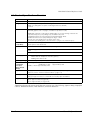
1.2.3 Related materials for TM-U220
TM-U220 has the related materials listed in the following table.
Category
Name
Description
Options
WH-10
This is optional unit for installing on a wall. (Schedule TBD)
DF-10
Affixing Velcro tape
DC-21
This is optional power supply cable to gain power from user’s
power supply.
PS-180
EPSON power supply unit
DM-D105/D205,
DM-D106/DM-D206
Direct connection customer display (available only for some
serial interface models and some USB models)
(See the below NOTE also.)
UB-S01/02,
UB-P02II,
UB-U01II/02II,
UB-E01 etc...)
Various interface boards. (Serial, Parallel, USB, Ethernet
interface)
POS
accessories
DM-D series
These are customer displays. (Line Display)
Consumables
Roll Paper
This is required to print.
Ribbon Casette
This is required to print.
User’s Manual
This manual is packed in the carton box.
Technical
Reference Guide
This Manual.
FAQ about ESC/
POS command
This Manual is Quick Reference of ESC/POS command. and this
has a simple sample program & Tips.
ESC/POS
Application Guide
This Manual is Command Reference Guide of ESC/POS
command. and this has a supplement which has some sample
programs & Tips.
Drivers
(WIndows
environment)
OPOS ADK
This provides the OCX driver which is based upon OPOS. It has
Manuals, sample programs, and TMFlogo utility.
Advanced Printer
Driver
This is a Windows Driver. This Driver has a Manual, Sample
programs, and utilities to use the driver.
Utilities
(WIndows
environment)
Memory Switch
setting Utility
This is a utility to adjust the setting (Memory Switch) of this printer.
See “Memory Switches” (page 3-18) for details.
TMFlogo
This is a utility to store “NV bitmap“ into this printer. It helps
printing “NV bitmap.”
Manuals
Please contact your dealer to get these.
Note:
When you are using the TM-U220 with the “AC Adapter C“ power unit, which is packed in the carton
box of Alphanumeric model, the DM-D series can’t get power from the TM-U220. If you want to provide
power from the TM-U220 to a DM-D, you have to use “PS-180.“
Rev. B
General Information 1-3
1.3 Consumables
1.3.1 Ribbons
This printer needs a ribbon cassette to print receipts. We provide 3 ribbon cassettes:
❏ EPSON ribbon cassette, ERC-38 (B) (Life: 3,000,000 characters / Color: Black)
❏ EPSON ribbon cassette, ERC-38 (P) (Life: 4,000,000 characters / Color: Purple)
❏ EPSON ribbon cassette, ERC-38 (B/R) (Life: 1,500,000 characters / Color: Black)
(Life: 750,000 characters / Color: Red)
Note:
These ribbon cassette life numbers are under the EPSON test conditions.
1.3.2 Roll paper
We provide roll paper and carbon roll paper with 1 copy for this printer. The widths are 76 mm,
69.5 mm, and 57.5 mm {3.00"/2.74"/2.26"}.
1-4 General Information
Rev. B
TM-U220 Technical Reference Guide
1.4 Product Specifications Overview
Print method
serial impact dot matrix
Paper width
76 mm / 69.5 mm / 57.5 mm {3.00"/2.74"/2.26"}
Cut type
There are 2 types. The type can be changed.
Partial cut (cutting with one point on left edge left uncut) (default)
or Full cut
Character sets
95 alphanumeric, 48 international characters,
Extended graphics: 128 × 12 pages. (15 tables for Japanese model)
Multilingual character model supports printing with one of the following character sets:
• Japanese Kanji (Two-pass printing font) (JIS X0208-1990): 6879
• Simplified Chinese (Two-pass printing font) (GB18030-2000): 28553
• Traditional Chinese (Two-pass printing font) (Big 5): 13494
• Korean (Two-pass printing font) (KS C5601 type): 8366
• Thai (Three-pass printing font) : 128 characters × 7 pages (133 character types)
Interface
(compatible)
RS-232C / Bidirectional parallel
Dealer options: USB, 10Base-T I/F
Buffer
Receive buffer: Selectable as 4KB or 40 bytes using a DIP switch 1-2.
Non-volatile graphics data buffer:
128KB
User NV memory: 8KB
Power supply
Power supplied by included AC adapter
ANK model: AC Adapter.C or PS-180 ((option))
Multilingual model: PS-180
Operating voltage
24 VDC ± 7% (optional power supply: EPSON PS-180)
Power
consumption
(except for
drawer kickout
driving)
Operating:Mean: Alphanumeric model: Approximately 31W
Multilingual* model:
Approximately 38W
Standby: Mean: Approximately 2.2W
Temperature
During operation: 0 °C to 50 °C {41°F to 122 °F}. (At 34 °C {93°F} or higher, there are humidity
restrictions; refer to “Environmental Conditions” (page 1-15)
Humidity
During operation:10 to 90% (no condensation)
During storage:10 to 90% (no condensation; excludes paper and ribbon)
Weight (mass)
Type A: Approximately 2.7 kg {5.94 lb}
Type B: Approximately 2.5 kg {5.5 lb}
Type D: Approximately 2.3 kg {5.06 lb}
*Multilingual means the printer model that can print any one of the following: Japanese Kanji, Simplified
Chinese, Traditional Chinese, Thai characters, or Korean characters.
Rev. B
General Information 1-5
1.5 Printing and paper Specifications
Printing method:
Serial impact dot matrix
Head wire
configuration:
9-pin serial configuration
Printing direction:
Bidirectional printing (logic seeking)
Print speed: *1
Approximately 4.7 lps (printing 40 columns per line at 16 cpi)
Approximately 6.0 lps (printing 30 columns per line at 16 cpi, with 1/8"
line spacing)
(except data transmission and processing time)
Paper width:
76 mm / 69.5 mm / 57.5 mm {3.00"/2.74"/2.26"}
Printing width:
63.4 mm / 57 mm / 47.5 mm {2.50" / 2.24" / 1.87"}
Dot positions depend on DIP switch setting. See the table “Dot width
of Printable area” (page 1-7) for details.
Characters per line:
35 (font A), 40 (font B, default) (When using 76mm width paper)
Character spacing:
ANK: 3 half dots (default) or 2 half dots.
Kanji: 2 half dots (default) or 0 half dots.
Thai: 3 half dots (default) or 2 half dots.
The spacing of ANK and Thai characters is selectable by DIP SW2-1.
The spacing of Kanji characters is selectable by ESC/POS command.
Paper feed speed:
30 lps
Line spacing (default): 4.23 mm {1/6"}, programmable by control commands.
Number of characters: 95 alphanumeric, 48 international characters,
Extended graphics: 128 × 12 pages. (15 tables for Japanese model)
Multilingual character model supports printing with one of the
following character sets:
• Japanese Kanji (Two-pass printing font) (JIS X0208-1990): 6879
• Simplified Chinese (Two-pass printing font) (GB18030-2000): 28553
• Traditional Chinese (Two-pass printing font) (Big 5): 13494
• Korean Kanji (Two-pass printing font) (KS C5601 type): 8366
• Thai (Three-pass printing font): 128 characters 7 pages
(133 character types)
Character structure:
Font A: 9 × 9
Font B: 7 × 9
Kanji: 16 × 16
(Font B is the default)
*1 This printer adjusts print speed when it prints high duty characters (Ex. registered characters
on space page or graphic.)
1-6 General Information
Rev. B
TM-U220 Technical Reference Guide
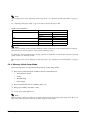
The dot width of the printable area depends on DIP switch setting and paper width as shown in
the following table.
Dot width of Printable area
Paper width
DIP SW2-1 setting
ON
OFF
76 mm
385 half dots
400 half dots
69.5 mm
360 half dots
360 half dots
57.5 mm
297 half dots
300 half dots
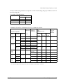
Character Dimensions, Characters Per Inch, Characters Per line
Character
dimensions
Dot spacing
between
characters
Character configuration
Horiz. x
Vert.
7x9
(Font B)
(default)
Condition
of DIP SW
2-1
Character
type
ON
ANK
1.2 x 3.1
2 half dots
Graphic
1.6 x 3.1
0
ANK
1.2 x 3.1
3 half dots
Graphic
1.7 x 3.1
0
ANK
1.6 x 3.1
2 half dots
Graphic
1.9 x 3.1
0
ANK
1.6 x 3.1
3 half dots
Graphic
2.0 x 3.1
0
Kanji
2.7 x 2.7
OFF
(default)
9x9
(Font A)
ON
OFF
(default)
16 x 16
(Kanji
font)
7 x 27
(Thai
font)
9 x 27
(Thai
font)
Regardless
*
ON
Thai
character
OFF
(default)
Thai
character
Characters per
inch (cpi)
(1 inch =
25.4 mm)
WxH
1.2 x 9.5
OFF
(default)
ON
Paper width (mm)
and
Characters per line
(cpl)
1.6 x 9.5
76 mm
69.5 mm
57.5 mm
42
40
33
17.8
40
36
30
16
35
32
27
14.5
33
30
25
13.3
2 half dots
(default) *
22
20
16
8.9
0*
25
22
18
9.5
2 half dots
42
40
33
17.8
3 half dots
40
36
30
16
2 half dots
35
32
27
14.5
3 half dots
33
30
25
13.3
*: The dot spacing between Kanji character is selected by an ESC/POS command.
Rev. B
General Information 1-7
1.5.1 Autocutter (for Type A / B)
Cutting method: By separated-blade scissors
Cutting type:
❏ Partial cut (one point left uncut) (default)
❏ Full cut (completely cut off)
See “Select Autocutter action” (page 3-27) for changing cut type.
Note:
It is recommended to feed approximately 2.116 mm or more in advance before printing to prevent dot
displacement after cutting.
Changing between partial cut and full cut is not controlled by a software command.
The cutting type (partial cut or full cut) must be selected before the printer is first used. If the cutting type
is changed from partial cut to full cut after the printer has been used, the printer may not be reliable
because the wear-out level of the cutter blade differs.
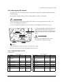
CAUTION:
When the paper is cut completely (full cut) with the printer’s horizontal installation, make
sure to remove the cut paper, then perform the next cut. Never allow several pieces of
the cut paper to remain in the paper exit because double cuts, paper jams, or
autocutter error may occur because the cut paper drops into the paper path.
1-8 General Information
Rev. B
TM-U220 Technical Reference Guide
1.5.2 Paper Roll Supply
Supply method:
Drop-in method
Paper roll end detection:
Detection method: Mechanical microswitch
Detection position: Positioned within the paper path for the
roll paper; detects the end of the roll paper
Near-end detector:
Detection method: Mechanical microswitch
Inner diameter of the roll paper core: 10.5 to 12.5 mm
Near-end adjustment: Adjusting screw
Remaining amount: Fixed position
#1 approximately 8 mm
#2 approximately 5 mm
(The adjusting screw has two positions.)
See“Adjusting Position of Roll Paper Near End Detector”
(page 3-26).
Rev. B
General Information 1-9
1.5.2.1 Paper Specifications
Paper feeding method:
Friction feed
Paper feed interval:
Initial setting: Approximately 4.23mm {1/6"}
Can be set in units of approximately 0.18mm {1/144"} by
ESC/POS command
Paper feed speed:
30 lps (approximately 4.99" /s)
(during continuous feeding)
[lps: lines per second]
Roll paper width:
76 ± 0.5 mm (3" ± 0.02") / 69.5 ± 0.5 mm (2.74" ± 0.02")
/ 57.5 ± 0.5 mm (2.26" ± 0.02")
Maximum diameter:
83 mm (3.27")
Core:
When there is no near-end detector, always be sure to use roll
paper that is not glued to the core.
Normal paper
specifications:
Paper thickness: 1 sheet: 0.06 to 0.085mm {0.0024 to 0.0033"}
Weight: 52.3 to 64 g/m2 {14 to 17 lb}
(45 to 55 kg/1000 sheets 1091 × 788mm)
Carbon paper
specifications:
Number of copies: Original 1 sheet + one copy sheet
Thickness: 0.05 to 0.08 mm {0.002 to 0.0031"}
(thickness of one sheet);
Recommended paper:
Paper by Mitsubishi - Carbonless paper (blue)
Top sheets:
N40Hi (paper thickness: 0.06mm {0.0024"},
mass: 47.2 g/m2 {12.6 lb}
Bottom sheet
N60 (paper thickness: 0.08mm {0.0031"},
mass: 68.0 g/m2 {18 lb}
The copying capability is affected by the ambient temperature,
and is guaranteed for the temperature ranges of 5 - 50°C {41 122°F}.
1-10 General Information
Rev. B
TM-U220 Technical Reference Guide
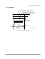
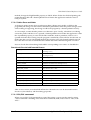
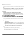
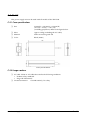
1.5.2.2 Printable Area
Cutting position (manual cutter) (Type A, B)
Cutting position (autocutter) (Type A, B)
Cutting position (manual cutter) (Type D)
34.9
27
22.1
(6.8)
63.4
(5.8)
Maximum 200dots,
400 positions
[Units: mm]
76
Printable area for 76mm width paper
Rev. B
General Information 1-11
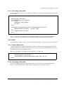
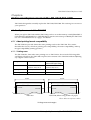
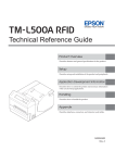
Cutting position (manual cutter) (Type B)
Cutting position (autocutter) (Type B)
Cutting position (manual cutter) (Type D)
34.9
27
22.1
(6.7)
57
(5.8)
Maximum 180 dots,
360 positions
[Units: mm]
69.5
Printable area for 69.5mm width paper
1-12 General Information
Rev. B
TM-U220 Technical Reference Guide
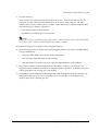
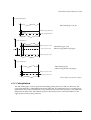
Cutting position (manual cutter) (Type B)
Cutting position (autocutter) (Type B)
Cutting position (manual cutter) (Type D)
34.9
27
22.1
(4.2)
(5.8)
47.5
Maximum 150 dots,
300 positions
[Units: mm]
57.5
Printable area for 57.5mm width paper
1.6 Other Specifications
1.6.1 EMI and Safety Standards Applied
1.6.1.1 Printer (TM-U220)
EMC is Tested Using the EPSON’s AC adapter.
Europe:
North America:
Japan:
Oceania:
Rev. B
CE Marking Directive 89/336/EEC
EN55022 Class B
EN55024
IEC 61000-4-2
IEC 61000-4-3
IEC 61000-4-4
IEC 61000-4-5
IEC 61000-4-6
IEC 61000-4-11
Safety: EN 60950
EMI: FCC/ICES-003 Class A
Safety: UL60950/CSA C22.2 No. 60950
EMI: VCCI Class A
EMC: AS/NZS 3548 Class B
General Information 1-13
1.6.1.2 AC Adapter C (packaged in ANK model)
Europe:
CE Marking Directive 89/336/EEC
EN55022 Class B
EN55024
IEC 61000-4-2
IEC 61000-4-3
IEC 61000-4-4
IEC 61000-4-5
IEC 61000-4-6
IEC 61000-4-11
EN61000-3-2
EN61000-3-3
Safety: EN 60950
North America:
Safety: UL1950/CSA C22.2 No. 950
Japan:
Electrical Appliance and Material Control Law
Oceania:
Safety: AS3260
1.6.1.3 AC adapter (packaged in Multilingual model (PS-180))
Europe:
CE Marking Directive 89/336/EEC EN55022 Class B
EN55024
IEC61000-4-2
IEC61000-4-3
IEC61000-4-4
IEC61000-4-5
IEC61000-4-6
IEC61000-4-11
Safety Standard: EN60950
North America:
EMI: FCC Class A
Safety Standards: UL1950-2TH-D3
C-UL
Japan:
EMI: VCCI Class 1
Safety Standards: Electrical Appliance and Material Control
Law of Japan.
This unit meets EMI and EMC Standards, whether or not it is connected to an EPSON product.
1-14 General Information
Rev. B
TM-U220 Technical Reference Guide
1.6.2 Reliability
Life:
Mechanism: 7,500,000 lines
MTBF:
180,000 hours
Failure is defined as a Random Failure occurring at the time
of the Random Failure Period.
MCBF:
18,000,000 lines
This is an average failure interval based on failures relating to
Wearout and Random Failures up to the life of 7.5 million
lines.
Print head life:
150 million characters (using an average of 2 dots/wire per
character). (The printing pattern is EPSON test pattern).
Autocutter life:
800,000 cuts
End of life is defined as the point at which the printer reaches
the beginning of the wearout period.
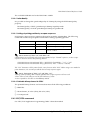
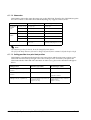
1.6.3 Environmental Conditions
Temperature:
During operation: 0 °C to 50 °C {41°F to 122 °F}.
(At 34 °C {93°F} or higher, there are humidity restrictions as
listed below. )
Humidity:
During operation:10 to 90% (no condensation)
During storage:10 to 90% (no condensation; excludes paper
and ribbon)
Operating temperature and humidity range
Rev. B
General Information 1-15
Vibration resistance:
When packed:
Frequency: 5 to 55 Hz
Acceleration: 19.6m/s2 {2 G}
Sweep: 10 minutes (half cycle)
Duration: 1 hour
Directions: x, y, and z
No external or internal damage should be found after the
vibration test, and the unit should operate normally.
Impact resistance:
When packed:
Package: EPSON standard package
Height: 60 cm (2 feet)
Directions: 1 corner, 3 edges, and 6 surfaces
No external or internal damage should be found after the
drop test, and the unit should operate normally.
When unpacked:
Height: 5 cm (2")
Directions: Lift one edge and release it (for all 4 edges).
When the printer is not printing, no external or internal
damage should be found after the drop test.
1.6.4 Installation
Install the printer horizontally as a basic position.The printer also must be installed so that it
does not move or vibrate during paper cutting or the drawer kick-out operation. Velcro tape is
available as an option.
The printer (Type B or D) can be also installed on a wall with the optional wall hanging bracket
(WH-10) . (The schedule is TBD.)
1-16 General Information
Rev. B
TM-U220 Technical Reference Guide
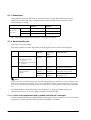
1.7 External Dimensions and Mass
1.7.1 External Dimensions and Mass
Model type
External Dimensions
Mass
Width
Height
Depth
Type A
160 mm
{Approximately 6.3"}
157.5 mm
{Approximately 6.2"}
286 mm
{Approximately 11.3"}
Approximately 2.7 kg
{5.9 lb}
Type B
160 mm
{Approximately 6.3"}
138.5 mm
{Approximately 5.5"}
248 mm
{Approximately 9.8"}
Approximately 2.5 kg
{5.5 lb}
Type D
160 mm
{Approximately 6.3"}
138.5 mm
{Approximately 5.5"}
248 mm
{Approximately 9.8"}
Approximately 2.5 kg
{5.1 lb}
(All the numeric values are typical.)
Color:EPSON standard color (ECW, EDG)
1.7.1.1 Overview (Type A)
Rev. B
General Information 1-17
1.7.1.2 Overview (Type B)
1-18 General Information
Rev. B
TM-U220 Technical Reference Guide
1.7.1.3 Overview (Type D)
Rev. B
General Information 1-19
1-20 General Information
Rev. B
TM-U220 Technical Reference Guide
Chapter 2
System Planning
This section provides you information for system planning.
2.1 Control Method
A TM printer can print and be controlled using any of the following three methods:
1. Windows printer driver (EPSON Advanced Printer Driver)
2. EPSON OPOS ADK
3. ESC/POS commands
Depending on the driver or interface to be used, an IP setting tool for the Ethernet specification,
a USB device driver, and a logo registration utility for printing (TMFlash logo utility) are
provided.
See “How to Get a Driver” in this chapter.
2.1.1 Windows Driver (EPSON Advanced Printer Driver)
The EPSON Advanced Printer Driver is a method for controlling the TM printer in the same
manner as the Windows standard printer driver.
2.1.1.1 General Features of the EPSON Advanced Printer Driver
The EPSON Advanced Printer Driver has the following features:
❏ Supplies the Windows printer driver for the TM printer, which enables printing through
general Windows applications.
❏ Enables executing unique functions of the POS printer, such as paper cutting and drawer
opening.
❏ Font type selection enables printing with the printer’s internal fonts.
❏ Enables obtaining the printer status by StatusAPI with a programming language such as
VisualBasic. This makes it possible to have bi-directional communication with the TM
printer under the Windows standard printer driver environment.
Note:
The statusAPI is the API for controlling the printer, which is supplied exclusively by EPSON. Using this
enables obtaining printer status and transmitting ESC/POS commands.
Rev. B
System Planning 2-1
2.1.1.2 EPSON Advanced Printer Driver Components
Installer recognizes PC environment in which the installation will be done and installs DLL files
and software components necessary for operating automatically. Driver, sample program, or
manual can be selected to be installed.
❏ Driver
You can select a driver depending on the purpose of usage (installation can be done at the same
time). Each has functions such as two-color printing, smoothing, continuous printing, and
option selection for cutting method.
•
Receipt: printing receipt
•
Reduce35: reducing whole print display to fit it into the width of receipt paper and
printing it
❏ Sample program
Sample program for using the StatusAPI with Visual Basic and Visual C++ can be installed.
❏ Manual
The following manuals can be installed:
•
Driver: User’s Manual
•
Status API: Reference Manual
2.1.1.3 EPSON Advanced Printer Driver Support Environment
❏ Supported interfaces
•
Serial, Parallel, USB, Ethernet
❏ Supported Operating Systems: Epson has confirmed performance with the following:
•
Windows 95 English Version Standard OSR2.5
•
Windows 98 English Version Second Edition
•
Windows NT Ver 4.0 English Version SP5, SP6
•
Windows 2000 English Version
•
Windows XP English Version
❏ Supported Development Languages
•
Visual Basic
•
VisualC++
2-2 System Planning
Rev. B
TM-U220 Technical Reference Guide
❏ Supported devices
(For detailed information on which devices can be used, see the release note for the driver.)
•
EPSON receipt printer
•
EPSON customer display
•
EPSON cash drawer
Note:
The USB specification printer needs the USB driver and the Ethernet specification printer needs the IP
setting utility in addition.
For detailed information, please contact your dealer or EPSON.
2.1.2 EPSON OPOS ADK
EPSON OPOS ADK supports the development environment necessary for OLE for Retail POS
(OPOS) application development by OPOS Control proposed by the OPOS committee and
supplies a printer driver (OCX) conforming to OPOS.
When developing an OPOS confirmed application, use the following control methods. EPSON
OPOS ADK has the following features.
❏ EPSON OPOS ADK supports not only the OPOS Control (CO + SO) proposed by the OPOS
committee but also totally supports the OPOS application development environment such
as utilities for installation and setup, the contents necessary for development, such as sample
programs and manuals, and also the function of Log when debugging, and silent
installation, which enables easy installation for a targeted PC.
❏ EPSON OPOS ADK supports DirectIO with parameters for unique functions exclusively for
TM printers by EPSON. Also the power notice function, offline buffer clear processing, and
device irregular processing that has been taken into account by developers are supported by
the driver; these can reduce the number of application steps.
Note:
For detailed information for the API functions, refer to “OLE for Retail POS Application Programmer’s
Guide (APG)” issued by the OPOS committee.
2.1.2.1 General Features of EPSON OPOS ADK (OPOS Control)
OPOS Control included in EPSON OPOS ADK has the following features:
❏ Offers CO for each device class and SO for EPSON devices.
❏ Can use Direct IO with parameter
Rev. B
•
Acquires maintenance counter
•
Prints bit image for which NVRAM has already been registered
System Planning 2-3
❏ Power on notice function (recovering automatically to the status before the power is turned
off when turning on the power again)
❏ Offline buffer clear processing (deleting contents in print buffer at offline)
❏ Debugging function (trace function)
•
Logs between an application and CO (for used API and its return value)
•
Logs for device status (acquires causes for offline and errors in devices)
2.1.2.2 EPSON OPOS ADK Contents
Any installer later than EPSON OPOS ADK Ver2.10 supports the silent install function that can
install the OPOS environment without a user interface, which offers easier installation. With this
installer, OPOS Control for EPSON devices that are compatible with OPOS, manuals, utilities
and sample programs described below can be installed.
❏ OPOS Control for EPSON devices
The following can be installed: CO, SO, header file for C++, header file for VB, TLB file for
CO, or device information file.
❏ Manuals
•
User’s Guide (Environment construction manual: installation/uninstallation/usage of
each utility)
•
Application Development Guide (for OPOS compatible application developers: editions
for common description and for each device)
❏ Utilities
•
SetUpPOS Utility
Can select a device to be used, connection port and settings, such as paper width,
monochrome/two-color (only for two-color supported devices) and print waiting time.
•
TM Flash logo utility
Can register a bit map file to the printer and customer display.
•
USB device driver
Required to connect a USB specification printer.
•
Sample program
Sample programs in VB and VC++ can be installed.
2-4 System Planning
Rev. B
TM-U220 Technical Reference Guide
2.1.2.3 EPSON OPOS ADK Supported Environment
❏ Supported interfaces
•
Serial, Parallel, USB, Ethernet
❏ Supported Operating Systems: Epson has confirmed performance with the following:
•
Windows 95 English Version Standard OSR2.5
•
Windows 98 English Version Second Edition
•
Windows NT Ver 4.0 English Version SP5, SP6
•
Windows 2000 English Version
•
Windows XP English Version
❏ Supported Development Languages
•
Visual Basic
•
VisualC++
2.1.3 ESC/POS Command
Print/control by ESC/POS commands is direct control for TM printers using the ESC/POS
commands proposed by EPSON. Sending ESC/POS commands to the printer from an
application enables direct control of the printer. For the detailed information regarding the
ESC/POS commands, contact the dealer where you purchased the product.
Note:
USB specification printer needs the USB driver and the Ethernet specification printer needs the IP
setting utility in addition.
For detailed information, see item 4.1.4 Driver Information and Download Site in this Chapter.
2.1.4 How to Get a Driver
Please contact EPSON or your dealer about OPOS, APD, and ESC/POS.
Rev. B
System Planning 2-5
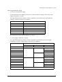
2.2 Connection Form and Cables
2.3 Serial Connection
When the TM printer is connected to the host PC with a serial interface, the following connection
forms are possible:
•
Stand alone
•
Y-connection
•
Pass-through connection
Connections for usable serial cross cables are as follows:
The type of cable that should be used depends on the operation and the handshake method for
the TM printer. You can operate the TM printer by Windows driver, OPOS, or ESC/POS
commands. XON/XOFF, DTR/DSR, or RTS/CTS are available as handshake controls. See tables
in following sections for the type cable for each connection.
2-6 System Planning
Rev. B
TM-U220 Technical Reference Guide
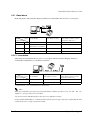
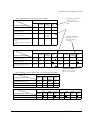
2.3.1 Stand alone
Both TM printer and customer display (DM-D) are connected to the host PC via serial port.
2
1
Application XON/XOFF
TM side
control
control setting
(except OPOS)
DTR/DSR
(DOS, OPOS, Visual C)
RTS/CTS
(DOS, Windows driver, Visual C,
Visual Basic, MSComm)
XON/XOFF
1
Type A or B
—
—
2
DM-D500: A,B
Other DM-D: not available
—
—
1
—
Type A or B
Type B
2
—
Type A or B
Type B
DTR/DSR
2.3.2 Y-connection
TM printer is connected to the host PC via serial port and the customer display (DM-D) is
connected to TM printer via a modular connector.
Application
XON/XOFF
(except OPOS)
DTR/DSR
(DOS, OPOS, Visual C)
RTS/CTS
(DOS, Windows driver, Visual C,
Visual Basic, MSComm)
XON/XOFF
Not available
—
—
DTR/DSR
—
Type B (*)
Type B
TM side
control
control setting
(*) When RTS/CTS control is used between the TM and DM.
Note:
When you would like to provide power from TM-U220 to a DM-D, you have to use “PS-180.“ The “AC
Adapter C” can’t provide power to a DM-D.
You need to use the UB-S09 interface when you use a modular connector.
On the DM-D (DM-D500 etc...) which has DIP switch to select Y-type connection, confirm that the DIP
switch has been set “Y-type connection: Enable.”
Rev. B
System Planning 2-7
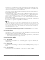
2.3.3 Pass-through connections
The TM printer is connected to the customer display (DM-D) via a serial port, and the DM-D is
connected to the host PC via a serial port.
Note:
On the DM-D (DM-D500 etc...) which has a DIP switch to select Y-type connection, confirm that the
DIP switch has been set to “Y-type connection: Disable.”
Application XON/XOFF
TM side
control
control setting
(except OPOS)
DTR/DSR
(DOS, OPOS, Visual C)
RTS/CTS
(DOS, Windows driver, Visual C,
Visual Basic, MSComm)
XON/XOFF
Not available
—
—
1
—
Type A or B
Type B
2
—
Type A or B
Type A or B
DTR/DSR
2.4 Parallel Connection
The TM printer is connected to the host PC via a parallel interface board (UB-P02II). The
customer display (DM-D) is connected to the host PC via a serial port.
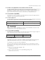
2.5 USB connection
The TM printer can be connected to the host PC via a USB connector, and other TM printers can
be connected to the first printer via USB. (See “Changing the DIP Switch Settings” in Chapter 3
for DIP switch settings.)
2-8 System Planning
Rev. B
TM-U220 Technical Reference Guide
Modular
(with UB-U02II)
(with UB-U01II)
Self-powered USB HUB
(with UB-U01II)
Note:
UB-U01II has bus-powered USB HUB. Therefore This USB model printer can’t be connected directly to
other bus powered HUB (including other UB-U01II equipped TM printer) and bus-powered function
whose current consumption is over 100mA. If you would like to connect other USB model TM printer
with UB-U01II, use a self powered USB HUB as shown in the above figure.
When you would like to provide power from TM-U220 to a DM-D, you have to use “PS-180.“ The “AC
Adapter C” can’t provide power to a DM-D.
The host PC needs to have an installed “USB device driver” for using USB model TM printer. Please
contact EPSON or your dealer about the USB device driver and the procedure for installing.
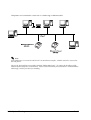
2.6 Ethernet connection
Rev. B
System Planning 2-9
TM printers are connected to a network via a hub using an Ethernet cable.
Note:
If the TM printer is connected to the host PC via an Ethernet interface, a DM-D cannot be connected to
the TM printer.
We provide the IP address setup utility“EPSON TMNet WinConfig,” for setting the IP address of the
Ethernet model TM printer on the host PC. Please contact EPSON or your dealer about “EPSON TMNet
WinConfig” and the procedure for installing.
2-10 System Planning
Rev. B
TM-U220 Technical Reference Guide
Chapter 3
Setup
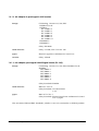
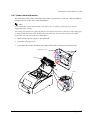
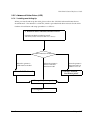
3.1 Part Name and Basic Operation
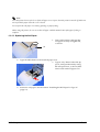
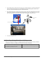
3.1.1 Part name
unit (Type A only)
roll paper cover
ribbon casette cover
power switch
control panel
This figure is Type A.
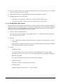
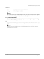
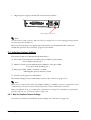
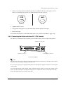
3.1.1.1 Connectors
WARNING:
Do not connect a telephone line to the drawer kick-out connector or the display module connector;
otherwise the printer and the telephone line may be damaged.
Rev. B
Setup 3-1
You can connect up to four cables to the printer. They all connect to the connector panel (on the
bottom rear of the printer), which is shown below.
FG
FG
interface
connector
drawer kick-out
connector
DK
DC24V
power supply
connector
Note:
This illustration shows the serial interface model. The other interface connector looks slightly different.
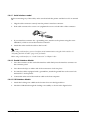
3.1.2 The Control Panel
The control panel is shown below.
❏ POWER LED
❏ ERROR LED
❏ PAPER OUT LED
❏ FEED button
3.1.2.1 LED
POWER
On:
Power supply is stable.
Off:
Power supply is not stable.
ERROR
When this light is on but not blinking, it means that the printer is offline. Check to see if a cover
is open. When this light is blinking, there is an error. See “LED Blinking Pattern” in Chapter 4.
3-2 Setup
Rev. B
TM-U220 Technical Reference Guide
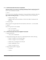
PAPER OUT
On:
The roll paper near end (*1) or real end is detected.
Off:
Paper is loaded (normal condition).
Flashing:
Self-test waiting state for test print.
Note:
The roll paper near-end sensor is available as an factory option. If the printer is not equipped with the roll paper
near-end sensor, the roll paper near-end is always detected as paper present. See “Adjusting Position of Roll
Paper Near End Detector” (page 3-26) for information on adjusting the detector.
3.1.2.2 Control Panel Buttons
The control panel has paper button that you may have to use, although most paper handling
functions will be handled by your software.
FEED
Use this button to feed roll paper or to start a roll paper self test. (See “Self Test Procedure” (page
3-39).)
Note:
The FEED button can be disabled by using an ESC/POS command. Refer to “ESC/POS Application
Programming Guide” for details.
Rev. B
Setup 3-3
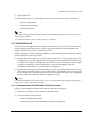
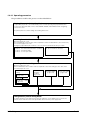
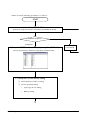
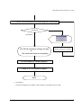
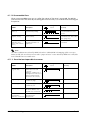
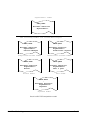
3.2 Setup Flow
You have to set up your printer to use it. And you can adjust some features by customizing
them. This section describes the setup.
The set up flow of preparing to use printer is below.
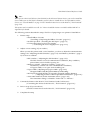
1. Printer set up
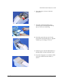
❏ Install Ribbon Cassette
❏ Install Paper Roll
❏ Connect the Printer to the Power Supply
(See “Printer setup,” page 3-6)
2. Adjust various settings (If you need to)
❏ DIP switches
❏ Memory switches
❏ Paper width
(Adjust the spacer & Memory switches)
❏ Roll Paper Near End Detector
(For equipped model only)
❏ Auto cutter method (Type A, B)
(See “Adjusting Various Settings” (page 3-
3. Connect the Printer to the host PC/POS terminal
(See “Install a Printer Driver in the Host PC / POS Terminal” (page 3-33))
When you select
Direct control
method (ESC/
POS command,)
you don’t need
to install any
drivers.
4. Driver setup
❏ OPOS
❏ APD
(See “Install a Printer Driver in the Host PC /
POS Terminal,” page 3-33)
5. Complete set up
3-4 Setup
Rev. B
TM-U220 Technical Reference Guide
Note:
When you use OPOS (OCX driver from EPSON) or the Advanced Printer Driver, you need to install the
driver. When you use ESC/POS commands, you don’t have to install drivers. For information on these
drivers, see “Control Method” on page 2-1 and “Install a Printer Driver in the Host PC / POS Terminal”
(page 3-33).
This printer can be installed on a wall. See “How to Install the Printer on a Wall with the WH-10” in
Appendix B for details.
The following sections describe the setup. The flow of preparing to use printer is listed below.
1. Printer setup
• Install Ribbon Cassette
(“Installing or Replacing the Ribbon Cassette” (page 3-6))
• Install Paper Roll (“Installing the Roll Paper” (page 3-7))
• Connect the Pritner to the Power Supply
(“Connecting the Power Supply Unit” (page 3-13))
2. Adjust various setting ( If you need to)
When you use this printer with a serial interface, you have to adjust the communication
settings. See “Adjusting the DIP Switches” (page 3-15) and “Memory Switches” (page 318) for how to set them.
• DIP switches (“Adjusting the DIP Switches” (page 3-15))
The DIP switches set serial communication conditions, busy condition,
print column, receive buffer capacity, etc...
• Memory switches (“Memory Switches” (page 3-18))
The Memory switches set serial communication conditions,
roll paper width, cover open status handling, etc...
• Paper width (“Adjusting Roll paper width” (page 3-25))
The paper width is set by the spacer & Memory switch setting.
• Roll Paper Near End Detector (For model equipped with the detector)
(“Adjusting Position of Roll Paper Near End Detector” (page 3-26))
• Auto cutter method (“Select Autocutter action” (page 3-27))
The Autocutter setting is selectable “Partial cut“ or “Full cut.“
3. Connect the Pritner to the Host PC/POS Terminal (and Cash Drawer)
(“Connecting the Printer to the Host PC / POS Terminal” (page 3-29))
4. Driver set up (If you use driver)
(“Install a Printer Driver in the Host PC / POS Terminal” (page 3-33))
5. Complete the setup
Rev. B
Setup 3-5
3.3 Printer setup
3.3.1 Installing or Replacing the Ribbon Cassette
EPSON recommends the use of genuine EPSON ribbon cassettes. Ribbon cassettes not
manufactured by EPSON may cause damage to your printer that is not covered by EPSON’s
warranties.
To install the ribbon cassette for the first time or to replace a used ribbon, follow the steps below:
1. Unpack the ribbon cassette and turn
the knob in the direction shown to
take up any slack.
Knob
2. Open the ribbon cassette cover of the
printer, using the tabs on each side of
the cover.
Tab
3. Remove the old ribbon, if there is
one.
4. Insert the new ribbon cassette as
shown and push the ribbon cassette
down until it clicks.
Note:
Make sure the ribbon is installed between the
print head and the platen without wrinkles or
creases.
5. Close the ribbon cassette cover of the printer.
3-6 Setup
Rev. B
TM-U220 Technical Reference Guide
3.3.2 Installing the Roll Paper
The installing procedure is little different between Type A and Type B, D.
CAUTION:
Be sure to use roll paper that meets the specifications.
Be sure not to touch the manual cutter. Otherwise your fingers might be injured.
Rev. B
Setup 3-7
3.3.2.1 Installing rhe Roll Paper for Type B, D
1. Using scissors, cut the leading edge of
the roll paper, as shown in the left figure.
2. Turn on the printer and open the roll
paper cover by using the tab, as shown in
the left.
Tab
3. Insert the roll paper, as shown on the left.
Note:
Note the direction the paper comes off the
roll, as shown below.
When using 2-ply roll paper, be sure that the
top and bottom sheets are aligned at the paper
exit. See the below illustration.
4. Close the roll paper cover.
3-8 Setup
Rev. B
TM-U220 Technical Reference Guide
3.3.2.2 Installing the Roll Paper for Type A
1. Using scissors, cut the leading edge of
the roll paper, as shown in the left figure.
Tab
2. Turn on the printer and open the roll
paper cover by using the tab, as shown in
the left.
Note:
The printer feeds for 30 mm automatically if
the roll paper cover is open. This is a normal
operation to prevent the printer from
damaging the paper when the roll paper cover
is opened or closed.
Since the printer does not feed even if the roll
paper cover is open when the printer is
turned off, make sure not to pinch the paper
when the cover is closed.
3. Open the unit by using the lever, as
shown in the left.
lever
Rev. B
Setup 3-9
4. Insert the roll paper, as shown in the left.
Note:
Note the direction the paper comes off the
roll, as shown in following
When using 2-ply roll paper, be sure that the top
and bottom sheets are aligned at the paper exit.
See below illustration.
5. Close the roll paper cover.
6. If you are not using a take-up spool, pull out a small amount of roll paper and close
the roll paper cover; then tear off the paper with the manual cutter. You can skip
steps 6 through 11.
7. When using 2-ply roll paper, pull out the
roll paper to the bottom front of the
printer as a guide, as shown in left.
3-10 Setup
Rev. B
TM-U220 Technical Reference Guide
8. Close the unit, as shown in the left
illustration.
9. Insert the end of the bottom paper
(journal paper) into the paper take-up
spool, as shown in following.
10. Insert the paper take-up spool in the
printer. Be sure that the paper is aligned
with the spool's flange, as shown.
11. Feed the paper with the FEED button so
that the paper is taken up by the spool.
12. Close the roll paper cover and tear off the
roll paper with the manual cutter, as
shown.
Rev. B
Setup 3-11
Note:
Since the printer does not feed even if the roll paper cover is open when the printer is turned off, make sure
not to pinch the paper when the cover is closed.
Do not open the roll paper cover during printing or paper feeding.
When using the printer, be sure to cut the roll paper with the manual cutter after paper feeding is
complete.
3.3.2.3 Replacing the Roll Paper
1. Turn on the printer and open the
roll paper cover by using the tab,
as shown.
Tab
2. Types B and D: Remove the used roll paper core.
3. Type A only: Remove the take-up
spool, and open the unit by using
the unit open lever, as shown; then
remove the used roll paper core.
4. Insert new roll paper. See the section “Installing the Roll Paper for Type A”
(page 3-9).
3-12 Setup
Rev. B
TM-U220 Technical Reference Guide
3.3.3 Connecting the Power Supply Unit
Use the power supply or equivalent for your printer as listed below.
TM-U220 Alphanumeric model (Type A,B, D)
TM-U220 Multilingual model (Type A,B, D)
AC Adapter C (which is packed with ANK model)
or PS-180 (Which is provided as option)
PS-180 (which is packed with Multilingual model)
Note:
The AC Adapter packed in the carton box of ANK model cannot be used for the Multilingual model.
The "AC adapter, C," which is packed with the alphanumeric model, cannot be used with the
multilingual* model. Be sure to use the "PS-180" with the multilingual* model. If the “AC adapter, C,”
packed with the alphanumeric model, is connected to the multilingual* model by mistake, the printer
might not operate correctly. For example, printing might stop before all the lines are printed or the printer
might print the same line repeatedly.
*Multilingual means the printer model that can print any one of the following: Japanese Kanji, Simplified
Chinese, Traditional Chinese, Thai characters, or Korean characters.
WARNING:
Make sure you use the AC Adapter C or EPSON PS-180 power supply or equivalent.
Don’t use the PA-#### or PB-#### power supply unit with TM-U220.
Using an incorrect power supply may cause fire or electrical shock.
CAUTION:
When connecting or disconnecting the power supply from the printer, make sure the
power supply is not plugged into an electrical outlet. Otherwise you may damage the
power supply or the printer.
3.3.3.1 Connecting procedure
1. Make sure the printer’s power switch is turned off and the power supply’s power cord is
unplugged from the electrical outlet.
2. Check the label on the power supply to make sure the voltage required by the power supply
matches that of your electrical outlet.
Rev. B
Setup 3-13
3. Plug the power supply cord into the connector shown below.
FG
FG
DK
DC24V
Power supply connector
Note:
To remove the DC cable connector, make sure the power supply’s power cord is unplugged; then grasp the
connector and pull it straight out.
When you connect the power supply unit to the printer, we recommend to do a self test to
confirm the operation. See “Self Test” (page 3-39) for details.
3.4 Adjusting Various Settings
This printer is able to be adjusted for the items below:
❏ DIP switch (communication condition, busy condition, print column,
receive buffer capacity, etc...)
❏ Memory switch (serial communication conditions, roll paper width,
cover open status handling, etc...)
❏ Roll paper width (76mm / 69.5mm / 59.5mm)
Adjusting the spacer & memory switch
❏ Position of roll paper near end detector
The current settings can be confirmed by a self test. (See “Self Test” (page 3-39).)
Note:
When you use serial interface model with 1200bps, 2400bps, or 19200bps, you have to adjust DIP switch
“Serial interface selection“ function and Memory switch “Serial communication condition“.
When you adjust the items, we recommend to confirm the new setting. The confirmation is performed by
running a self-test. See “Self Test Procedure” (page 3-39).
3.4.1 How to Confirm Current Settings
You can use a self-test to confirm the current settings. See “Self Test” on page 3-39.
3-14 Setup
Rev. B
TM-U220 Technical Reference Guide
3.4.2 Adjusting the DIP Switches
The printer has two sets of DIP switches. The function of the DIP switches is different for each
interface model.
If you need to change settings, follow the steps below to make your changes:
CAUTION:
Turn off the power while removing the DIP switch cover to prevent an electric short,
which can damage the printer.
Use a crosshead screwdriver to remove the screw holding the DIP switch cover.
Look at the numbers and letters in the area
indicated in the illustration. If the last
letters are “US”, use the “US” tables below.
If the last letters are “STD”, use the “STD”
tables.
ON
OFF
ON
CAUTION:
OFF
Be sure to put back the DIP switch
cover before using the printer.
Note:
The functions of the switches are shown in the following sections.
The DIP switch function of US is little different from the STD.
3.4.2.1 When the letters are STD
Serial model
(DIP Switch 1)
(DIP Switch 2)
SW Function
On
Off
SW Function
On
Off
1
Data receive error
Ignored
Prints “?”
1
Print column
42/35
40/33
2
Receive buffer
capacity
40 bytes
4 KB
2
Reserved
(Auto cutter enable/
disable)
Type A, B
Fixed to On
Type D
Fixed to Off
3
Handshaking
XON/XOFF
DTR/DSR
3
Reserved
-
Fixed to Off
4
Word length
7 bits
8 bits
4
Serial interface
selection
Memory
switch
DIP switch
5
Parity check
Yes
No
5
Reserved
-
Fixed to Off
6
Parity selection
Even
Odd
6
Reserved
-
Fixed to Off
7
Transmission speed
4800 bps
9600 bps
7
Pin 6 reset signal
Used
Not used
8
BUSY condition
Receive
buffer full
Receive
buffer full or
Offline
8
Pin 25 reset signal
Used
Not used
Rev. B
Setup 3-15
Parallel / USB / Ethernet model (Except serial)
(DIP Switch 1)
(DIP Switch 2)
SW
Function
On
Off
SW Function
On
Off
1
Auto line feed
Enabled
Disabled
1
Print column selection
42/35
40/33
2
Receive buffer
capacity
40 bytes
4 KB
2
Reserved
(Auto cutter enable/
disable)
Type A, B
Fixed to On
Type D
Fixed to Off
3~7
Reserved
-
Fixed to Off
3~7 Reserved
-
Fixed to Off
8
BUSY condition
Receive
buffer full
Receive
buffer full or
Offline
8
Used
Not used
Pin 31 reset signal
Note:
See the next page for “When the letters are US.”
See “Notes for DIP switch 2-1” (page 3-18) about the DIP SW 2-1 setting.
When you use serial interface model with 1200bps, 2400bps, or 19200bps, you have to adjust DIP switch
“Serial interface selection“ function and Memory switch “Serial communication condition“.
3-16 Setup
Rev. B
TM-U220 Technical Reference Guide
3.4.2.2 When the letters are US
Serial model
(DIP Switch 1)
SW Function
On
(DIP Switch 2)
Off
SW Function
On
Off
1
Data receive error
Ignored
Prints “?”
1
Print column
42/35
40/33
2
Receive buffer
capacity
40 bytes
4 KB
2
Reserved
(Auto cutter enable/
disable)
Type A, B
Fixed to On
Type D
Fixed to Off
3
Handshaking
XON/XOFF
DTR/DSR
3
Pin 6 reset signal
Used
Not used
4
Word length
7 bits
8 bits
4
Pin 25 reset signal
Used
Not used
5
Parity check
Yes
No
5
Reserved
-
Fixed to Off
6
Parity selection
Even
Odd
6
Reserved
-
Fixed to Off
7
Transmission speed
4800 bps
9600 bps
7
Reserved
-
Fixed to Off
8
BUSY condition
Receive
buffer full
Receive
buffer full
or Offline
8
Serial interface
selection
Memory
switch
DIP switch
Parallel / USB / Ethernet model (Except serial)
(DIP Switch 1)
(DIP Switch 2)
SW
Function
On
Off
SW
Function
1
Auto line feed
Enabled
Disabled
1
Print column selection 42/35
On
40/33
Off
2
Receive buffer
capacity
40 bytes
4 KB
2
Reserved
(Auto cutter enable/
disable)
Type A, B
Fixed to On
Type D
Fixed to Off
3
Reserved
-
Fixed to Off
3
Reserved
-
Fixed to Off
4~7
Reserved
-
Fixed to Off
4
Pin 31 reset signal
Used
Not used
8
BUSY condition
Receive
buffer full
Receive
buffer full
or Offline
5~8
Reserved
-
Fixed to Off
Note:
See the previous page for “When the letters are STD.”
See “Notes for DIP switch 2-1” (page 3-18) about the DIP SW 2-1 setting.
When you use serial interface model with 1200bps, 2400bps, or 19200bps, you have to adjust DIP switch
“Serial interface selection“ function and Memory switch “Serial communication condition“.
Rev. B
Setup 3-17
3.4.2.3 Notes for DIP switch 2-1
The DIP switch 2-1 defines the print columns as listed in the following table.
DIP switch 2-1 status
Paper width
Character font
ON
OFF
76 mm
Font A (9 x 9)
35
33
Font B (7 x 9)
42
40
Font A (9 x 9)
32
30
Font B (7 x 9)
40
36
Font A (9 x 9)
27
25
Font B (7 x 9)
33
30
69.5 mm
57.5 mm
Unit: cpl (Character per line)
Note:
The cpl of a Kanji character font is available to be changed by an ESC/POS command. (default: 22 cpl to
25cpl)
3.4.3 Memory Switches
This printer has “Memory switch“ set which is software switches. Memory switch set has “Msw
2,” “Msw 8,” “Customize value,” “Serial communication condition.”
“Memory switch setting utility” can change the Memory switch set to ON or OFF as shown in
the table below (default: all OFF):
Note:
The Memory switch is available to be changed by five methods:
• Memory switch setting utility
• Memory switch setup mode (there are limitations on what can be changed)
• Control from setupPOS (OPOS only, and there are limitations on what can be changed)
• Control from Windows driver (Advanced Printer Driver only, and
there are limitations on what can be changed)
• Control from ESC/POS command
Some Memory switch settings can be changed by the “Memory switch setting mode.“See “Memory
Switch Setup Mode” on page 3-20.
Settings of the memory switch are stored in the NV memory; therefore, even if the printer is turned off, the
settings are maintained. Excessive use of this function may destroy the NV memory. As a guideline, do
not use this function more than 10 times a day.
When you use OPOS or APD, generally you don’t need to adjust memory switch because OPOS or APD
are able to set these items automatically.
When you replace a TM-U210 with a TM-U220, you should adjust the Msw 8-5 to OFF.
3-18 Setup
Rev. B
TM-U220 Technical Reference Guide
Memory Switch 2
SW
Function
On
Off
1
Reserved
-
Fixed to Off
2
Reserved
-
Fixed to Off
3
Selection of the character code system of GB2312
the Simplified Chinese
4 ~ 8 Reserved
-
GB18030
Fixed to Off
Note:
Msw 2-3:
The memory switch Msw 2-3 affects the Simplified Chinese model only.
Memory Switch 8
SW
Function
1 ~ 4 Reserved
On
Off
-
Fixed to Off
5
Selection of the cover open status
Cover open
Paper end
6
Reserved
-
Fixed to Off
7
Condition to release the BUSY in the
receive buffer
Remaining 138 bytes
Remaining 256 bytes
8
Printer cover open during operation
Errors that can possibly
recover
Errors that automatically
recover
Note:
Msw 8-5:
When Off is selected, a bit of the "roll paper end sensor" in each status that is transmitted from the printer
is changed every time the roll paper cover is open or closed. When On is selected, a bit of the "roll paper
cover open / close" in each status that is transmitted from the printer is changed every time the roll paper
cover is open or closed. When you replace a TM-U210 with a TM-U220, you should adjust the Msw 8-5
to Off.
Msw 8-8:
When Off is selected, a bit of the "automatic recoverable error" in each status that is transmitted from the
printer is changed every time the roll paper cover is open. When On is selected, a bit of the "mechanical
error" in each status that is transmitted from the printer is changed every time the roll paper cover is open.
The setting of Msw 8-5 and 8-8 can be set by “Memory switch setup mode.“ See “Memory Switch Setup
Mode” on page 3-20.
Customize value
Function
Roll paper width
Rev. B
Selectable value
57.5 mm
69.5 mm
76 mm (default value)
--
Setup 3-19
Note:
These setting can be set by “Memory switch setup mode.“ See “Memory Switch Setup Mode” on page 320.
See “Adjusting Roll paper width” (page 3-25) also to adjust roll paper width.
Serial communication
Function
baud rate
Selectable value
1200 bps
2400 bps
4800 bps
9600 bps
19200 bps
--
Parity
None
Odd
Even
--
Handshake
DSR/DTR
XON/XOFF
Data length
7 bit
8 bit
Note:
There are two methods, DIP switch and Memory switch, to adjust the serial communication conditions.
DIP SW2 selects which is effective, DIP switch or Memory switch.
To enable the “Serial communication“ setting, you have to adjust the “Serial interface selection“ function
of DIP switch 2 to “Memory switch.“
These settings can be set by “Memory switch setup mode.“ See “Memory Switch Setup Mode” on page 320.
3.4.4 Memory Switch Setup Mode
The following items are specified in the memory switch setup mode:
❏ Basic Serial communication condition (Serial communication)
•
Transmission speed
•
Parity
•
Handshaking
•
Data length
❏ Receive buffer full release condition (Msw 8-7)
❏ Roll paper width (Customize value)
❏ Cover open status (Msw 8-5)
Note:
All new settings will be lost if the power supply is turned off in the memory switch setup mode. Be sure to
follow the proper procedure, and turn the power off at the correct time.
3-20 Setup
Rev. B
TM-U220 Technical Reference Guide
3.4.4.1 Starting the memory switch setup mode
Use the following procedure to start the memory switch setup mode.
1. Open the roll paper cover.
2. Turn the power on while pressing the paper FEED button.
3. Press the FEED button twice while POWER, ERROR, and PAPER OUT LEDs are lit.
4. Close the cover. The printer prints the enabled settings of the memory switches and
instructions.
5. Follow the instructions to process the switch setup.
Note:
In the memory switch setup, the paper out LED may be flashing. The flashing time indicates “The times of
FEED button is pressed before the roll paper cover is closed.“
3.4.4.2 Ending memory switch setting mode
Once the setting is performed, the contents of the setting are stored. Then the printer initializes.
When initialization is finished, the printer returns to normal operating mode.
Rev. B
Setup 3-21
3.4.4.3 Operating procedure
The procedures used for this process are described below.
Entering Memory Switch Setting Mode
1. Open the paper roll cover and turn the power on while pressing the paper FEED button.
2. Press the paper FEED button twice while POWER, ERROR, and PAPER OUT LED are lighting.
3. Close the cover.
The printer prints the current settings and setting instructions.
Selecting Items to Set
Open the paper roll cover.
Press the FEED button the number of times required to select the desired item (as shown below);
then close the paper roll cover.
Pressing the paper FEED button 0 times or 10 or more times will terminate this procedure.
❒ 3 times:
❒ 4 times:
❒ 7 times:
❒ 9 times:
Basic Serial Interface Settings
Receive buffer full release condition
Roll Paper Width
Cover open status
❒ 0, 1, 2, 5, 6, 8 times: Unused
❒ 10 or more times: Unused
Selecting Individual Settings
Open the paper roll cover.
Press the FEED button the number of times required to select the setting for each item; then
close the paper roll cover.
Basic Serial Interface
Setting
Baud Rate Setup
(page 3-23)
Receive buffer
full release
condition
(page 3-24)
Roll Paper Width
(page 3-24)
Cover open status
(page 3-24)
Data Length,
Handshake, or Parity
(page 3-23)
Ending Memory Switch Setting Mode
The printer prints the new settings and saves the settings to non-volatility memory. Then, the
software resets and enters the normal printable status. Turn the power supply OFF.
3-22 Setup
Rev. B
TM-U220 Technical Reference Guide
Selecting individual settings
❏ Basic serial interface setting
To select transmission conditions, first choose “Serial interface settings”; then select “Data
length, handshake, or parity.”
Press the FEED button the number of times required to select the desired “Serial interface
settings” used for transmission conditions.
Press FEED button
Setting selected
0 ~ 3 times:
No change
4 times:
19200 bps
5 times:
9600 bps
6 times:
4800 bps
7 times:
2400 bps
8 times:
1200 bps
9 or more times:
No change
bps: Indicates the number of transmitted bits per second (bps).
❏ Data length, handshake, or parity
Press the FEED button the number of times required to select the desired “Data length,
handshake, or parity” setting used for transmission conditions.
Press FEED button
Setting selected
Data Length
0 times:
No change
1 time:
8 bits
Handshake
Parity
DTR/DSR control
No parity
2 times:
Even
3 times:
Odd
4 times:
XON/XOFF control
No parity
5 times:
Even
6 times:
Odd
7 times:
7 bits
DTR/DSR control
No parity
8 times:
Even
9 times:
Odd
10 times:
XON/XOFF control
No parity
11 times:
Even
12 times:
Odd
13 or more times:
Rev. B
No change
Setup 3-23
❏ Receive buffer full release condition
Press the FEED button the number of times required to select the desired receive buffer full
release condition setting.
Press FEED button
Receive buffer full release condition
0 times:
No change
1 time:
256 bytes remain (Msw 8-7: Off)
2 times:
138 bytes remain (Msw 8-7: On)
3 or more times:
No change
❏ Paper width setting
Press the FEED button the number of times required to select the desired roll paper width setting
(Customize value.)
Press FEED button
Selecting paper width
0 times:
No change
1 time:
76 mm
2 times:
69.5 mm
3 times:
58.5 mm
4 or more times:
No change
Note:
See “Adjusting Roll paper width” (page 3-25) also to adjust roll paper width.
❏ Cover open status
Press the FEED button the number of times required to select the desired the mapping of cover
open status setting.
Press FEED button
Setting selected
0 times:
No change
1 time:
Paper out (Msw 8-8: OFF)
2 times:
Cover open (Msw 8-8: ON)
3 or more times:
No change
3-24 Setup
Rev. B
TM-U220 Technical Reference Guide
3.4.5 Adjusting Roll paper width
The TM-U220 accommodates 76 mm {3"},69.5 mm {2.74"}, 57.5 mm {2.26"} wide paper rolls.
Note:
When you use a near-end detector equipped model, be sure not to pinch the lead wires of the near-end
detector between the roll paper guide and the roll paper holder, and to push the lead wires inside so that the
lead wire of the paper-end detector does not contact the motor gear.
When replacing the wires, be sure that the wires do not catch between the roll paper guide and the roll
paper holder.
leading the wires
between the holder
and frame
Roll paper guide
Roll paper holder
1. Make sure the power supply is disconnected.
2. Open the roll paper cover.
3. Take off the roll paper guide from the printer by loosening the two screws.
A: paper width76 mm
B: paper width69.5mm
C:paper width57.5mm
Roll paper
guide
A
position of fixing
the screws (left
side)
B
C
position of fixing the
screws (right side)
4. Push the roll paper guide on the appropriate width (See figure above.)
Rev. B
Setup 3-25
5. Tighten the spacer with two screws included with the guide. (See figure above.)
6. Set the memory switch (customize value) for the paper width. (See “Memory Switches”
(page 3-18))
3.4.6 Adjusting Position of Roll Paper Near End Detector
Below are two reasons for the roll paper to require an NE detector adjustment.
❏ To adjust the location of detection for the diameter of the roll paper core.
❏ To adjust the amount of remaining paper.
The procedure is as following.
1. Make sure the power supply is disconnected.
2. Open the roll paper cover, and remove the paper roll.
3. Loosen the detector adjustment screw with a coin or similar tool.
4. Adjust the detector by sliding the lever in the direction shown below.
Knob
Detector
adjustment screw
#1 setting
Detector lever
#2 setting
Seeing at outside for roll paper spacer
The table below shows the point at which the near-end detector is triggered. Note that this
figure is a calculated value, and there may be some variations, depending on the printer.
Detection point of roll paper near-end
Detector position (attaching point of
the detector adjustment lever )
Trigger point (included the thickness of paper roll core)
#1 setting
Approx. 8 mm
#2 setting
Approx. 5 mm
5. Tighten the detector adjustment screw.
6. Check to be sure that the detecting lever moves freely.
3-26 Setup
Rev. B
TM-U220 Technical Reference Guide
3.4.7 Select Autocutter action
The autocutter action on the TM-U220 can be either “partial cut“ or “full cut.“ The procedure to
change from one to the other is described below.
Note:
It is recommended to feed approximately 2.116 mm or more in advance of printing to prevent dot
displacement after cutting.
The cutting type (partial cut or full cut) must be selected before the printer is first used. If the cutting type
is changed from partial cut to full cut after the printer has been used, the printer may not be reliable
because the wear-out level of the cutter blade differs.
1. Make sure the power supply is disconnected.
2. Open the roll paper cover.
3. Push and take out the shaft from the inside of the Frame, and release the three hooks.
Roll paper cover
Hook
Frame
Shaft
Rev. B
Setup 3-27
4. Loosen the screw as indicated in following figure.
Remove the screw
Loosen the screw
Emergency cutter
5. Lift the top of the cutter unit upward towards you and remove from the dowel.
dowel
Cutter unit
3-28 Setup
Rev. B
TM-U220 Technical Reference Guide
6. When you select partial cut (default), you have to adjust the dowel to the right, as shown.
When you select full cut, you have to adjust the dowel to left as shown.
Partial cut
Full cut
7. Tighten the two screws.
8. Set again the roll paper cover, and set the shaft which is taken out in step 3.
9. Install roll paper
10. Execute the self test to confirm the cutter action. (See “Self Test Procedure” (page 3-39))
3.4.8 Connecting the Printer to the Host PC / POS Terminal
All cables are connected to the connector panel located on the lower rear side of the printer.
Drawer kick connector
FG
FG
Interface connector
DK
DC24V
Power supply connector
Connector panel
Note:
The figure above shows the connector panel for the serial interface model printer. The shape of the interface
connector varies according to the type of interface used.
Be sure to turn off the power supply for both the printer and the host computer unit before connecting the
various cables.
You need an appropriate serial, parallel, USB, or Ethernet interface cable to connect your computer to the
printer. For the serial model, it is important that you use a null modem cable, not any other serial cable,
and for the parallel model use an IEEE 1284 cable.
Rev. B
Setup 3-29
3.4.8.1 Serial Interface model
Before connecting any of the cables, make sure that both the printer and the host PC are turned
off.
1. Plug the cable connector securely into the printer’s interface connector.
2. If the cable connector has screws on it, tighten the screws on both sides of the connector.
3. If your interface connector has a grounding wire, attach it to the printer using the screw
labeled FG, which is next to the interface connector.
4. Attach the other end of the cable to the host PC.
Note:
When using serial interface, you need to adjust serial communication using the DIP switches. See
“Adjusting the DIP Switches” (page 3-15) for details.
When using serial interface, see “Serial Connection” in Chapter 2 also.
3.4.8.2 Parallel Interface Models
1. Press the connector on the end of the interface cable firmly into the interface connector on
the connector panel.
2. Press down the clips on either side of the connector to lock it in place.
3. For interface cables equipped with a ground line, attach the ground line to the screw hole
marked "FG" on the printer.
4. Connect the other end of the interface cable to the host computer.
3.4.8.3 USB Interface Models
1. Attach the locking wire saddle at the location shown in the figure below.
2. Hook the USB cable through the locking wire saddle, as shown in the figure below.
3-30 Setup
Rev. B
TM-U220 Technical Reference Guide
Note:
Hooking the USB cable through the locking wire saddle, as shown in the figure below, will prevent the
cable from coming unplugged.
USB upstream connector
UB-BOARD
Locking wire saddle
USB cable
USB downstream connector
(Only for the USB HUB: UB-U01)
DM connector
Attaching locking wire saddle
3. Connect the USB cable from the host computer to the USB upstream connector.
4. For models that have the UB-U01II installed, a maximum of two USB devices can be
connected to the USB downstream connector.
Note:
The UB-U01 serves as a bus power-supply hub. Therefore, it is important to note that bus power
supply hubs (including the UB-U01II) and bus power supply functions with power dissipation of 100
mA or more cannot be connected directly to the printer. (A UB-U02II can be directly connected to a
UB-U01 hub.)
5. Install the UB-U01II/02II device driver on the host computer.
Note:
For information on how to obtain the required device drivers and their installation procedures, contact
the nearest EPSON service center.
Rev. B
Setup 3-31
3.4.8.4 Ethernet interface
The following view shows the part names of the UB-E01.
10BASE-T Ethernet
interface
connector
LED (green) LED (red)
Switch
Be sure not to push the
LEDs by accident
If you press and hold
this switch when the
printer is on, the
interface will be
reset to the factory
settings
Before connecting any of the cables, make sure that both the printer and the host computer are
turned off.
1. Make sure both the printer and the host computer are turned off.
2. Plug the 10BASE-T cable connector securely into the UB-E01's 10BASE-T Ethernet connector
until you feel it click.
CAUTION:
Do not connect a telephone line , a display module cable, or a drawer kick-out cable
to the UB-E01’s 10BASE-T connector.
Note:
The display module connector on the TM printer cannot be used when the UB-E01 is installed.
3. Connect the power supply to the printer.
3-32 Setup
Rev. B
TM-U220 Technical Reference Guide
3.4.8.5 Connecting a Drawer
CAUTION:
Be sure to connect a drawer that meets printer specifications. Connecting a drawer of
the wrong specifications may result in damage to both the drawer and the printer.
Never connect the telephone line to the drawer kick out connector (labeled “DK”).
Doing so may result in damage to both the telephone line and the printer.
Never connect the drawer cable to the customer display connector (labeled “DM-D”).
Doing so may result in damage to both the drawer cable and the printer.
1. Connect the drawer cable to the drawer kick out connector (labeled “DK”) on the connector
panel.
FG
FG
DK
DC24V
Drawer kick connector
Connecting drawer
2. The connecting is finished.
3.5 Install a Printer Driver in the Host PC / POS Terminal
EPSON provides printer drivers for the TM-U220. The drivers are OPOS and Advanced Printer
Driver (APD). They are for the Windows environment.
3.5.1 OPOS
3.5.1.1 Install and Set up.
When you install and set up, please refer to the User's Manual, the file is automatically created at
the installation of OPOS ADK.
Rev. B
Setup 3-33
Outline of install and Setup procedure is as follows.
START
1. Installation OPOS ADK
(Execute the Setup.exe in DISK1, and continue to installation by wizard)
Is installation completed?
ERROR
Completed
2. Setup the OPOS & device setting by using SetupPOS utility
For detail refer to
[ User Manual]
You can setup the OPOS and device setting by the SetupPOS utility.
2.1 Setup the OPOS & device setting
❏ Select the device and I/F setting
❏ Device specified setting
3-34 Setup
•
Paper type & size setting
•
Bitmap setting
Rev. B
TM-U220 Technical Reference Guide
2.2. Device communication test by executing the CheckHealth
ResultCode
ERROR
SUCCESS
The OPOS and device settings are right.
&
The Install and Setup are completed.
Confirm the error condition by
referring to the [User's manual]
(3. Confirmation by sample program)
4. Make a OPOS compliant program
END
1. Installation.
Execute the Setup.exe in DISK1. and continue to installation by wizard.
Rev. B
Setup 3-35
2. Set up the device and environment.
1. Set the device setting by using SetupPOS utility.
•
•
Select the device and I/F setting.
Device specified setting. (set the specified setting of the device)
2. Execute the CheckHealth
Device communication test.
•
•
If you get "SUCCESS", the setting of the device is right.
If you get ResultCode (error), please re-check the device connection setting by
following the User's Manual.
After performing the above procedure, please use an OPOS compliant program in your system.
Note:
Please refer to the sample program when you make a program.
OPOS ADK provides a sample program for each device class. The sample programs are intended as
programs to serve as references for application developers. The ways to use the principal methods and
properties for each device are introduced in the form of Visual Basic, Visual C++ programs. In this
manual, it is introduced in the form of Visual Basic.
3.5.1.2 Package contents of EPSON OPOS ADK.
Package contents of EPSON OPOS ADK are same as that of the previous one.
❏ Installer
❏ SetupPOS Utility
❏ OPOS Controls
❏ Manual
•
User’s Manual :Installation of the EPSON OPOS ADK, Configurations,and explanations
of the attached tools.
•
ADG : Detailed information on the each device to support the development.
ADG for General :
General information on the development.
ADG for Common Information :
Common information to all the devices.
ADG for device class :
General information on the device class.
ADG for model :
Specific explanation on the device.
Sample program :
Information on the Sample Programs.
❏ Sample Program
Sample program for VB and VC (for each device class)
3-36 Setup
Rev. B
TM-U220 Technical Reference Guide
3.5.2 Advanced Printer Driver (APD)
3.5.2.1 Installing and Setting Up
When you install and set up the APD, please refer to the “EPSON Advanced Printer Driver
Install Manual.“ The Manual is a PDF file, which is provided with other manuals for the APD.
Outline of installation and setup procedure is as follows.
1. Install EPSON Advanced Printer Driver
Select the modules needed to install:
TM-U220, Status API (and USB device driver)
What interface model?
When the printer is
Serial or Parallel
interface model
When the printer is
USB interface model
2. Install “USB driver”
When the printer is
Ethernet model on
Window 98 or 95
3. Install “EPSON
Net Direct print”
4. Set up the printer port
5. Test print
Rev. B
Setup 3-37
1. Install EPSON Advanced Printer Driver
Execute the installer “ADT###e.exe,“ and select modules which you need. The
recommended modules are shown below. Refer to the installation manual for details.
EPSON TM-U220 Receipt
(76mm):
This module (printer driver) is required for printing on
76mm width receipt.
EPSON TM-U220 Receipt
(69.5mm):
This module (printer driver) is required for printing on
69.5mm width receipt.
EPSON TM-U220 Receipt:
(57.5mm)
This module (printer driver) is required for printing on
57.5mm width receipt.
Status API:
This module is required for monitoring the printer. This
module provides API to monitor the printer’s status.
USB driver:
This module (device driver) is required for the USB
interface model printer.
Note:
For the Manual, Sample program, and each utility, you have to download separately the
ADT###e.exe.
2. Install “USB driver”
When you use a USB interface model printer, you need to install the “USB driver.” The
procedure depends on the OS; therefore see the installation manual. If you aren’t using a
USB interface model printer, you don’t need to install this module.
3. Install “EPSON Net Direct print“
When you use the Ethernet interface model printer with Windows98/95, you need to install
“EPSON Net Direct print.” See the installation manual for details. If you aren’t using the
Ethernet interface model printer, or aren’t using Windows 98/95, you don’t need to install
this module.
4. Set up the printer port
After installing APD (and “USB driver” or “EPSON Net Direct print“) you need to adjust the
printer port setting for the printer interface model. See the Installation manual and the
User’s manual for details.
Note:
When you use the serial interface model printer, you need to adjust serial communication setting
between printer and printer driver. See “Adjusting the DIP Switches” (page 3-15) and “Memory
Switches” (page 3-18) for information on the settings.
5. Test print
Execute test print from the “property” of printer to confirm the setting. If the test print is not
correct, please see the “Notes” on the “User’s Manual” and “Status API Reference Manual”
to solve the your problem.
3-38 Setup
Rev. B
TM-U220 Technical Reference Guide
Note:
You can use the printer with sample program (written in Microsoft Visual Basic, Visual C++). The
sample program is provided separately.
3.6 Self Test
The self test lets you know if your printer is operating properly. It checks the control circuits,
printer mechanisms, print quality, control software version, and DIP switch settings.
This test is independent of any other equipment or software, so it is a good idea to run it when
you first set up the printer and if you have any trouble. If the self tests work correctly, the
problem is in the other equipment or the software, not the printer.
3.6.1 Self Test Procedure
1. Make sure the printer is turned off and the roll paper cover is closed properly.
2. While holding down the FEED button, turn on the printer using the switch on the front of the
printer. The self test prints the printer settings and then prints the following, cuts the paper,
and pauses. (The PAPER OUT light blinks.)
If you want to continue SELF-TEST printing, Please press the
FEED button.
3. Press the FEED button to continue printing. The printer prints a pattern using the built-in
character set.
4. The self test automatically ends and cuts the paper after printing the following:
*** completed ***
The printer is ready to receive data as soon as it completes the self test.
Note:
If you want to pause the self test manually, press the FEED button. Press the FEED button again to
continue the self test.
Rev. B
Setup 3-39
3-40 Setup
Rev. B
TM-U220 Technical Reference Guide
Chapter 4
Troubleshooting
This section describes general troubleshooting.
4.1 LED Blinking Pattern
4.1.1 Error Types
The printer stops all printer operations for the selected paper section, goes offline, and the
ERROR LED blinks when an error is detected.
4.1.1.1 Errors that automatically recover
ERROR LED Blinking Pattern
160 ms
ERROR
Description
Recovery
Roll paper cover
open error (when
recoverable error is
selected) (*1)
The roll paper cover is
opened when printing.
Recovers automatically
when the cover is
closed.
Print head
temperature error (*2)
The temperature of the
print head is extremely
high
Recovers automatically
when the print head
cools
Note:
(*1) This conditions are selected by MSW 8-5, 8-8. When MSW 8-5 (mapping of the cover open status) is
off, the error hasn’t occurred but there is a “paper end error” instead. If MSW 8-8 is off, this error is
handled as an automatically recoverable error.
(* 2) Print head temperature error is not abnormal.
Rev. B
Troubleshooting 4-1
4.1.1.2 Recoverable Errors
When a recoverable error occurs, after the cause of the error is removed, the printer
can recover from the error by receiving an error recovery command without turning off
the power:
ERROR LED Blinking Pattern
160 ms
ERROR
Description
Recovery
Paper roll cover open
error (*1)
The roll paper cover is
opend when printing.
Recovers by error recovery
command with the cover
closed
Autocutter error
(Type A, B only)
The autocutter does not
work correctly
Recovers by error recovery
command. (See “Autocutter
Jam” (page 4-3))
Home position
detection error
(This is “Mechanical
error“)
The home position cannot
be detected due to a
paper jam
Recovers by error recovery
command
Note:
(*1) These conditions are selected by MSW 8-5 and 8-8. When MSW 8-5 (mapping of the cover open
status) is OFF, the error does not occur and a “paper end error” occurs instead. If MSW 8-8 is ON, this
error is handled as a recoverable error.
4.1.1.3 Errors that are impossible to recover:
ERROR LED Blinking Pattern
160 ms
ERROR
Description
R/W error in memory
or gate array
After R/W checking, the
printer does not work
correctly.
Writing to, reading out, or
erasing the NV memory for
image scanning results
does not work correctly.
Impossible to recover
High voltage error
The power supply voltage
is extremely high
Impossible to recover
Low voltage error
The power supply voltage
is extremely low
Impossible to recover
CPU execution error
The CPU executes an
incorrect address or I/F
board is not connected
Impossible to recover
Print head
temperature
detection circuit error
There is an abnormality in
the print head
temperature
Impossible to recover
4-2 Troubleshooting
Recovery
Rev. B
TM-U220 Technical Reference Guide
4.2 Removing a Paper Jam
CAUTION:
Be sure not to touch the manual cutter. Otherwise your finger might be injured.
1. Turn the power off.
2. Open the roll paper cover by using the tab, as shown in the below illustration.
3. If you have a Type A printer, remove the take-up spool and open the unit by using the unit
open lever, as shown in the illustration.
Roll paper cover
Tab
lever
1. open the roll paper cover
2. (only type A) open the unit
4. Remove the jammed paper.
Note:
When you turn the power off by mistake during the printing operation, the cutter blade may stop in the
paper feed line. So the paper may not be fed in the first operation normally when you turn the power on. If
the phenomenon happens again after removing the jammed paper, try the solution “Autocutter Jam”
(page 4-3).
4.3 Autocutter Jam
If a foreign object such as a push pin or paper clip drops in the autocutter and causes the auto
cutter to lock up, the printer enters an error state and begins the recovery operation
automatically.
If the problem is not serious, the autocutter returns to its normal position without any
intervention by the user.
If the autocutter does not return to its normal position by itself, follow the steps below to fix the
problem:
1. Open the roll paper cover, and remove the jammed object if there is one.
Rev. B
Troubleshooting 4-3
2. Turn off the printer, and close the roll paper cover, and turn it back on. Then the cutter blade
returns to the normal position. If you would like not to turn off the printer, send an error
recovery command and initialize printer command instead.
3. If the cutter blade doesn’t return to the normal position, return the cutter blade to the normal
position by rotating the autocutter knob in the direction of the arrow. When it is returned to
the normal position, a lever comes into the center of hole in the autocutter frame.
Hole
Lever
Cutter cover
Autocutter unit
Knob
4. Close the roll paper cover.
4.4 Printer Stops Printing / Printer Repeats Printing on a Line
When you connect the wrong power supply unit, printer will not perform correctly. See below
to determine which power supply unit should be connected to the printer.
TM-U220 Alphanumeric model (Type A,B, D)
TM-U220 Multilingual model (Type A,B, D)
AC Adapter C (which is packed with ANK model)
or PS-180 (Which is provided as an option)
PS-180 (which is packed with the Multilingual model)
4-4 Troubleshooting
Rev. B
TM-U220 Technical Reference Guide
Note:
*Multilingual means the printer model that can print any one of the following: Japanese Kanji, Simplified
Chinese, Traditional Chinese, Thai characters, or Korean characters.
Use the self test to confirm what model of printer you have, and then use the correct power supply. (See
“Self Test Procedure” (page 3-39) for how to run the self test.)
Rev. B
Troubleshooting 4-5
Alphanumeric model
...
SELF-TEST
Resident Character
Alphanumeric
The following models are called Multilingual
SELF-TEST
...
...
SELF-TEST
Resident Character
Alphanumeric
Traditional Chinese
Resident Character
Alphanumeric
Chinese GB18030
Simplified Chinese model
Traditional Chinese model
SELF-TEST
...
...
SELF-TEST
Resident Character
Alphanumeric
Thai 3 pass
Resident Character
Alphanumeric
Korean
Thai model
Korean model
...
SELF-TEST
Resident Character
Alphanumeric
Japanese
Japanese model
Result of SELF-TEST and printer model
4-6 Troubleshooting
Rev. B
TM-U220 Technical Reference Guide
4.5 Printer prints “?“ or Incorrect Data With Serial Interface
If one of the following errors occurs during serial interface communication, the printer prints “?”
or ignores the data, depending on the setting of DIP switch 1-1.
❏ Parity error
❏ Framing error
❏ Overrun error
Note:
For other errors, we recommend confirming the transmission setting of DIP switch 1-3: Handshaking.
4.6 Print Speed is Slow When Using Windows Printer Driver
When the printer prints a Windows font using the EPSON Advanced Printer Driver, the print
speed is slow. To improve the print speed, use a printer font.
4.7 Hexadecimal Dump mode
This feature allows experienced users to see exactly what data is coming to the printer. This can
be useful in finding software problems. When you turn on the hex dump function, the printer
prints all commands and other data in hexadecimal format, along with a guide section to help
you find specific commands.
To use the hex dump feature, follow these steps:
1. After you make sure the printer is off, open the paper roll cover.
2. While you hold down the FEED button, turn on the printer.
3. Close the cover.
4. Run any software program that sends data to the printer. The printer prints “Hexadecimal
Dump” and then all the codes it receives in a two-column format. The first column contains
the hexadecimal codes and the second column gives the ASCII characters that correspond to
the codes. Part of a hexadecimal dump is shown below:
Hexadecimal Dump
To terminate hexadecimal dump,
press FEED button three times.
Rev. B
Troubleshooting 4-7
1B 21 00 1B 26 02 40 40
. ! . . & . @ @
1B 25 01 1B 63 34 00 1B
. % . . c 4 . .
41 42 43 44 45 46 47 48
A B C D E F G H
•
A period (.) is printed for each code that has no ASCII equivalent.
•
In hex dump mode all commands except real time ESC/POS commands are disabled.
5. Open the cover to set the printer offline so that it will print the last line.
6. Close the cover and turn off the printer, press the FEED button three times, or reset the
printer to turn off the hex dump mode.
Note:
The hexadecimal dump mode can’t be used with OPOS or the APD.
4-8 Troubleshooting
Rev. B
TM-U220 Technical Reference Guide
Chapter 5
Application Development Information
This section contains usable information to develop POS systems that use this printer.
5.1 Various Status Categories
This printer is able to send various status reports to the host PC. This section describes about the
kind of statuses and handling.
Status Categories
Description
Drawer kick connector pin
status
Cash drawer is open or closed.
Roll Paper cover status
Roll paper cover is open or closed
Paper feeding button status
Paper feed button is pressed or not
Error status
Various error information (Off-line / On-line), (detail of the error;
Mechanical error, autocutter error, auto-recovery error,
unrecoverable error)
Paper remaining amount
status
It provides status of paper remaining amount (Near-end or Paper
end)
Note
Near-end status (paper remain status) is supported only by printers equipped with a near-end
detector. The near-end detector is a factory option.
This printer has an Automatic status back (ASB) function that automatically transmits changes in
printer status. It is available in any control method (APD, OPOS, ESC/POS command.)
The status format depends on each control method. Refer to each manual for detail.
The statuses are useful for the following situations.
❏ When an error status is sent to the host PC, the host PC can display an error message or
solution message for operator.
❏ When “Paper near end” or “Paper end“ status is sent to the host PC, the host PC can display
a warning message for operator to replace roll paper.
5.1.1 Printer Status on APD
When you use APD to get printer’s status, you have to install “Status API“ and use it. Refer to
“Status API User’s Manual“ and the sample program of Status API for details.
Rev. B
Application Development Information 5-1
5.1.2 OPOS
Note
This section describes the summary of status handling. Refer to “OPOS ADK Application Development
Guide General Functions” for details.
5.1.2.1 Checking the printer state
The state of the printer can be checked through properties supported by the printer. For
example, if the user wants to check if the printer cover is open, the CoverOpen property can be
used.
If OPOSPOSPrinter1.CoverOpen = True Then
MsgBox ìCover is open!î
End If
This and many other events can also be checked by firing a StatusUpdateEvent.
[Event management]
Private Sub OPOSPOSPrinter1_StatusUpdateEvent(ByVal Data As Long)
If Data = PTR_SUE_COVER_OPEN Then
MsgBox ìCover is open!î
End If
End Sub
StatusUpdateEvent can return information on the following items.
STATUS INFORMATION
PTR_SUE_COVER_OPEN
Cover is open.
PTR_SUE_COVER_OK
Cover is closed.
PTR_SUE_REC_EMPTY
Receipt paper is out.
PTR_SUE_REC_NEAREMPTY
Receipt paper is near the end. (The near end detector is
factory option. When the printer does not have one, the status
does not occur.)
PTR_SUE_REC_PAPEROK
Receipt paper is OK.
PTR_SUE_IDLE
Printer State is idle.
When the FlagWhenIdle property is set to TRUE, PTR_SUE_IDLE is sent to inform the
application that the printer is idle. Other than when data is being sent, the printer is in an idle
state, so if FlagWhenIdle is TRUE, an event will be fired when printing is finished. After the
event is fired, FlagWhenIdle will be set to FALSE. By using this value, the information below can
be found out.
*Finding out when multiple asynchronous print jobs have finished printing. When multiple
asynchronous print jobs have been sent to the printer, it is possible to know when they have
finished printing. After setting the AsyncMode property to TRUE and running the PrintNormal
5-2 Application Development Information
Rev. B
TM-U220 Technical Reference Guide
method, change the FlagWhenIdle property to TRUE. When all data has finished printing, the
printer becomes idle and a StatusUpdateEvent is fired to the application with the value of
PTR_SUE_IDLE.
5.1.2.2 Printer Errors and Status
A change in printer status when asynchronous data is being sent is made available to the
program by the firing of an ErrorEvent and StatusUpdateEvent. When the printer changes status
while nothing is happening, the change is told to the program by a StatusUpdateEvent only.
As an example, assume that the printer cover becomes open. Usually, when data is not being
sent to the printer and the cover is opened, a StatusUpdateEvent is fired to the application. After
the AsyncMode property is set to TRUE and a method is used to print data, if the cover is
opened while the data is being sent, the program is notified by an ErrorEvent. ErrorEvents are
fired when the error has interrupted the data that is being sent. Only StatusUpdateEvent will
fire when the error does not effect the data and the data will continue being sent as normal.
Reasons for the ErrorEvent being fired and the corresponding error names are listed below.
ResultCode/ ResultCodeExtended Reason
OPOS_E_ILLEGAL
There is an abnormality with the device. (Includes the
following 1 error)
OPOS_E_EXTENDED
Error determined by the device’s SO (Includes the
following 4 errors)
OPOS_EPTR_COVER_OPEN
Cover is open.
OPOS_EPTR_REC_EMPTY
Receipt paper is empty.
OPOS_E_FAILURE
Hard error (Includes the following 6 errors).
OPOS_EPTR_UNRECOVERABLE
Error that cannot be recovered from.
OPOS_EPTR_CUTTER
Error with the auto cutter.
OPOS_EPTR_MECHANICAL
Mechanical error.
OPOS_EPTR_OVERHEAT
Head overheat error.
OPOS_EX_DEVBUSY
Device busy error.
OPOS_EPTR_REC_CARTRIDGE_REMOVED
Receipt cartridge is removed.
OPOS_EPTR_REC_CARTRIDGE_EMPTY
Receipt cartridge is empty.
OPOS_EPTR_REC_HEAD_CLEANING
Receipt head starts cleaning.
After an error occurs, more detailed information about the error can be obtained from the
ErrorLevel, ErrorStation, and ErrorString properties.
5.1.2.3 ESC/POS commands
When you use ESC/POS commands to control the printer, you can get the status by using
“status command” including Auto Status Back command (ASB.) Please refer to “ESC/POS
APG.”
Rev. B
Application Development Information 5-3
5.2 Cash Drawer Control
5.2.1 Advanced Printer Driver
5.2.1.1 Drawer Open
When you control a drawer which is connected to this printer using APD, you have 2 methods
to open the drawer. The first method is using “Control font,” second is using “Status API.“
Below is as example of a program (Visual Basic) to open a cash drawer using Control font.
'Execute open cash drawer1.
Printer.Font.Name = "control"
Printer.Print "A"
íThisîAî means ìopen the drawer1 with 50msec pulse.ì
Below is as example of a program (Visual Basic) to open a cash drawer using Status API.
'call api to open the drawer1
rtn = BiOpenDrawer(m_hApi, EPS_BI_DRAWER_1, EPS_BI_PULSE_100)
íThis calling means ìopen the drawer1 with 100msec pulse.ì
Note: Program needs to call “BiOpenMonPrinter“ before calling “BiOpenDraewer.“
5-4 Application Development Information
Rev. B
TM-U220 Technical Reference Guide
5.2.1.2 Checking Drawer Status
You can get drawer status by using Status API. Below is examples of program which checks the
drawer status.
'get the current printer status
rtn = BiGetStatus(m_hApi, getstatus)
If rtn < 0 Then
ErrMsg (rtn) íError handling
Exit Sub
End If
If (getstatus And ASB_DRAWER_KICK) = ASB_DRAWER_KICK Then
MsgBox("Drawer is opened")
íPin No.3 is high
Else
MsgBox("Drawer is closed")
End If
There are the other checking method (Bi BiSetStatusBackFunction, BiSetStatusBackWnd) in
Status API. Refer to the Status API User’s Manual and the sample programs for detail.
5.2.2 OPOS
Programming examples of how to use API function relating to a Cash Drawer are shown below.
5.2.2.1 Drawer Open/Close
Using the OpenDrawer method opens the cash drawer. The DrawerOpened property can be
used to check the current state of the drawer. To pause the program until the drawer is closed,
the WaitForDrawerClose method is used.
Below is as example of a program to open and close a cash drawer.
If Not OPOSCashdrawer1.DrawerOpened Then
OPOSCashdrawer1.OpenDrawer
OPOSCashdrawer1.WaitForDrawerClose 10000, 1000, 100, 100
End If
5.2.2.2 Checking Drawer Status
There are methods other than explained in section 5.2.2.1 that can be used to check drawer
status. A StatusUpdateEvent is fired whenever the drawer is opened or closed.
Rev. B
Application Development Information 5-5
Below are examples of programs that use events to check if the drawer has been opened or
closed.
[Main Program]
Global DrawerFlag As Boolean
If Not OPOSCashdrawer1.DrawerOpened Then
DrawerFlag = True
OPOSCashdrawer1.OpenDrawer
While (DrawerFlag = True)
íThis part uses timer management to check the status of DrawerFlag.
DoEvents
Wend
End If
[Event Management]
Private Sub OPOSCashdrawer1_StatusUpdateEvent(ByVal As Long)
If Data = False Then
DrawerFlag = False
End If
End Sub
5.2.3 ESC/POS
When you drive a cash drawer which is connected to this printer, please refer to “FAQ about
ESC/POS command.“ About “FAQ about ESC/POS command,“ please contact your dealer or
EPSON.
5.3 NV memory
This printer has NV memory (Non-volatile). The data of NV memory remains after you turn off
the power. The NV memory is available in two ways.
1. NV Bit-image
Please refer “NV Bit-image Printing” (page 5-8) for detail of the function.
5-6 Application Development Information
Rev. B
TM-U220 Technical Reference Guide
2. User NV memory
There is free area in the NV memory that the user can use. You can use this free area for
notations, to write other character information, or for many other purposes. The data
remains after you turn off the power. Use ESC/POS commands to read and write this data.
The following are examples of purposes.
•
Date of the printer for maintenance
•
ID definition for developer or POS system
Note
When you use User NV memory area by using OPOS or APD, you have to use “Direct I/O method”
or “Control A font.” Please contact EPSON or your dealer for details.
Note the following when writing to and erasing NV memory.
❏ The following restrictions apply when performing NV memory operations (including data
storage and deletion).
•
The paper FEED button must not be used to feed paper.
•
The real-time command must not be executed.
•
The ASB status will not be sent, even when the ASB function is set to enabled.
❏ The printer sometimes enters the Busy state while data is written to NV memory. It is
important not to send data from the host computer while the printer is in the Busy state, as it
will be incapable of processing any received data.
❏ Frequent use of the functions for defining data to and deleting data from NV memory can
damage the memory. As a rule in using the various commands, avoid writing to NV
memory more than a 10 times per day.
Rev. B
Application Development Information 5-7
5.4 NV Bit-image Printing
This printer has “NV Bit-image“ Function. This function provides printing bit-image (e.g. a shop
logo.) This function is available for any control method (APD, OPOS, ESC/POS command.)
EPSON provides a tool, “TMFLogo” that enables registration of a bitmap image in the NV
memory of an EPSON TM series printer. The bitmap image in the NV memory can be printed
with the printer by using each control method.
NV
Bit-image
Printable Size
Printing method
<width>
Less than paper width.
Store
Store bitmap to NVRAM by TMFLogo utility in device specific
settings on the SetupPOS utility. If you store the bitmap in a
NVRAM, it is not necessary to restore unless the NV memory is
deleted.
<height>
There is a limitation Height length
= NV memory Size / width length
Print
Depends on each control method.
Note
The available NV memory size for the TM-U220 is 128KB.
Example: The NV memory can store 20 graphics data when the file size of a graphic is 6 KB.
5.4.1 Advanced Printer Driver
5.4.1.1 How to print “NV Bit-image“
APD prints a stored “NV Bit-image“ by using “Control font.“ See the User’s Manual of
Advanced Printer Driver for detail.
5.4.1.2 Printable bitmap format in APD
The printable bitmap formats are formats that meet all the following condition.
❏ When using “NV Bit-image“
•
Depends on the TM Flogo utility. (.BMP format)
5.4.2 OPOS
EPSON OPOS ADK provides a tool, “TMFLogo” that enables registration of a bitmap image in
the NVRAM of an EPSON TM series printer. The tool can be used from the device specific
settings of the SetupPOS utility. The bitmap image in the NVRAM can be printed with a printer
by using the DirectIO method. Concerning the available NVRAM size for the TM-U220, refer to
the ADG for TM-U220 in the OPOS ADK.
5.4.2.1 Printing method
Print stored bitmap by DirectIO method.
•
*Command : PTR_DI_PRINT_FLASH_BITMAP
5-8 Application Development Information
Rev. B
TM-U220 Technical Reference Guide
The available NVRAM size for the TM-U220 is 128KB.
5.4.2.2 LetterQuality
It is possible to change the speed and quality of a bitmap by using the XXXLetterQuality
property.
RecLetterQuality = TRUE ‘print Receipt’s bitmap in quality mode.
RecLetterQuality = FALSE ‘print Receipt’s bitmap in speed mode.
5.4.2.3 Setting of printing position by escape sequence
POS Printers support escape sequences that can be treated as printing data. The following
commands are the escape sequence command for setting of printing position.
Name
Data
Remarks
Center
ESC |cA
Aligns following text in the center.
Right justify
ESC |rA
Aligns following text at the right.
Normal
ESC |N
Restores printer characteristics to
normal condition.
Note1: manner of ”ESC |cA” and “ESC |rA”
Characteristics are reset at the end of each print method or by a “Normal” sequence, so these escape
sequences cannot be used in the following manner.
OPOSPOSPrinter1.PrintNormal PTR_S_RECEIPT, Chr(&H1B) + ”|cA” + ”123”
OPOSPOSPrinter1.PrintNormal PTR_S_RECEIPT, “456” + Chr(13) + Chr(10)
The “123” characters will be printed in the center, but not under “456”. When using a new method to
print characters, it is necessary to add the desired escape sequence again.
Note2 : limitation of ”ESC |cA” and “ESC |rA”
*During rotated printing mode (Left90, right90), these escape sequences will not work.
*These will not work if they are not the first character of a line.
*It is not possible to use these on PrintBitmap method.
5.4.2.4 Printable bitmap format in OPOS
The printable bitmap formats are formats that meet all the following conditions.
❏ BMP files
❏ Monochrome, 16-color (4 bit), 256-color (8 bit)
❏ Uncompressed
5.4.3 ESC/POS command
See “ESC/POS Application Programming Guide“ about the method.
Rev. B
Application Development Information 5-9
5.5 Printing for journal used
This printer can print on carbon paper (original + 1 copy.) This is available to use for journal.
When you use this printer “Type A” model, you can take up the copied paper with Auto take-up
unit. If you use this printer “Type B“ model, you can cut each a receipt and the copy at same
time.
A special control isn’t required to use carbon paper; you can treat it as same as normal paper.
However, when you use the Type A model with Auto take-up unit, you have to install carbon
paper with Auto take-up unit. Please refer “Installing the Roll Paper for Type A” (page 3-9).
5.6 FAQ List
The questions shown in the list below begin with “Q” and their replies with “A.”
1. Sentences beginning with “Q” provide information relating to a question or problem.
2. The instructions described in the “A” sentence answer the question or solve the problem.
5.6.1 Q. Drawer kick does not operate properly.
5.6.1.1 A. Drawer specifications differ, depending on the manufacturer and the part
number.
We recommend to use a Drawer that is made by EPSON. These conditions also apply to any
other devices that use the drawer kick-out connector. Any devices that do not satisfy all the
following conditions must not be used.
[Conditions]
•
A load must be provided between drawer kick-out connector pins 4 and 2 or between
pins 4 and 5. (*1)
•
When the drawer open/close signal is used, a switch must be provided between drawer
kick-out connector pins 3 and 6. (*2)
•
The resistance of the load must be 24 W or more, or the input current must be 1 A or less.
(*3)
•
Be sure to use drawer kick-out connector pin 4 (24 V power output) to drive the device.
Never connect any other power supply to the drawer kick-out connector. (*4)
NOTES:
(*1) Operating the printer with incorrectly installed devices voids the warranty.
(*2) Connecting devices other than the drawer open/close switch voids the warranty.
(*3) If a device with a resistance of less than 24 Ω or an input current of over 1 A is used, the resulting overcurrent
may damage the device.
(*4) Connecting a power supply other than that specified voids the warranty.
5-10 Application Development Information
Rev. B
TM-U220 Technical Reference Guide
5.6.2 Q. Unable to print a part of Page 0 in Visual Basic.
Unable to print a part of Page 0 (for example
) in Visual Basic.
5.6.2.1 A. Follow the procedure
When programming with Visual Basic, limitations prevent data from 81h through 9Fh and from
E0h through FEh from being sent as characters. However, you can use the following procedure
to send this data.
Dim Send_ data(0) As Byte
Send_data(0) = &h81 ’1 byte of sending data
MSComm1.Output = Send_data
Rev. B
Application Development Information 5-11
5-12 Application Development Information
Rev. B
TM-U220 Technical Reference Guide
Chapter 6
Notices for Replacement of the TM-U210/TM-U300
TM-U220 is designed to smoothly replace the TM-U210/TM-U300. This section gives answers to
your questions.
6.1 For Replacement of the TM-U210
When you replace TM-U210 with the TM-U220, you have to set the memory switch [MemSW8-5:
OFF (default)] and [MemSW 8-8: OFF (default)] to get the same statas provided by the TM-U210.
See “6.1.6 Provided statuses (6-5 page)” for details.
6.1.1 About printing format compatibility
The TM-U220 can provide almost the same printing result as the TM-U210. This section
describes the reasons, which are printing area compatibility, character compatibility, and top
margin compatibility (cutting position.)
6.1.1.1 Printing area
The TM-U220 has almost the same printing area as TM-U210 as shown in the following table
and figures.Therefore, the TM-U220 can print same contents as the TM-U210 without adjusting
any original control sources.
Printing areaItem
TM-U210 (Type A,B,D)
TM-U220 (Type A,B, D)
(when 76mm paper using)
Print width
63.34mm
(200dots, 400 position)
63.34mm
(200dots,400position)
Left margin
(5.9mm)
6.8mm
Right margin
(6.76mm)
5.8mm
76 mm
76 mm
63.34 mm
63.34 mm
Printable area
Printable area
5.9 mm
6.76 mm
TM-U210
6.8 mm
5.8 mm
TM-U220 (When using 76mm roll paper)
These values are reference values
Printing area and margins
Rev. B
Notices for Replacement of the TM-U210/TM-U300 6-1
6.1.1.2 Characters
TM-U220 has almost the same character spec as the TM-U210. Therefore, the TM-U220 can print
the same contents as the TM-U210 without adjusting any original control sources.
Character spec
TM-U210 (Type A,B,D)
TM-U220 (Type A,B, D)
Character
par line
(CPI)
Font A (9 x 9)
33 (35) cpl
33 (35) cpl
Font B (7 x 9)
40 (42) cpl
40 (42) cpl
Kanji (16 x 16)
25 (22) cpl
25 (22) cpl
Font A (9 x 9)
1.6 x 3.1
1.6 x 3.1
Font B (7 x 9)
1.2 x 3.1
1.2 x 3.1
Kanji (16 x 16)
2.7 x 2.7
2.7 x 2.7
Code page 0 to 8, and
19 to 26
Code page 0 to 8, and 19 to
26 and code page 16, 17, 18
Character
width
Character configuration
Note:
The character per line for Font A, B can be changed by DIP SW2-1.
The cpl for the Kanji character font can be changed by anESC/POS command. (default:22cpl to 25cpl)
6.1.1.3 Cutting position from print start position
TM-U220 has same distance between the auto cut position and the print start position as the
TM-U210. Therefore the top margin is the same as the previous one when you replace the
TM-U210 with the TM-U220 with autocutter. In other cases, please refer the table and figures
below.
Cutting position
TM-U210 (Type A,B,D)
TM-U220 (Type A,B, D)
Autocutting position to print start
position
27mm
27mm
Manual cut position to print start
position
20.2mm
Type D: 22.1mm
TypeA,B: 34.9mm
Cutting method of partial cut
one point left uncut position at
center position.
(Type A, B only)
6-2 Notices for Replacement of the TM-U210/TM-U300
one point left uncut position at
right position.
(Type A, B only)
Rev. B
TM-U220 Technical Reference Guide
Paper feed direction
TM-U210 (Type A, B, D)
Manual cut position line
22.1 mm
Print start position line
Paper feed direction
Manual cut position line
34.9 mm
Auto cut position line
TM-U220 (Type A, B)
(When using 76mm roll paper)
27 mm
Print start position line
Paper feed direction
TM-U220 (Type D)
(When using 76mm roll paper)
Manual cut position line
22.1 mm
Print start position line
These values are reference values
6.1.2 Cutting Method
The TM-U220 (Type A, B) can perform autocutting with partial cut or full cut. However, the
partial cut method is a little different from the TM-U210. The TM-U210 always uses the partial
cut method. The partial cut method is one point left uncut at the center position, so the method is
different from that of the TM-U220 in respect to the uncut position. The TM-U220 leaves the
right position uncut in the partial cut.
Rev. B
Notices for Replacement of the TM-U210/TM-U300 6-3
6.1.3 Dimensions
Some dimensions of the TM-U220 are smaller than those of the TM-U210 except Type D.
Therefore, the TM-U220 Type A and B printers can be installed in the same space as the
TM-U210 Type A and B.
Dimensions
(W x D x H)
(Unit: mm)
TM-U210
TM-U220
Type A
160 x 295 x 160
160 x 286 x 158
Type B
160 x 248 x 150
160 x 248 x 139
Type D
160 x 248 x 133
160 x 248 x 139
See “1.7.1 External Dimensions and Mass (1-17 page)” for details.
6.1.4 Receive buffer size
This topic is for serial model.
The receive buffer size of the TM-U220 can be changed as shown in the following table.
Product
Receive buffer capacity
Condition of
buffer full
Condition of
release full
state
Byte number from buffer full to
release full state
TM-U210
40 bytes (DIP SW1-2 is On)
Buffer space is
16 bytes
Buffer space is
26 bytes
10 bytes
40 bytes (DIP SW1-2 is On)
Buffer space is
16 bytes
Buffer space is
26 bytes
10 bytes
(Regardless of MemSW8-7)
4K bytes
(DIP SW1-2 is Off)
(default)
Buffer space is
128 bytes
Buffer space is
256 bytes
128 bytes
(MemSW8-7:OFF) (default)
Buffer space is
128 bytes
Buffer space is
138 bytes
10 bytes
(MemSW8-7: ON)
(ANK: DIP SW1-2 is Off)
1K bytes
(Multilingual: DIP SW1-2 is Off)
512 bytes
TM-U220
Note:
The receive buffer of TM-U210 may cause lost data at bufferfull state when there is no FIFO setting, or the
FIFO setting is larger than 16 bytes. However, the TM-U220 will have enough remaining receive buffer
space to prevent data loss at bufferfull state when DIP SW1-2 is Off regardless of the setting of MemSW
8-7.
The “Byte number from buffer full to release full state” is larger than TM-U210. It is for
improvement. However, you should pay attention to the following:
6.1.4.1 Effect on the application when condition of buffer full is changed
The time from buffer empty to buffer full becomes longer. However, there are no cases in which
the Host PC watches the time. Therefore, there should be no problem.
6-4 Notices for Replacement of the TM-U210/TM-U300
Rev. B
TM-U220 Technical Reference Guide
6.1.4.2 Effect on the application in the condition of release full state
The time from buffer full to releasing full state becomes longer than for the TM-U210. There is a
possibility that the application gets a time-out. For countermeasure, Memory switch
[MemSW8-7] assigned for selection of buffer-full release condition, 256 bytes (default) of 138
bytes. Therefore when the time-out occurs, set the memory switch [MemSW8-7] on.
6.1.5 Accessories compatibility
TM-U220 can use same consumables as the TM-U210. However, the power supply unit isn’t
compatible. The following sections describe these.
6.1.5.1 Power supply unit
The TM-U220 can’t use the power supply unit of TM-U210 (PA-#### or PB-####.) The TM-U220
can use the power supply units only as described in the following table.
TM-U220 ANK model (Type A,B, D)
TM-U220 Multilingual model (Type A,B, D)
AC Adapter C (which is packed with ANK model)
or PS-180 (Which is provided as option)
PS-180 (which is packed with Multilingual model)
CAUTION:
Don’t use the PA-#### or PB-#### power supply unit with TM-U220. Connection to an
improper power source may cause fire or shock.
6.1.5.2 Consumable compatibility
TM-U220 can use same consumables as the TM-U210 except the carbon roll paper (original + 2
copies. TM-U220 can’t print on carbon roll paper with 2 copies.)
Consumables
TM-U210 (Type A,B,D)
TM-U220 (Type A,B, D)
Ribbon cassette
ERC-38 (B), (P), (B/R)
ERC-38 (B), (P), (B/R)
6.1.6 Provided statuses
TM-U220 has same statuses as TM-U210; in addition, the TM-U220 has the following status
added. About the purpose of these, See “5.1 Various Status Categories (5-1 page).”
❏ Roll paper cover open/close status (and detector)
When you replace the TM-U210 with the TM-U220, you have to set the Memory switch as
described below. These settings make the TM-U220 have almost the same as behavior as the
TM-U210 statuses.
❏ Msw 8-5 “Cover open status mapping“ : OFF
( Default: Paper end status)
❏ Msw 8-8 “Error select when cover is opened during printing“: OFF
(Default: Auto recover error)
Rev. B
Notices for Replacement of the TM-U210/TM-U300 6-5
See the next tables for the behavior.
ASB(Auto Status Back)
notification does not
occur because status did
not change.
6-6 Notices for Replacement of the TM-U210/TM-U300
Rev. B
TM-U220 Technical Reference Guide
The status behavior is as following two tables.
U210
Printer status bit
Off-line
Paperout LED
Waiting
on-line
recovery
Cover
open
1) Paper end occurs.
OFF line
ON
OFF
--
2) Operator opens the cover for
setting a paper roll.
OFF line
ON
OFF
--
3) Operator installed paper roll
then closed cover.
OFF line
OFF
waiting
on-line
recover
--
OFF
--
Operation when paper-end
4) Type B,D: Operator pressed
FEED SW when paper out LED
blinks.
Type A: After approx.500msec.
passed.
This printer doesn’t have
cover open sensor.
Therefore, there are no
status.
On line
OFF
ASB(Auto Status Back)
notification occurs
because status is
changed.
U220 (Msw 8-5: OFF)
Printer status bit
U220 (Msw 8-5: ON)
Off-line
Paperout LED
Waiting
on-line
recovery
Cover
open
Off-line
Paperout LED
Waiting
on-line
recovery
Cover
open
1) Paper end occurs.
OFF line
ON
--
OFF
OFF line
ON
--
OFF
2) Operator opens the cover for
setting a paper roll.
OFF line
ON
--
OFF
OFF line
ON
--
ON
3) Operator installed paper roll
then closed cover.
On line
OFF
--
OFF
On line
OFF
--
OFF
Operation when paper-end
This “Cover open” means;
Off: Cover is closed
On: Cover is opened
The mapping of cover open status is as following two tables.
U210
Printer status bit
Operation when paper-end
Off-line
Paperout LED
Waiting
on-line
Cover
open
Operation when cover open
Off-line
Paperout
Waiting
on-line
Cover
open
Cover open
OFF
OFF
OFF
--
Cover close
OFF
OFF
OFF
--
U220 (Msw 8-5: OFF)
Printer status bit
U220 (Msw 8-5: ON)
Operation when paper-end
Off-line
Paperout LED
Waiting
on-line
Cover
open
Off-line
Paperout
Waiting
on-line
Cover
open
Cover open
OFF
ON
--
OFF
OFF
OFF
--
ON
Cover close
OFF
OFF
--
OFF
OFF
OFF
--
OFF
Rev. B
Notices for Replacement of the TM-U210/TM-U300 6-7
You don't have to be afraid when you use the printer with OPOS or Advanced Printer Driver
(APD) and you set the memory switch as [MemSW 8-5: OFF], [MemSW 8-8: OFF]. Because the
status behavior normally doesn't affect your application.
When you use the printer with ESC/POS commands (when you control printer without any
driver), read the sentences below:
The TM-U210 uses the "waiting on-line recover" bit in ASB status (the bit may indicate "0" or
"1"); however, the TM-U220 does not use the bit (the bit is always "0"). Because the TM-U220
recovers to online when the cover is closed (cover is closed is detected by the cover open
detector.) Therefore, if your application program watches the bit, confirm that it doesn't affect
the performing of program.
By the way, the ASB data transmitted timing of TM-U220 is same as TM-U210. You don't have to
be afraid when your application program doesn’t watch the bit.
Note:
The "waiting on-line recover" is a status which is constructed by a bit in ASB (Auto Status Back) data.
The status is for telling that the printer is not prepared to print (roll paper cover isn't closed, etc...) to the
host PC. The status tells that the preparation done by the host PC is canceled. This status is canceled by
action of the FEED button or host PC. These canceling actions must be executed after the roll paper is
installed and roll paper cover is closed.
The "waiting on-line recover"bit of TM-U220 is always "0," because the TM-U220 can tell "ready for
printing (roll papaer is installed and roll paper cover is closed )" to the host PC.
6.1.7 Use for Journal
TM-U220 Type A is able to be used for journal as TM-U210 (Type A.) However, notice following
item when you replace the TM-U210 with the TM-U220.
❏ TM-U210 (Type D) can print on carbon roll paper with 2 copies; however, the TM-U220 can
print on carbon roll paper with 1 copies, not 2 copies.
6.1.8 New functions added
6.1.8.1 Wall hanging
The TM-U220 can be installed on a wall. The installing requires an option, the “WH-10.“ (The
schedule is TBD.)
6.1.8.2 NV bit-image
The TM-U220 can print bit-images on roll paper. See “5.4 NV Bit-image Printing (5-8 page)” for
details.
6.1.8.3 User NV memory
The TM-U220 can store some text data. See “5.3 NV memory (5-6 page)” for details.
6-8 Notices for Replacement of the TM-U210/TM-U300
Rev. B
TM-U220 Technical Reference Guide
6.1.8.4 Memory Switch and memory switch setup mode
The TM-U220 has a Memory switch which is a software DIP switch. The memory switch setup
mode is for adjusting the memory switches by printer only (No host PC needed.) See “3.4.3
Memory Switches (3-18 page)” and “3.4.4 Memory Switch Setup Mode (3-20 page)” for detail.
6.1.9 Driver compatibility
This section informs you the compatibility and notices for replacing.
6.1.9.1 Advanced Printer Driver
The TM-U220 has compatibility with the TM-U210 in APD. Therefore, the TM-U210 Advanced
Printer Driver can drive the TM-U220. However, the print margin is little different from the
original output, and the TM-U210 driver can’t use NV memory functions. See “6.1.1 About
printing format compatibility (6-1 page)” and “6.1.8 New functions added (6-8 page)” for the
differences.
6.1.9.2 OPOS
TM-U220 has compatibility with the TM-U210 in OPOS. Therefore, the TM-U210 OPOS can
drive the TM-U220. However, the print margin is a little different from the original output, and
the TM-U210 driver can’t use NV memory functions. See “6.1.1 About printing format
compatibility (6-1 page)” and “6.1.8 New functions added (6-8 page)” for the differences.
6.1.9.3 ESC/POS command (Direct control)
The TM-U220 has compatibility with the TM-U210 in ESC/POS commands. Therefore, a
program source for the TM-U210 can drive the TM-U220. However, the print margin is a little
different from original output. See “6.1.1 About printing format compatibility (6-1 page)” for the
difference.
6.2 For Replacement of the TM-U300
6.2.1 About Printing format compatibility
The TM-U220 can print almost the same printing result as the TM-U210/TM-U300. This section
describes the reasons which are printing area compatibility, character compatibility, and top
margin compatibility (cutting position.)
Rev. B
Notices for Replacement of the TM-U210/TM-U300 6-9
6.2.1.1 Printing area
The TM-U220 has almost the same printing area as the TM-U300 as shown in the following table
and figures. Therefore, the TM-U220 can print same contents as the TM-U300 without any
adjustment of original control sources.
Printing areaItem
TM-U300 (Type A,B, C, D)
TM-U220 (Type A,B, D)
(when 76mm paper using)
Print width
63.5mm
(200dots, 400 position)
63.34mm
(200dots,400position)
Left margin
6mm
6.8mm
Right margin
6.5mm
5.8mm
This value is reference value.
76 mm
76 mm
63.5 mm
63.34 mm
Printable area
Printable area
6 mm
6.8 mm
6.5 mm
TM-U300
5.8 mm
TM-U220 (When using 76mm roll paper)
These values are reference values
Printing area and margins
6.2.1.2 Characters
The TM-U220 has almost the same character spec as the TM-U300. Therefore, the TM-U220 can
print the same contents as the TM-U300 without adjusting any original control sources.
Character spec
TM-U300 (Type A,B, C, D)
TM-U220 (Type A,B, D)
Character
par line
(CPI)
Font A (9 x 9)
33 cpl
33 (35) cpl
Font B (7 x 9)
40 cpl
40 (42) cpl
Kanji (16 x 16)
25 (22) cpl
25 (22) cpl
Font A (9 x 9)
1.6 x 3.1
1.6 x 3.1
Font B (7 x 9)
1.2 x 3.1
1.2 x 3.1
Kanji (16 x 16)
2.7 x 2.7
2.7 x 2.7
Code page 0 to 5
Code page 0 to 8, and 19 to
26 and code page 16, 17, 18
Character
width
Character configuration
Note:
The character per line for Font A, B can be changed by DIP SW2-1.
The cpl of the Kanji character font can be changed by ESC/POS command. (default:22cpl to 25cpl)
6-10 Notices for Replacement of the TM-U210/TM-U300
Rev. B
TM-U220 Technical Reference Guide
6.2.1.3 Cutting position from print start position
The TM-U220 has almost the same distance from the auto cut position to the print start position
as the TM-U300. Therefore the top margin is same as previous one when you replace the
TM-U300 with the TM-U220 with an autocutter. In other cases, please refer the table and figures
below.
Cutting position
TM-U300 (Type A,B, C, D)
TM-U220 (Type A,B, D)
A/C position to print start position
36mm
27mm
Manual cut position to print start
position
26mm (type A, B)
Type D: 22.1mm
28mm (type C, D)
TypeA,B: 34.9mm
Paper feed direction
Auto cut position line
36 mm
Manual cut position line
TM-U300 (Type A, B, C, D)
26 mm (Type A, B)
28 mm (Type C, D)
Print start position line
Paper feed direction
Manual cut position line
TM-U220 (Type A, B)
(When using 76mm roll paper)
34.9 mm
Auto cut position line
27 mm
Print start position line
Paper feed direction
TM-U220 (Type D)
(When using 76mm roll paper)
Manual cut position line
22.1 mm
Print start position line
Rev. B
These values are reference value
Notices for Replacement of the TM-U210/TM-U300 6-11
6.2.2 Cutting Method
The TM-U220 (Type A, B) has auto cutting with partial cut or full cut method. These methods
are switched by user operation. (See “3.4.7 Select Autocutter action (3-27 page)” for detail.)
However, the partial cut method is little different from the TM-U300. The TM-U300 can select
the partial cut method from Driver or ESC/POS command control. There are two partial cut
methods, one is three points left method, the other is one point left uncut.
6.2.3 Dimensions
Some dimensions ofthe TM-U220 are smaller thanthose of the TM-U300 except Type D.
Therefore, the TM-U220 can be installed in the same space as a TM-U300.
Dimensions
(W x D x H)
TM-U300
TM-U220
Type A:
170 x 288 x 183
160 x 286 x 158
Type B:
170 x 253 x 148
160 x 248 x 139
Type C:
158 x 295 x 145
--
Type D:
158 x 235 x 125
160 x 248 x 139
See “1.7.1 External Dimensions and Mass (1-17 page)” for details.
6.2.4 Receive buffer size
This topic is for serial model.
The receive buffer size of the TM-U220 can be changed as shown in the following table.
Product
Receive buffer capacity
Condition of
buffer full
Condition of
release full
state
Byte number from buffer full to
release full state
TM-U300
40 bytes
(DIP SW1-2 is On)
Buffer space is
10 bytes
Buffer space is
20 bytes
10 bytes
40 bytes
(DIP SW1-2 is On)
Buffer space is
16 bytes
Buffer space is
26 bytes
10 bytes
(Regardless of MemSW8-7)
4K bytes
(DIP SW1-2 is Off)
(default)
Buffer space is
128 bytes
Buffer space is
256 bytes
128 bytes
(MemSW8-7:OFF) (default)
Buffer space is
128 bytes
Buffer space is
138 bytes
10 bytes
(MemSW8-7: ON)
(ANK: DIP SW1-2 is Off)
1K bytes
(Multilingual: DIP SW1-2 is Off)
512 bytes
TM-U220
Note:
The receive buffer of TM-U300 may cause lost data at bufferfull state when there is no FIFO setting, or the
FIFO setting is larger than 10 bytes. However, the TM-U220 will have enough remaining receive buffer
space to prevent data loss at bufferfull state when DIP SW1-2 is Off regardless of the setting of MemSW
8-7.
6-12 Notices for Replacement of the TM-U210/TM-U300
Rev. B
TM-U220 Technical Reference Guide
The “Byte number from buffer full to release full state” is larger than TM-U300. It is for
improvement.
However, you should pay attention to the following:
6.2.4.1 Effect to the application when condition of buffer full is changed
The time from buffer empty to buffer full becomes longer. However, there are no cases in which
the host PC watches the time; therefore, there should be no problem.
6.2.4.2 Effect to the application when condition of release full state
The time from buffer full to releasing full state becomes longer than for the TM-U300. There is a
possibility that the application gets a time-out. For countermeasure, Memory switch
[MemSW8-7] is assigned for selection of buffer-full release condition, 256 bytes (default) of 138
bytes. Therefore when the time-out occurs, set the memory switch [MemSW8-7] to on.
6.2.5 Accessories compatibility
TM-U220 can use same consumables as the TM-U300. However, the power supply unit isn’t
compatible. The following sections describe these.
6.2.5.1 Power supply unit
TM-U220 can’t use the power supply unit of TM-U300 (PA-#### or PB-####.) The TM-U220 can
use the power supply units only as described in the following table.
TM-U220 ANK model (Type A, B, D)
TM-U220 Multilingual model (Type A, B, D)
AC Adapter C (which is packed with ANK model)
or PS-180 (Which is provided as option)
PS-180 (which is packed with Multilingual model)
CAUTION:
Don’t use the PA-#### or PB-#### power supply unit with TM-U220. Connection to an
improper power source may cause fire or shock.
6.2.5.2 Consumables compatibility
TM-U220 can use same consumables as the TM-U300 except a carbon roll paper (original + 2
copies. The TM-U220 can’t print on carbon roll paper with 2 copies.)
Consumables
TM-U300 (Type A, B, C, D)
TM-U220 (Type A, B, D)
Ribbon cassette
ERC-38 (P), (B/R)
ERC-38 (B), (P), (B/R)
Rev. B
Notices for Replacement of the TM-U210/TM-U300 6-13
6.2.6 Provided statuses and detectors
TM-U220 has same statuses as TM-U210/TM-U300. In addition, the TM-U220 has new statuses.
The following sections describe them.
6.2.6.1 Newly added Status
The following statuses have been added for the TM-U220. About the use of these statuses , See
“5.1 Various Status Categories (5-1 page).”
❏ Roll paper cover open/close status
❏ Roll paper near-end status (When equipped with a near-end detector [Factory option])
6.2.7 Use for Journal
TM-U220 Type A is able to be used for journal as TM-U300 (Type A, C.) However, notice the
following item when you replace the TM-300 with the TM-U220.
❏ The TM-U300 can print on carbon roll paper with 2 copies; however, the TM-U220 can print
carbon roll paper with 1 copies, not 2 copies.
6.2.8 Added new functions
6.2.8.1 Wall hanging
The TM-U220 can be installed on a wall. The installation requires an option, the “WH-10.“ (The
schedule is TBD.)
6.2.8.2 NV bit-image
The TM-U220 can print bit-image on roll paper. See “5.4 NV Bit-image Printing (5-8 page)” for
detail.
6.2.8.3 User NV memory
The TM-U220 can store some text data. See “5.3 NV memory (5-6 page)” for detail.
6.2.8.4 Memory Switch and Memory Switch setting mode
The TM-U220 has a memory switch ,which is a software DIP switch. The memory switch setting
mode is for adjusingt the memory switches by printer only (No need for a host PC.) See “3.4.3
Memory Switches (3-18 page)” and “3.4.4 Memory Switch Setup Mode (3-20 page)” for details.
6.2.9 Driver compatibility
This section informs you the compatibility and notices for replacing.
6.2.9.1 Advanced Printer Driver
6-14 Notices for Replacement of the TM-U210/TM-U300
Rev. B
TM-U220 Technical Reference Guide
The TM-U220 does not have compatibility with the TM-U300 in the Advanced Printer Driver
(APD). Therefore, the TM-U300 APD can’t drive the TM-U220. However, you can print almost
the same output as the TM-U300 APD by using the TM-U220 APD. The print margin is little
different from original output. See “6.2.1 About Printing format compatibility (6-9 page)” for the
difference.
Rev. B
Notices for Replacement of the TM-U210/TM-U300 6-15
6.2.9.2 OPOS
TM-U220 does not have compatibility with the TM-U210/TM-U300 in OPOS. Therefore,
TM-U210/TM-U300 OPOS can’t drive TM-U220. However, you can replace the printer module
easily in OPOS. You only have to change the printer device to TM-U210 from other printer.
About the difference of print margin, see “6.2.1 About Printing format compatibility (6-9 page).”
6.2.10 ESC/POS command (Directly control)
The TM-U220 has some compatibility with the TM-U300 in ESC/POS commands. Therefore, a
program source for the TM-U300 may drive the TM-U220. See also “6.2.1 About Printing format
compatibility (6-9 page)” for the difference of print margin.
6-16 Notices for Replacement of the TM-U210/TM-U300
Rev. B
Rev. B
Print specification
ERC-38 (P), (B/R)
2.7 x 2.7
Kanji (16 x 16)
Ribbon cassette
1.2 x 3.1
Font B (7 x 9)
Code page 0 to 5
1.6 x 3.1
25 (22) cpl
Kanji (16 x 16)
Font A (9 x 9)
40 cpl
Font B (7 x 9)
Character configuration
Character
width
33 cpl
Font A (9 x 9)
possible
2 color printing
Character
per line
Approx. 3.5 lines/sec.(40 column, 16cpi)
Print speed
ERC-38 (B), (P), (B/R)
Code page 0 to 8, and
19 to 26
2.7 x 2.7
1.2 x 3.1
1.6 x 3.1
25 (22) cpl
40 (42) cpl
33 (35) cpl
possible
Serial 9 pin
Bi-direction, logical seeking
TM-U210 (Type A, B, D)
Print method
TM-U300 (Type A, B, C, D)
Comparison table for TM-U220/U210/U300
Appendix A
<==
Code page 0 to 8, and 19 to 26 and
code page 16, 17, 18
<==
<==
<==
<==
<==
<==
<==
Approx. 6.0 lines/sec.(57.5mm,
30column, 16cpi, 1/8 inch line feed)"
"Approx. 4.7 lines/sec. (76mm, 40column,
16cpi, 1/6 inch line feed)
<==
TM-U220 (Type A, B, D)
TM-U220 Technical Reference Guide
Comparison table for TM-U220/U210/U300 A-1
A-2 Comparison table for TM-U220/U210/U300
Rev. B
Paper
specification
Paper supply
functions
Yes (Option for type
C, D)
Friction feed
Default 4.23mm(1/6
inches): changeable
by command
25 lines/sec
Validation detector
Paper feed method
Paper feed length
Paper feed speed
Validation paper
Number of copies
Type C, D only
Not supported
<==
Original + 2 copies
(type D only)
Original + 2 copies (at
temperature approx.
25C°)
(Copy mode need to
be set by command)
Original + 1 copies (for all type A, B, D)
Original + 1 copies
Original + 1 copies
Paper width:
76mm (Type A)
76mm / 69.5mm / 57.5mm (Type B, D)
Roll diameter: max 83mm
30 lines/sec
<==
<==
<==
Yes
Factory option.
<==
1-2-3 setting
<==
TM-U220 (Type A, B, D)
<==
Paper width:76mm,
Roll diameter:
max.83mm
25 lines/sec
Default 4.23mm(1/6
inches): changeable
by command
Friction feed
No Validation function
No
Option
Yes
Auto-loading
Paper roll drop in
TM-U210 (Type A, B, D)
Paper thickness:
0.06 ~ 0.085mm
Carbon
paper
Yes
Cover open detector
Paper thickness:
0.06 ~ 0.085mm
Yes
Paper near-end detector
Normal paper
Yes
Paper end detector
Paper width:76mm,
Roll diameter:
max.83mm
Auto-loading
Paper roll setting
Paper roll dimensions
Paper roll holding
shaft
Roll Paper install method
TM-U300 (Type A, B, C,
D)
Rev. B
36mm
26mm (type A, B)
A/C position to print start position
Manual cut position to print start
position
Print area
Internal buffer
Full cut / partial cut;
selectable by command
Autocutter (type A/B)
User NV
memory
NV bit
image
No
No
Multi-language
model
No
Multi-language
model
ANK model
No
512 bytes / 40 bytes;
selectable
Multi-language
model
ANK model
1K bytes / 40 bytes:
selectable
Approx. 6.5mm
Right margin
ANK model
(6mm)
Left margin
Receive
buffer
63.5mm (200dots, 400
position)
Print width
28mm (type C, D)
Auto-take up (type A, C)
Take up unit
TM-U300 (Type A, B, C, D)
No
No
No
No
512 bytes / 40 bytes;
selectable
1K bytes / 40 bytes:
selectable
(6.76mm)
(5.9mm)
63.34mm (200dots, 400
position)
20.2mm
27mm
Partial cut (one point left
uncut at center position)
Auto-take up (type A)
TM-U210 (Type A, B, D)
8K bytes
8K bytes
128K bytes
128K bytes
4K bytes / 40 bytes: selectable
4K bytes / 40 bytes: selectable
76: 5.8mm, 69.5: 5.8mm, 57.5: 5.8mm
76: 6.8mm, 69.5: 6.7mm, 57.5: 4.2mm
76: 63.34mm(200dots,400position), 69.5:
57mm(180,360), 57.5:47.5mm(150,300)
22.1mm (Type D)
34.9mm (Type A, B)
<==
(Partial cut: one point left uncut at right
position.)
Full / partial cut selectable
<==
TM-U220 (Type A, B, D)
TM-U220 Technical Reference Guide
Comparison table for TM-U220/U210/U300 A-3
A-4 Comparison table for TM-U220/U210/U300
Rev. B
Horizontal (max. slant
15 degree)
and Wall hanging
possible.(Type B, D)
Install
Horizontal (max. slant
15 degree)
V-0
Type D;
160 x 248 x 133
Type D;
158 x 235 x 125
V-0
--
Type C;
158 x 295 x 145
PA-6513
Type B; 160 x 248 x 150
PA-6513 or PB-6513
Australia
PA-6511
Type B: 170 x 253 x 148
PA-6511 or PB-6511
For Europe (U.K.)
PB-6510
Type A;
160 x 295 x 160
PA-6510 or PB-6510
For Europe (Germany)
PB-6509
TM-U210 (Type A, B, D)
Type A;
170 x 288 x 183
PA-6509 or PB-6509
For North America
Burn-resistant grade of case
Dimensions
(W x D x H)
Applicable Power
supply unit
TM-U300 (Type A, B, C,
D)
Horizontal (max. slant 15 degree)
and Wall hanging possible.(Type B, D)
(The schedule is TBD)
V-0
Printer tray of IR option can be used.
Type D: 160 x 248 x 139
--
Type B: 160x248x139,
Type A: 160x286x158
For Multi-language model: PS-180.
For ANK model: AC Adapter C
which is in carton box.
or PS-180
TM-U220 (Type A, B, D)
TM-U220 Technical Reference Guide
Appendix B
Character Code Table
B.1 Page 0 (PC437: USA, Standard Europe)
(International character set: when U.S. is selected.)
Rev. B
Character Code Table B-1
B.2 Page 1 (Katakana)
B-2 Character Code Table
Rev. B
TM-U220 Technical Reference Guide
B.3 Page 2 (PC850: Multilingual)
Rev. B
Character Code Table B-3
B.4 Page 3 (PC860: Portuguese)
B-4 Character Code Table
Rev. B
TM-U220 Technical Reference Guide
B.5 Page 4 (PC863: Canadian-French)
Rev. B
Character Code Table B-5
B.6 Page 5 (PC865: Nordic)
B-6 Character Code Table
Rev. B
TM-U220 Technical Reference Guide
B.7 Page 6 (Hiragana)
This page is available on the Japanese model only.
Rev. B
Character Code Table B-7
B.8 Page 7 (One-pass printing Kanji characters)
This page is available on the Japanese model only.
B-8 Character Code Table
Rev. B
TM-U220 Technical Reference Guide
B.9 Page 8 (One-pass printing Kanji characters)
This page is available on the Japanese model only.
Rev. B
Character Code Table B-9
B.10 Page 16 (WPC1252)
B-10 Character Code Table
Rev. B
TM-U220 Technical Reference Guide
B.11 Page 17 (PC866: Cyrillic #2)
Rev. B
Character Code Table B-11
B.12 Page 18 (PC852: Latin2)
B-12 Character Code Table
Rev. B
TM-U220 Technical Reference Guide
B.13 Page 19 (PC858: Euro)
Rev. B
Character Code Table B-13
B.14 Page 20 (Thai character code 42)
This page is available on the Thai model only.
B-14 Character Code Table
Rev. B
TM-U220 Technical Reference Guide
B.15 Page 21 (Thai character code 11)
This page is available on the Thai model only.
Rev. B
Character Code Table B-15
B.16 Page 22 (Thai character code 13)
This page is available on the Thai model only.
B-16 Character Code Table
Rev. B
TM-U220 Technical Reference Guide
B.17 Page 23 (Thai character code 14)
This page is available on the Thai model only.
Rev. B
Character Code Table B-17
B.18 Page 24 (Thai character code 16)
This page is available on the Thai model only.
B-18 Character Code Table
Rev. B
TM-U220 Technical Reference Guide
B.19 Page 25 (Thai character code 17)
This page is available on the Thai model only.
Rev. B
Character Code Table B-19
B.20 Page 26 (Thai character code 18)
This page is available on the Thai model only.
B-20 Character Code Table
Rev. B
TM-U220 Technical Reference Guide
B.21 Page 254 (Blank page)
This printer adjusts the print speed when it prints registered characters on the space page.
Rev. B
Character Code Table B-21
B.22 Page 255 (Blank page)
This printer adjusts the print speed when it prints registered characters on the space page.
B-22 Character Code Table
Rev. B
TM-U220 Technical Reference Guide
B.23 International Character Sets
Country
ASCII code (hexadecimal number)
U.S.
France
Germany
UK
Denmark I
Sweden
Italy
Spain I
Japan
Norway
Denmark II
Spain II
Latin America
Korea
Rev. B
Character Code Table B-23
B-24 Character Code Table
Rev. B
TM-U220 Technical Reference Guide
Appendix C
Power Supply Unit
C.1 AC Adapter C
This power supply unit can be used with the TM-U220 ANK model only. When you use any
other model of the TM-U220, please use PS-180.
C.1.1 Case specifications
❏ Size:
54 mm(D) × 114 mm(L) × 36 mm(H)
{2.13 (D) × 4.49 (L) × 1.42" (H)}
(excluding projections) Refer to the figure below.
❏ Mass:
Approx. 0.4kg (excluding the AC cable)
❏ Material:
Flame-resistance grade: V0
❏ Color:
Black (matte)
Case specifications
Rev. B
Power Supply Unit C-1
C.2 PS-180
This power supply unit can be used with all models of the TM-U220.
C.2.1 Case specifications
❏ Size:
68 mm(D) × 136 mm(L) × 32 mm(H)
{2.68 (D) × 5.35 (L) × 1.26" (H)}
(excluding projections) Refer to the figure below.
❏ Mass:
Approx. 0.4kg (excluding the AC cable)
❏ Material:
Flame-resistance grade: V0
❏ Color:
Black (matte)
Case specifications
C.2.2 Usage cautions
❏ AC cable Select an AC cable that satisfies the following conditions
• Product safety standards
• Plug with PE terminal
❏ Ground connection
Ground certainly for safety
C-2 Power Supply Unit
Rev. B
EPSON
SEIKO EPSON CORPORATION
Printed in Japan