1
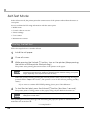
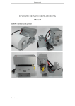
Technical Reference Guide
Product Overview
Describes features and general specifications for the product.
Setup
Describes setup and installation of the product and peripherals.
Application Development Information
Describes how to control the printer and necessary information
when you develop applications.
Handling
Describes how to handle the product.
Appendix
Describes interfaces, connectors, and character code tables.
M00053500
Rev. A
Cautions
• No part of this document may be reproduced, stored in a retrieval system, or transmitted in any form
or by any means, electronic, mechanical, photocopying, recording, or otherwise, without the prior
written permission of Seiko Epson Corporation.
• The contents of this document are subject to change without notice. Please contact us for the latest
information.
• While every precaution has been taken in the preparation of this document, Seiko Epson Corporation assumes no responsibility for errors or omissions.
• Neither is any liability assumed for damages resulting from the use of the information contained
herein.
• Neither Seiko Epson Corporation nor its affiliates shall be liable to the purchaser of this product or third
parties for damages, losses, costs, or expenses incurred by the purchaser or third parties as a result of:
accident, misuse, or abuse of this product or unauthorized modifications, repairs, or alterations to this
product, or (excluding the U.S.) failure to strictly comply with Seiko Epson Corporation’s operating
and maintenance instructions.
• Seiko Epson Corporation shall not be liable against any damages or problems arising from the use of
any options or any consumable products other than those designated as Original EPSON Products or
EPSON Approved Products by Seiko Epson Corporation.
Trademarks
EPSON is a registered trademark of Seiko Epson Corporation in Japan and other countries/regions.
Microsoft and Windows are registered trademarks of Microsoft Corporation.
2
For Safety
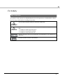
Key to Symbols
The symbols in this manual are identified by their level of importance, as defined below. Read
the following carefully before handling the product.
You must follow warnings carefully to avoid serious bodily injury.
WARNING
CAUTION
Provides information that must be observed to prevent damage to the equipment or loss of
data.
Possibility of sustaining physical injuries.
Possibility of causing physical damage.
Possibility of causing information loss.
Provides information that must be observed to avoid damage to your equipment or a
malfunction.
Provides important information and useful tips.
3
Warnings
WARNING
4
To avoid risk of electric shock, do not set up this product or handle cables during a
thunderstorm
Never insert or disconnect the power plug with wet hands.
Doing so may result in severe shock.
Handle the power cable with care.
Improper handling may lead to fire or electric shock.
Do not modify or attempt to repair the cable.
Do not place any heavy object on top of the cable.
Avoid excessive bending, twisting, and pulling.
Do not place the cable near heating equipment.
Check that the plug is clean before plugging it in.
Be sure to push the plug all the way in.
Be sure to use the specified power source.
Connection to an improper power source may cause fire or shock.
Do not place multiple loads on the power outlet.
Overloading the outlet may lead to fire.
Shut down your equipment immediately if it produces smoke, a strange odor, or
unusual noise.
Continued use may lead to fire. Immediately unplug the equipment and contact your
dealer or a Seiko Epson service center for advice.
Never attempt to repair this product yourself.
Improper repair work can be dangerous.
Never disassemble or modify this product.
Tampering with this product may result in injury or fire.
Do not allow foreign matter to fall into the equipment.
Penetration by foreign objects may lead to fire.
If water or other liquid spills into this equipment, do not continue to use it.
Continued use may lead to fire. Unplug the power cord immediately and contact your
dealer or a Seiko Epson service center for advice.
If you open the DIP switch cover, be sure to close the cover and tighten the screw
after adjusting the DIP switch.
Using this product with the cover open may cause fire or electric shock.
Do not use aerosol sprayers containing flammable gas inside or around this
product.
Doing so may cause fire.
Cautions
CAUTION
Do not connect cables in ways other than those mentioned in this manual.
Different connections may cause equipment damage or fire.
Be sure to set this equipment on a firm, stable, horizontal surface.
The product may break or cause injury if it falls.
Do not use this product in locations subject to high humidity or dust levels.
Excessive humidity and dust may cause equipment damage or fire.
Do not place heavy objects on top of this product. Never stand or lean on this
product.
Equipment may fall or collapse, causing breakage and possible injury.
Take care not to injure your fingers on the manual cutter:
When you remove printed paper.
When you perform other operations, such as loading/replacing roll paper.
Do not open the roll paper cover without taking the necessary precautions, as this
can result in injury from the autocutter fixed blade.
To ensure safety, unplug this product before leaving it unused for an extended
period.
Restriction of Use
When this product is used for applications requiring high reliability/safety, such as
transportation devices related to aviation, rail, marine, automotive, etc.; disaster prevention
devices; various safety devices; or functional/precision devices, you should use this product
only after giving consideration to including fail-safes and redundancies into your design to
maintain safety and total system reliability. Because this product was not intended for use in
applications requiring extremely high reliability/safety, such as aerospace equipment, main
communication equipment, nuclear power control equipment, or medical equipment related to
direct medical care, etc., please make your own judgement on this product's suitability after a
full evaluation.
Use of the TM-L500A RFID in other countries/areas than specified is strictly prohibited. For the
information on the countries/areas where you can use the TM-L500A RFID, see the information
sheet included with your model.
5
About this Manual
Aim of the Manual
This manual was created to provide information on development, design, and installation of
systems and development and design of printer applications for developers.
Manual Content
The manual is made up of the following sections:
Chapter 1
Product Overview
Chapter 2
Setup
Chapter 3
Application Development Information
Chapter 4
Handling
Appendix
Specifications of Interfaces and Connectors
Character Code Tables
6
Contents
■ For Safety...............................................................................................................................3
Key to Symbols ....................................................................................................................................... 3
Warnings ................................................................................................................................................. 4
Cautions.................................................................................................................................................. 5
■ Restriction of Use ..................................................................................................................5
■ About this Manual ................................................................................................................6
Aim of the Manual................................................................................................................................. 6
Manual Content .................................................................................................................................... 6
Product Overview ........................................................................11
■ Features ...............................................................................................................................11
■ Product Configurations ......................................................................................................12
Interfaces .............................................................................................................................................. 12
Colors .................................................................................................................................................... 12
Accessories........................................................................................................................................... 12
■ Part Names and Functions.................................................................................................13
Power Switch ........................................................................................................................................ 13
Control Panel ....................................................................................................................................... 13
Connectors........................................................................................................................................... 16
Offline .................................................................................................................................................... 16
■ Error Status ...........................................................................................................................17
Printer Errors .......................................................................................................................................... 17
Unrecoverable Errors ........................................................................................................................... 18
Data Receive Error (Only with the Serial Interface Models) ........................................................... 19
■ Power-Saving Mode ...........................................................................................................20
Sleep 1 & Sleep 2 ................................................................................................................................. 20
Sleep 3 .................................................................................................................................................. 21
■ NV Memory (Non-Volatile Memory) ................................................................................22
Memory Switches................................................................................................................................. 22
Maintenance Counter ........................................................................................................................ 22
■ Product Specifications .......................................................................................................23
Printing Specifications ......................................................................................................................... 24
Paper Specifications............................................................................................................................ 25
Specified Original Paper Types .......................................................................................................... 26
Printable Area ...................................................................................................................................... 27
Printing and Cutting Positions ............................................................................................................. 27
Electrical Characteristics .................................................................................................................... 28
Reliability............................................................................................................................................... 30
Environmental Conditions................................................................................................................... 31
External Dimensions and Mass ........................................................................................................... 32
7
Power Supply Unit (PS-180) ..................................................................................................................33
Setup .............................................................................................35
■ Flow of Setup....................................................................................................................... 35
■ Installing the Printer............................................................................................................ 35
Important Notes ...................................................................................................................................35
■ Setting the DIP Switches..................................................................................................... 36
Setting Procedure.................................................................................................................................36
For Serial Interface................................................................................................................................38
For USB Interface...................................................................................................................................39
For Ethernet Interface ..........................................................................................................................39
■ Connecting the Printer to the Host Computer ................................................................. 40
For Serial Interface................................................................................................................................40
For USB Interface...................................................................................................................................41
For Ethernet Interface ..........................................................................................................................42
■ Connecting the Power Supply Unit (PS-180) .................................................................... 43
Connecting the Power Supply Unit ....................................................................................................43
■ Setting the Memory Switches............................................................................................ 45
Functions ...............................................................................................................................................46
■ Setting Menu on the LCD ................................................................................................... 50
Application Development Information......................................51
■ How to Control the Printer.................................................................................................. 51
AEA Commands ...................................................................................................................................51
■ Software and Manuals ....................................................................................................... 51
■ Self-Test Mode .................................................................................................................... 52
Starting the Self-Test .............................................................................................................................52
Handling .......................................................................................53
■ Usage Precautions ............................................................................................................. 53
■ Installing and Replacing Paper ........................................................................................ 54
Installing Paper .....................................................................................................................................54
Replacing Paper ..................................................................................................................................55
■ Removing Jammed Paper ................................................................................................ 57
■ Cleaning the Printer ........................................................................................................... 59
8
Cleaning the Printer Case .................................................................................................................. 59
Cleaning the Thermal Head............................................................................................................... 59
■ Preparing for Transport .......................................................................................................61
Appendix......................................................................................63
■ Specifications of Interfaces and Connectors ..................................................................63
RS-232 Serial Interface ......................................................................................................................... 63
10BASE-T/100BASE-TX Ethernet Interface........................................................................................... 66
USB (Universal Serial Bus) Interface .................................................................................................... 68
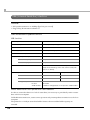
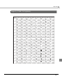
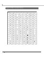
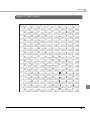
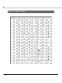
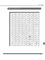
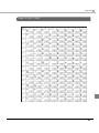
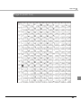
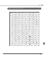
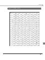
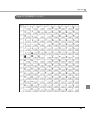
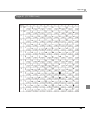
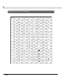
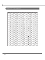
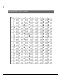
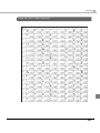
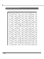
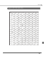
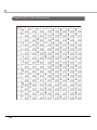
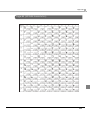
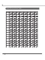
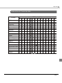
■ Character Code Tables......................................................................................................69
Common to All Pages ......................................................................................................................... 69
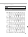
Page 0 [PC437: USA, Standard Europe] ............................................................................................ 70
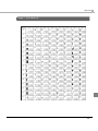
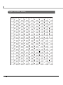
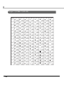
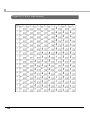
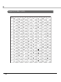
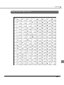
Page 1 (Katakana) .............................................................................................................................. 71
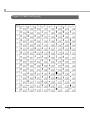
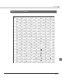
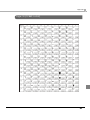
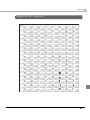
Page 2 (PC850: Multilingual) .............................................................................................................. 72
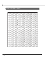
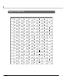
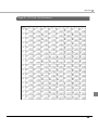
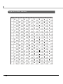
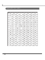
Page 3 (PC860: Portuguese)............................................................................................................... 73
Page 4 (PC863: Canadian-French) ................................................................................................... 74
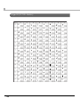
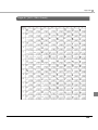
Page 5 (PC865: Nordic) ...................................................................................................................... 75
Page 11 (PC851: Greek) ..................................................................................................................... 76
Page 12 (PC853: Turkish) ..................................................................................................................... 77
Page 13 (PC857: Turkish) ..................................................................................................................... 78
Page 14 (PC737: Greek) ..................................................................................................................... 79
Page 15 (ISO8859-7: Greek) ............................................................................................................... 80
Page 16 (WPC1252)............................................................................................................................. 81
Page 17 (PC866: Cyrillic #2)................................................................................................................ 82
Page 18 (PC852: Latin2)...................................................................................................................... 83
Page 19 (PC858: Euro)......................................................................................................................... 84
Page 20 (KU42: Thai)............................................................................................................................ 85
Page 21 (TIS11: Thai) ............................................................................................................................ 86
Page 26 (TIS18: Thai) ............................................................................................................................ 87
Page 30 (TCVN-3: Vietnamese) ......................................................................................................... 88
Page 31 (TCVN-3: Vietnamese) ......................................................................................................... 89
Page 32 (PC720: Arabic) .................................................................................................................... 90
Page 33 (WPC775: Baltic Rim)............................................................................................................ 91
Page 34 (PC855: Cyrillic)..................................................................................................................... 92
Page 35 (PC861: Icelandic)................................................................................................................ 93
Page 36 (PC862: Hebrew) .................................................................................................................. 94
Page 37 (PC864: Arabic) .................................................................................................................... 95
Page 38 (PC869: Greek) ..................................................................................................................... 96
Page 39 (ISO8859-2: Latin2) ................................................................................................................ 97
Page 40 (ISO8859-15: Latin9) .............................................................................................................. 98
Page 41 (PC1098: Farsi)....................................................................................................................... 99
Page 42 (PC1118: Lithuanian) .......................................................................................................... 100
Page 43 (PC1119: Lithuanian) .......................................................................................................... 101
Page 44 (PC1125: Ukrainian) ............................................................................................................ 102
Page 45 (WPC1250: Latin 2) ............................................................................................................. 103
Page 46 (WPC1251: Cyrillic) ............................................................................................................. 104
Page 47 (WPC1253: Greek) .............................................................................................................. 105
9
Page 48 (WPC1254: Turkish) ..............................................................................................................106
Page 49 (WPC1255: Hebrew)............................................................................................................107
Page 50 (WPC1256: Arabic)..............................................................................................................108
Page 51 (WPC1257: Baltic Rim) ........................................................................................................109
Page 52 (WPC1258: Vietnamese) ....................................................................................................110
Page 53 (KZ1048: Kazakhstan) ..........................................................................................................111
Page 255 (User-Defined Page)..........................................................................................................112
International Character Sets.............................................................................................................113
10
Chapter 1 Product Overview
Product Overview
This chapter describes features and specifications of the product.
Features
The TM-L500A RFID is a high-speed compact printer suited for issuing RFID baggage tags.
The features are as follows:
RFID
1
UHF GEN2, Complies with IATA Resolution 1740C
Use of the TM-L500A RFID in other countries/areas than specified is strictly prohibited. For
the information on the countries/areas where you can use the TM-L500A RFID, see the
information sheet included with your model.
Printing
• High speed printing: Max. 200 mm/s {7.87"/s}
• Auto printing position adjustment
Handling
• Compact body for flexible installation locations
• High-speed autocutter
• An optional paper supply device
Software
• Command protocol based on the AEA2009
• Bar code and two-dimensional symbol printing is possible.
• Maintenance counter
Environment
ENERGY STAR qualified.
11
Product Configurations
Interfaces
• Serial (9 Pin D-Sub) UB + USB interface model
• Serial (25 Pin D-Sub) interface model
• Ethernet interface model
Colors
EDG (Epson Dark Gray)
Accessories
Included
• AC adapter (Model: PS-180)
• Cable hook
• User’s manual
Options
• Paper supply device (Model: SU-RPL500/RPL500B)
• USB/RS-232C D-sub9 interface board (Model: UB-U500)
• RS-232C D-sub25 interface board (Model: UB-S500)
• Ethernet interface board (Model: UB-E500)
These optional interface boards are only for the TM-L500A. Never use them with other
Epson printers. Also, never use other interface boards with the TM-L500A.
12
Chapter 1 Product Overview
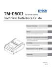
Part Names and Functions
Cover open lever
Control panel
1
Paper loading cover
Manual cutter
Power switch
Platen cover
Power Switch
Turns the printer on or off. The marks on the switch: (
: OFF/
: ON)
Before turning on the printer soon after turning it off, make sure the LEDs on the control
panel are off.
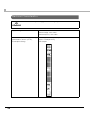
Control Panel
13
Power LED (Green)
• Lights when the power supply is on.
• Goes out when the power supply is turned off, or the printer is in the power-saving mode
(sleep 3).
On Line LED (Green)
• Lights when the printer is online.
• Goes out when the printer is offline (For details about offline, see "Offline" on page 16.) or in
the power-saving mode (sleep 3).
Error LED (Orange)
• Lights when the paper loading cover or the platen frame is open.
• Flashes when an error occurs. (For details about the flash codes, see "Error Status" on page 17.)
• Goes out during regular operation or the power-saving mode (sleep 3).
Paper LED (Orange)
• Lights when paper is out.
• Goes out when paper is loaded, or the printer is in the power-saving mode (sleep 3).
• Flashes in self-test printing standby state or autoloading standby state.
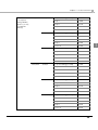
Unload () button
Holding down this button for 1 second or more feeds paper backward until the paper can be
removed from the back of the printer.
In the menu mode, this button switches the menu items and options.
Feed () button
If you use the label paper or paper with black marks,
• This button feeds paper to the print start position except during a printer error or the powersaving mode.
• This button ejects the paper when the status of the paper out sensor is paper not present and a
paper out error has not occurred.
If you use the continuous paper, this button feeds paper continuously except during a printer
error or the power-saving mode.
In the menu mode, this button switches the menu items and options.
On/Off Line (Back) button
This button switches between online and offline.
In the menu mode, this button returns to an upper menu item, or exits the menu mode.
14
Chapter 1 Product Overview
Menu (OK) button
This button enters the menu mode when the printer is offline.
In the menu mode, this button sets the displayed setting option.
For the setting items in the menu mode and setting procedures, see "Setting Menu on
the LCD" on page 50.
For information about the power-saving mode, see "Power-Saving Mode" on page 20.
Items displayed on the LCD
Printer status
Printer sub status
Normal condition
During printer error
Line 1 of LCD
Line 2 of LCD
Online
(Device mode)
(User ID): On Line
Offline
(Device mode)
(User ID): Off Line
Online
Prt Ready
(User ID): On Line
Online
(Device mode)
(User ID): On Line
Error
(Displays causes of printer
errors.)
During
unrecoverable error
Offline
Unrecoverable error
(Displays causes of
unrecoverable errors.)
In menu mode
First layer
[Setting menu]
(Menu name)
Second layer
[(Menu name)]
(Options)
1
During a printer error, the causes of the error are displayed in turn every other 2 seconds.
15
Connectors
All cables are connected to the connector panel on the lower rear of the printer.
Interface connectors
Ethernet
USB
Serial (9-Pin D-Sub)
Serial
(25-Pin D-Sub)
Power supply connector
• Interface connector:
Connects the printer with the host computer interface.
The interface type differs depending on the model. (See
"Interfaces" on page 12.)
• Power supply connector:
Connects the power supply unit.
For details on how to connect the interface connector and the power supply connector, see
"Connecting the Printer to the Host Computer" on page 40 and "Connecting the Power
Supply Unit (PS-180)" on page 43.
Offline
The printer automatically goes offline under the following conditions:
• Between the power is turned on (including the printer reset through the interface) and when
the printer is ready to receive data.
• During a self-test.
• During offline with the On/Off Line button.
• When in menu mode.
• When an unrecoverable error has occurred.
16
Chapter 1 Product Overview
Error Status
When an error occurs, the printer stops operating, the Error LED or Paper LED lights or flashes,
and the buzzer beeps (only when the buzzer function is enabled). If the error is a fatal one, the
printer goes offline.
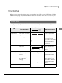
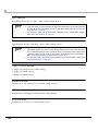
Printer Errors
Printing is no longer possible when printer errors occur. They can be recovered easily, as
described below.
LCD
indication
1
Error LED flash code
Error description
Approx.
320 ms
Recovery measure
High
temperature
The temperature of the
print head is extremely
high.
Recovers automatically
when the print head
cools.
Autocutter
Autocutting failed.
Open the platen frame,
remove the foreign
object, and then load the
appropriate paper. Or
send an error recovery
command.
Check paper
No black mark/hole
was found.
Check paper
Cover opened
Paper out sensor is in
the status of paper not
present.
Approx. 5120 ms
Approx. 3200 ms
The Error LED goes out.
The Paper LED lights.
Platen frame is open.
(including while
printing)
The Error LED lights.
Cover opened
Paper loading cover is
open.
Remove the paper in the
paper path, and then
load the appropriate
paper.
Remove the paper in the
paper path, and then
load the appropriate
paper.
Remove the paper in the
paper path, close the
platen frame, and then
load the appropriate
paper.
Close the paper loading
cover.
17
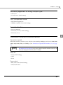
Error LED flash code
LCD
indication
Error description
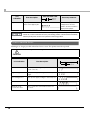
Paper JAM
Approx.
320 ms
Paper jam sensor has
detected a paper jam.
Recovery measure
Remove the paper
wrapped around the
platen, and then load the
appropriate paper.
When an Autocutter error occurs, do not turn the printer power off. If the printer power is
turned off, in case of autocutter error, the print starting position of the first sheet immediately
after the printer power is turned on is placed on the wrong position.
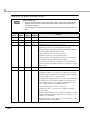
Unrecoverable Errors
Printing is no longer possible when fatal errors occur. The printer must be repaired.
Turn off the power immediately when a fatal error occurs.
CAUTION
Error LED flash code
LCD indication
Error description
Approx. 4800 ms
Approx.
320 ms
18
R/W error in memory
After R/W checking, the printer does not
work correctly.
High voltage error
The power supply voltage is extremely
high.
Low voltage error
The power supply voltage is extremely low.
CPU execution error
The CPU executes an incorrect address.
Internal circuit
connection error
The connection of internal circuit is not
correct.
Chapter 1 Product Overview
Data Receive Error (Only with the Serial Interface Models)
If any of the following errors occurs during serial interface communication, the printer prints “?”
or ignores the data.
• Parity error
• Framing error
• Overrun error
1
19
Power-Saving Mode
The TM-L500A RFID has the power-saving mode function to reduce the power consumption.
There are 3 statuses, sleeps 1, 2, and 3 in the power-saving mode.
For the power consumption during standby in each sleep mode, see "Electrical
Characteristics" on page 28.
Sleep 1 & Sleep 2
You can set the statuses, Sleeps 1 & 2 to any of the 3 patterns in the table below with the memory
switch.
• Sleep 1:
The printer enters this mode 10 seconds after entering standby status.
• Sleep 2:
The printer enters this mode 5 minutes after entering standby status.
In the default setting (Pattern 1), if the printer does not operate for 10 seconds, the LEDs and the
backlight of the LCD become dim, and for 5 minutes, the backlight of the LCD is turned off. They
come back on when the printer operates.
Patterns for
sleep 1 and sleep2
No power saving
Pattern 1 (initial setting)
Pattern 2
Pattern 3
Status
LEDs brightness
LCD backlight brightness
—
Bright
Bright (initial setting*1)
Normal
Bright
Bright (initial setting*1)
Sleep 1
Dim
Dim*2
Sleep 2
Dim
Off
Normal
Bright
Bright (initial setting*1)
Sleep 1
Dim
Dim*2
Normal
Bright
Bright (initial setting*1)
Sleep 1
Bright
Dim*2
Sleep 2
Bright
Dim*2
*1: Selectable from Bright, Dim, and Off with the control panel or the memory switch.
*2: If the LCD brightness during the normal status is set to Off, the LCD does not become dim.
Standby status is a status when no processing is being performed for printing or
communication, and the cover is closed.
When printing data is received, it is printed immediately.
For details on how to set the memory switch, see "Setting the Memory Switches" on
page 45.
20
Chapter 1 Product Overview
Sleep 3
When Sleep 3 is enabled with the memory switch, the printer enters this mode 4 hours after
entering standby status.
During Sleep 3, the LEDs and the backlight of the LCD are off, and no operation is available.
The printer recovers to the normal status when you perform any of the following;
• Push one of the panel buttons.
• Open the paper loading cover.
• Turn the printer power off, and turn it back on. (Turn the printer power on after 3 seconds or
more have passed.)
1
21
NV Memory (Non-Volatile Memory)
The printer's NV memory stores data even after the printer power is turned off. NV memory
contains the following memory areas for the user:
• Memory switches
• Maintenance counter
As a guide when you program applications, NV memory should be rewritten 10 or fewer
times a day.
Memory Switches
With the memory switches, which are software switches for the printer, you can configure
various settings of the printer.
For information about the memory switches see "Setting the Memory Switches" on page 45.
Maintenance Counter
With this function, printer information, such as the number of lines printed, the number of MICR
readings, the number of autocuts, and printer operation time after the printer starts working, is
automatically stored in NV memory. You can read or reset the information with the TM-L500A
Utility to use it for periodical checks or part replacement.
22
Chapter 1 Product Overview
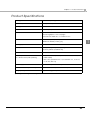
Product Specifications
Printing method
Thermal line printing
Dot density
203 dpi × 203 dpi
Printing direction
Unidirectional with friction feed
Paper width
54.0 mm {2.13"}
Number of characters
Alphanumeric characters: 95
Extended graphics: 128 × 30 pages
International characters: 16 character sets
Character structure
PECTAB: 5 cpi, 10 cpi, 17 cpi
1
TEMPLATE: Arbitrary width (cpi)
Cutting type
Full cut
Interfaces
Serial (RS-232), USB (2.0 Full-speed),
Ethernet (10BASE-T/100BASE-TX)
Receive buffer
4 KB
Bar code/
two-dimensional symbol printing
Two-dimensional symbols (PDF417, QR code, Aztec,
Data-matrix)
Bar codes (Interleaved 2 of 5, Industrial 2 of 5, Code 39,
Code 128, EAN 13)
Power supply
Epson PS-180 (Model: M159B)
Overall dimensions (H × W × D)
148 × 156 × 236 mm {5.83 × 6.14 × 9.29"}
Weight (mass)
Approx. 2.8 kg {6.17 lb}
dpi: dots per inch
cpi: characters per inch
23
Printing Specifications
Printing method
Thermal line printing
Dot density
203 dpi × 203 dpi
Printing direction
Unidirectional with friction feed
Paper width
54.0 mm {2.13"}
Printing width
50.8 mm (2.00"), 407 dots
Maximum printing speed
Text printing (Roll paper)
200 mm/s {7.87"/s}
Bar code/2-dimensional symbol printing
126 mm/s {4.96"/s}
Note: The printing speeds listed above are the values when the printer prints with the standard print density
level at 24V and 25°C {77°F}.
Printing speed can be changed with the memory switch. (See "Setting the Memory
Switches" on page 45.)
Printing speed may be slower, depending on such items as the data transmission speed.
24
Chapter 1 Product Overview
Paper Specifications
Paper must not be pasted to the roll paper spool.
If preprinted thermal paper is used, sticking (a problem of the thermal head sticking to
the surface of the thermal paper during printing) may occur, causing faulty printing and
other problems. Preprinting may also cause drop in the print density.
RFID Baggage tag
Complies with IATA RESOLUTION 1740C.
Type
Thermal paper
Form
Roll paper (The chromogenic side must face outside.)
Width
54.0 mm ± 0.5 mm {2.13" ± 0.02"}
Length
400 to 600 mm {15.75" to 23.62"}
Length detection
Optical-sensing (hole detection/backing paper (liner) detection)
RFID chip
Should be located 121± 4.5 mm {4.76 ± 0.18"} from the leading edge.
Thickness
220 µm or less (including backing paper)
Roll paper diameter
184.2 mm {7.25"} maximum
Roll paper inside core
76.2 mm {3.00"}
1
Take careful consideration in the print layout so that no printing is done on the backing
paper or outer edge.
Do not preprint (black marks or the equivalent print) in the joint between two backing
papers.
The transmission rate must be 57% or more for the backing paper, and 18% or less for
the backing paper + label paper.
The joint within a baggage tag must be 1 mm {0.039"} or less.
The hole size must be 1.6 to 6 mm {0.06 to 0.24"}.
The gap between labels must be 3.2 to 6 mm {0.13 to 0.24"}.
25
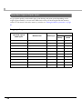
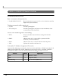
Specified Original Paper Types
For good print quality, set the media type, print density, and print speed, depending on the
original paper number, as shown in the tables below. They can be changed with the memory
switch. For information about the memory switches see "Setting the Memory Switches" on page
45.
Baggage tag
Recommended
Specified original
paper types
26
Manufacturer
Media type
Print
density
Print
speed
PolyTherm 300-3.0
Appleton
Type 3
02
High
PolyTherm 300-4.1
Appleton
Type 3
01
High
PolyTherm 500-4.1
Appleton
Type 2
02
High
Resiste 190-3.2
Appleton
Type 3
05
High
KPT 3370
Kanzaki Specialty Papers
Type 2
04
High
KPT 33100
Kanzaki Specialty Papers
Type 3
04
High
KLS46
Kanzan
Type 3
01
High
AL60KT-S
Jujo Thermal Oy
Type 1
06
High
140LES
RICOH
Type 2
05
High
150LCS-B
RICOH
Type 2
05
High
Chapter 1 Product Overview
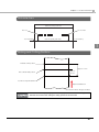
Printable Area
54.0 mm {2.13"} ± 0.5 mm
Dot no.409
Dot no.3
1.5 mm {0.059"}
50.8 mm {2.00"} (407 dots)
1.7 mm {0.067"}
1
Printing and Cutting Positions
Manual-cutter position
Approx. 31 mm
Autocutter blade position
Approx.
16 mm
Center of the print dotline
Paper feed direction
The numeric values are typical values.
The values above may vary slightly as a result of paper slack or variations in the paper.
Take this into account when setting the cutting position of the autocutter.
27
Electrical Characteristics
Be sure to use the power supply that came with your printer.
WARNING
Supply voltage
Epson PS-180
Rated voltage: 100 to 240V
Rated frequency: 50 to 60Hz
28
Power consumption during operating
Mean: Approx.34.4W (at 230V)
(USB interface, at 23C {73.4F},
normal print density)
Approx. 35.8W (at 115V)
Print sample
Chapter 1 Product Overview
Power
consumption
during standby
115V/60Hz
Serial I/F
(at 23C {73.4F},
normal print
density)
USB I/F
Ethernet I/F
230V/50Hz
Serial I/F
USB I/F
Ethernet I/F
No power-saving (normal)
1.26W
Sleep 1
1.00W
Sleep 2
0.61W
Sleep 3
0.33W
Power off
0.32W
No power-saving (normal)
1.21W
Sleep 1
0.94W
Sleep 2
0.56W
Sleep 3
0.34W
Power off
0.32W
No power-saving (normal)
3.20W
Sleep 1
2.94W
Sleep 2
2.59W
Sleep 3
0.35W
Power off
0.32W
No power-saving (normal)
1.38W
Sleep 1
1.12W
Sleep 2
0.73W
Sleep 3
0.44W
Power off
0.43W
No power-saving (normal)
1.33W
Sleep 1
1.06W
Sleep 2
0.67W
Sleep 3
0.45W
Power off
0.43W
No power-saving (normal)
3.36W
Sleep 1
3.09W
Sleep 2
2.73W
Sleep 3
0.46W
Power off
0.43W
1
29
If printing is continuously performed with a high ratio, the overcurrent protection may be
activated and result in uneven print density or a low voltage error. Therefore, the printing
length must not exceed the following values when printing with high print ratio.
Print width: Number of dots being energized per one dot line
Baggage tag
Total print width: 407 dots (50.8 mm {2.00"})
Print example
50.8 mm
Print length
20 mm {0.79"}
Reliability
Life
MTBF
30
Printer
Paper feeding of 100 km or 5 years, which comes first
Print head
100,000 baggage tags = 14 million lines
360,000 hours
Chapter 1 Product Overview
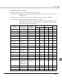
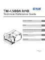
Environmental Conditions
Temperature/
Humidity
Operating
5 to 45°C {41 to 113°F}, 10 to 80% RH
Storage
-20 to 50°C {-4 to 122°F}, 10 to 90% RH (except for paper)
4GNCVKXG*WOKFKV[
[%RH]
90
34°C {93.2°F}, 80%
80
40°C {104°F}, 58%
60
1RGTCVKPIGPXKTQPOGPV
TCPIG
40
45°C {113°F}, 46%
1
20
10
0
Acoustic noise (operating)
0
10
20
30
40
50
#ODKGPVVGORGTCVWTG=͠?
Approximately 57 dB (bystander position) (including
autocutting operation)
Note:
The values above are measured in the Epson evaluation
condition.
Acoustic noise differs depending on the paper used, printing
contents, and the setting values, such as print speed or print
density.
31
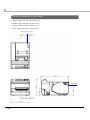
External Dimensions and Mass
• Height: Approximately 148 mm {5.83"}
• Width: Approximately 156 mm {6.14"}
• Depth: Approximately 236 mm {9.29"}
• Mass: Approximately 2.8 kg {6.17 lb}
Right edge of paper
Paper path
32
Chapter 1 Product Overview
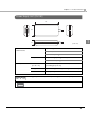
Power Supply Unit (PS-180)
136
68
1
33
[Unit: mm]
Electric
characteristics
Input conditions
Input voltage: AC100V to AC240V
Frequency: 50-60 Hz
Input current (rating): 1.3A
Output conditions
Output voltage (rating): DC24V ± 5%
Output current (rating): 2.1A
Case specifications
Dimensions
68 × 136 × 33 mm {2.68 × 5.35 × 1.30"}
(H × W × D)
(excluding projections)
Weight
Approx. 0.4 kg {14.11 oz} (excluding the AC cable)
Color
Black (matte)
For Energy Star printers, always use the power supply that came with your printer.
For detailed information about the PS-180, see the instruction manual for the PS-180.
33
34
Chapter 2 Setup
Setup
This chapter describes setup and installation of the product and peripherals.
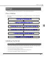
Flow of Setup
This chapter consists of the following sections, along with the setup flow of the product and
peripherals.
1. Installing the Printer (page 35)
2. Setting the DIP Switches (page 36)
2
3. Connecting the Printer to the Host Computer (page 40)
4. Connecting the Power Supply Unit (PS-180) (page 43)
5. Setting the Memory Switches (page 45)
6. Setting Menu on the LCD (page 50)
Installing the Printer
Important Notes
• Do not place other tags next to the printer, or the printer may write data on the tag outside.
• The printer must be installed horizontally on a flat surface (not tilted).
• Do not place the printer in dusty locations.
• Do not knock or strike the printer. This may cause printing errors.
• Do not place any liquids or drinks on the printer case.
35
Setting the DIP Switches
On this printer, you can make various settings with DIP switches.
Functions of the DIP switches differ depending on the interface.
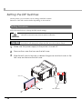
Setting Procedure
Follow the steps below to change the DIP switch settings.
Before you remove the DIP switch cover, turn the printer off.
Otherwise, a short-circuit may cause the printer to malfunction.
CAUTION
DIP switch settings are enabled only when the power is turned on or the printer is reset via
the interface. If the settings are changed after that, the functions will not change.
1
Make sure the power supply for the printer is turned off.
2
Remove the screw that secures the left case.
3
Slide the left case to the rear to release the groove and two hooks of the
left case, and remove the left case.
OFF
Groove
Hooks
36
DIP switches
ON
Chapter 2 Setup
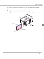
4
Set the DIP switches, using the tip of a tool, such as a small screwdriver.
5
Install the left case and secure it with the screw.
Align the groove on top of the left case with the rib of the upper case.
Align the two hooks of the left case with the two holes of the board plate and slide it to the
front.
Rib
Groove
2
Holes
Hooks
37
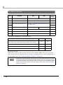
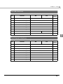
For Serial Interface
SW
Function
ON
Initial
setting
OFF
1
Reserved (Do not change)
Fixed to ON
ON
2
Reserved (Do not change)
Fixed to OFF
OFF
See the “ Transmission Speed (DIP Switches 3/
4)” table below.
ON
3
Transmission speed selections
4
Enabled
Disabled
ON
5
DSR (hardware) reset
OFF
6
Reserved (Do not change)
Fixed to OFF
OFF
7
Reserved (Do not change)
Fixed to OFF
OFF
8
Reserved (Do not change)
Fixed to OFF
OFF
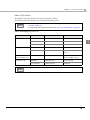
Transmission Speed (DIP Switches 3/4)
Transmission speed (bps)
SW 3
SW 4
Setting with the memory switch*:
2400, 4800, 9600, 19200 (initial setting), 38400, 57600, 115200
ON
ON
9600
OFF
ON
19200
ON
OFF
38400
OFF
OFF
bps: bits per second
* When DIP switches 3 and 4 are set to ON, the value (initially 19200) can be set to any of the
values listed in the lower portion of the row using a command, memory switch setting mode, or
the TM-L500A Utility. (See "Setting the Memory Switches" on page 45.)
Depending on print conditions, such as print duty, print head temperature, and data
transmission speed, print speed is automatically adjusted, which can cause white lines due
to intermittent print (the motor sometimes stops). To avoid this, set the transmission speed
higher or keep the print speed constant by setting it lower. (See "Setting the Memory
Switches" on page 45.)
38
Chapter 2 Setup
For USB Interface
SW
Function
ON
OFF
Initial
setting
1
Reserved (Do not change)
Fixed to ON
ON
2
Reserved (Do not change)
Fixed to OFF
OFF
3
Reserved (Do not change)
Fixed to ON
ON
4
Reserved (Do not change)
Fixed to ON
ON
5
Reserved (Do not change)
Fixed to OFF
OFF
6
Reserved (Do not change)
Fixed to OFF
OFF
7
USB interface class
8
Reserved (Do not change)
Printer class
Vendor class
Fixed to OFF
OFF
OFF
2
For Ethernet Interface
SW
Function
ON
OFF
Initial
setting
1
Reserved (Do not change)
Fixed to ON
ON
2
Reserved (Do not change)
Fixed to OFF
OFF
3
Reserved (Do not change)
Fixed to ON
ON
4
Reserved (Do not change)
Fixed to ON
ON
5
Reserved (Do not change)
Fixed to OFF
OFF
6
Reserved (Do not change)
Fixed to OFF
OFF
7
Reserved (Do not change)
Fixed to OFF
OFF
8
Reserved (Do not change)
Fixed to OFF
OFF
39
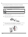
Connecting the Printer to the Host Computer
For Serial Interface
Connect the printer to a host computer by a serial interface (RS-232) cable.
Be sure to turn off the power supply for both the printer and host computer before
connecting the cables.
WARNING
Use a null modem serial cable to connect the printer.
1
2
3
4
40
Insert the interface cable connector firmly into the interface connector
on the connector panel.
When using connectors equipped with screws, tighten the screws to
secure the connectors firmly.
When using interface cables equipped with a grounding line, attach the
ground line to the screw hole marked “FG” on the printer.
Connect the other end of the interface cable to the host computer.
Chapter 2 Setup
For USB Interface
Connect the printer to a host computer by a USB interface cable.
1
Install the cable hook.
2
Put the USB cable through the cable hook.
Putting the USB cable through the cable hook prevents the cable from coming unplugged.
3
4
Connect the USB cable from the host computer to the USB upstream
connector.
Connect the other end of the interface cable to the host computer.
41
2
For Ethernet Interface
Connect the printer to a network by a LAN cable via a hub.
CAUTION
When LAN cables are installed outdoors, make sure devices without proper surge
protection are cushioned by being connected through devices that do have surge
protection.
Otherwise, the devices can be damaged by lightning.
Never attempt to connect the customer display cable, drawer kick-out cable, or a
standard telephone line cable to the 10/100BASE-T LAN connector.
For Ethernet interface communication settings, use TM-L500A Utility or EPSON TMNet
WinConfig utility. For detailed information about the setting methods, see the TM-L500A
Utility User’s Manual or EPSON TM Net WinConfig User’s Guide.
Connect a 10/100BASE-T cable to the 10/100BASE-T LAN connector by pressing firmly until the
connector clicks into place.
42
Chapter 2 Setup
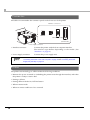
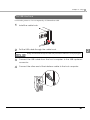
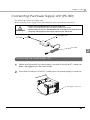
Connecting the Power Supply Unit (PS-180)
Use the PS-180 as the power supply unit.
Before using the power supply unit, read carefully the user’s manual enclosed with it.
WARNING
Always use the EPSON PS-180 as the power supply unit.
Using a nonstandard power supply can result in electric shock and fire.
Should a fault ever occur in the EPSON PS-180, immediately turn off the power to
the printer and unplug the power supply cable from the wall socket.
Power supply unit
DC cable
AC cable
2
Connecting the Power Supply Unit
1
2
Make sure the printer’s power supply is turned off and the AC cable has
been unplugged from the wall socket.
Insert the connector of the DC cable onto the power supply connector.
Power supply connector
43
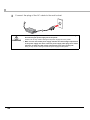
3
Connect the plug of the AC cable to the wall socket.
WARNING
44
Be sure to unplug the AC cable from the wall socket whenever connecting or
disconnecting the power supply unit to the printer.
Failure to do so may result in damage to the power supply unit or the printer.
Make sure the wall socket power supply satisfies the rated voltage requirements
of the power supply unit. Never insert the power supply cable plug into a socket
that does not meet the rated voltage requirements of the power supply unit.
Doing so may result in damage to both the power supply and the printer.
Chapter 2 Setup
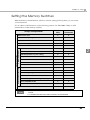
Setting the Memory Switches
With the memory switch function, which is software setting for this printer, you can set the
various functions.
For an outline of the functions, see the following section. Use TM-L500A Utility or AEA
commands to set the memory switches.
TM-L500A
Utility
AEA
Commands
Data receive error
✔
✔
Automatic line spacing
✔
✔
Paper jam detection
✔
✔
USB power saving
✔
✔
Serial DSR software reset
✔
✔
Default character code table
✔
✔
Default international character font
✔
✔
Transition pattern for power saving
✔
✔
Sleep 3
✔
✔
Adjustment of TOF-cut position
✔
✔
Customized Values
Model’s Unique Functions
Memory Switches
Settings\Setting Methods
✔
Print density
Print speed
✔
✔
User/Context mode
✔
✔
Buzzer volume
✔
✔
LCD backlight brightness
✔
✔
LCD contrast
✔
✔
AEA error judgement for wrong coupon type
✔
✔
Font compatible mode
✔
✔
Truncate function
✔
✔
✔
✔
Transmission conditions for serial interface
2
For detailed information about the TM-L500A Utility, see the TM-L500A Utility User’s
Manual.
For detailed information about AEA commands, see the AEA2009.
45
Functions
Data receive error
• Ignored
• Receive error (initial setting)
Automatic line spacing
• Always enabled
• Always disabled (initial setting)
Paper jam detection
• Disabled
• Enabled (initial setting)
Setting of paper jam detection is invalid for the model with corner R detection.
USB power saving
• Disabled
• Enabled (initial setting)
Serial DSR software reset
• Resets (initial setting)
• Does not reset
Default character code table
Selectable from 30 pages (initial setting: PC437 USA, Standard Europe)
Default international character font
Selectable from 16 types (initial setting: USA)
46
Chapter 2 Setup
Transition pattern for power saving
• No power saving
• Pattern 1 (initial setting)
• Pattern 2
• Pattern 3
Sleep 3
For good print quality, set the media type, depending on the original paper number. (See
"Paper Specifications" on page 25.)
• Enabled
• Disabled (initial setting)
2
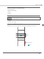
Adjustment of TOF-cut position
Selectable from -8 mm to 8 mm (The initial setting differs depending on the model.)
~ +8 mm
~ -8 mm
Paper feed direction
Hole
47
Print density
Selectable from levels 1 to 9 (70% 110%) (initial setting: level 7)
If the print density is set to a darker level, printing speed may be reduced.
If the print density is set to a darker level, paper dust accumulates on the print head and
print may be faint. For information on how to clean the thermal head, see "Cleaning the
Thermal Head" on page 59.
For good print quality, set the print density, depending on the original paper number.
(See "Paper Specifications" on page 25.)
Print speed
Selectable from levels 1 to 10 (Slow Fast) (initial setting: level 6)
Depending on print conditions, such as print duty, print head temperature, and data
transmission speed, print speed is automatically adjusted, which may cause white lines
due to intermittent print (the motor sometimes stops). To avoid this, keep the print speed
constant by setting it lower, or set the transmission speed higher for the serial interface.
(See "Transmission Speed (DIP Switches 3/4)" on page 38.)
For good print quality, set the print speed, depending on the original paper number. (See
"Paper Specifications" on page 25.)
User/Context mode
• Single user/Single context (initial setting)
• Single user/Multi context
• Multi user/Multi context
Buzzer volume
Selectable from Off and levels 1 to 5 (initial setting: level 5)
LCD backlight brightness
Selectable from Off, Bright and Dim (initial setting: Bright)
LCD contrast
Selectable from levels 1 to 3 (initial setting: level 3)
48
Chapter 2 Setup
AEA error judgement for wrong coupon type
• AEA error
• No AEA error (initial setting)
Font compatible mode
• PECTAB-compliant font
• IER506-compatible font (initial setting)
Truncate function
• Does not truncate
• Truncates (no error) (initial setting)
• Truncates (error)
2
Transmission conditions for serial interface
Transmission speed
When DIP switches 3 and 4 are set to ON, the value (initially 19200 bps) can be set to 2400, 4800,
9600, 19200, 38400, 57600, or 115200 bps. (See "Transmission Speed (DIP Switches 3/4)" on page
38.)
The transmission speed can be set with DIP switches 3 and 4 (See "Transmission Speed
(DIP Switches 3/4)" on page 38.) or the memory switch. When DIP switches 3 and 4 are set
to ON, the setting with the memory switch is enabled.
Parity bit
• None (initial setting)
• Odd
• Even
Flow control
• RTS/CTS control (initial setting)
• DTR/DSR control
49
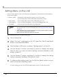
Setting Menu on the LCD
You can set the buzzer volume, LCD contrast, LCD brightness, and clock time with the buttons
on the control panel.
• Buzzer volume:
The buzzer sounds when the printer is in an error status.
You can adjust the volume of the buzzer from OFF to level 5.
• LCD contrast:
You can adjust the contrast of the LCD from level 1 to 3.
• LCD brightness:
You can select the brightness of the LCD from Bright/Dim/Off.
• Clock time:
You can set year, month, date, hour, and minute.
The buzzer volume, LCD contrast, LCD brightness, and clock time can be set also with
the customized value. To set the customized value, see "Setting the Memory Switches"
on page 45.
When resetting the RTC, moves automatically to the panel operation display for inputting
year, month, day, and time after starting up.
When the RTC has been reset, RFID cannot be used.
Follow the steps below to set menu on the LCD.
1
2
3
4
5
6
Turn on the printer.
When “On Line” is displayed on the LCD, press the ON/Off Line (Back)
button to put the printer offline.
Press the Menu (OK) button to display “[Setting menu]” on the LCD.
Use the Unload () button and Feed () button to display the setting
item for which you want to make a setting, and press the Menu (OK)
button to select it.
Use the Unload () button and Feed () button to display the setting
options, and press the Menu (OK) button to set it.
To make another setting, press the On/Off Line (Back) button once to
return to the menu selecting screen.
To finish setting, press the On/Off Line (Back) button twice to exit the menu mode.
50
Chapter 3 Application Development Information
Application Development Information
This chapter describes how to control the printer and gives information useful for printer
application development.
How to Control the Printer
Use AEA commands to control the printer.
AEA Commands
AEA specifications for Automated Ticket and Boarding Pass equipment (ATB), Parametric
Tables (PECTAB), Self Service and Baggage Tag Printers (BTP) related firmware are an industry
standard.
See the AEA2009 for more details.
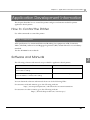
Software and Manuals
3
The following software and manuals are provided for application development.
Software
Manual
TM-L500A Utility User’s Manual
TM-L500A Utility:
Use for various settings.
EPSON TM Net WinConfig:
EPSON TM Net WinConfig User’s Guide
Use for IP address or wireless LAN setting.
You can obtain the software and manuals from one of the following URLs.
For customers in North America, go to the following web site:
http://www.epsonexpert.com/ and follow the on-screen instructions.
For customers in other countries, go to the following web site:
https://download.epson-biz.com/?service=pos/
51
Self-Test Mode
In the self-test mode, the printer prints the current status of the printer and resident characters as
a test print.
You can confirm the following information with the status print.
• Model name
• Control software version
• Printer settings
• User counter
• Maintenance counter
Starting the Self-Test
Follow the steps below to start the self-test.
1
Install the roll paper.
2
Close all covers.
3
While pressing the Unload () button, turn on the printer. (Keep pressing
the button until the printer starts printing.)
The printer starts printing the current status of the printer on the paper.
With the Ethernet interface, before printing starts, it takes 15 seconds if the IP address is
fixed and 20 seconds if the IP address is obtained with the automatic setting. (It may take
longer, depending on the response time from the host.)
When the printer finishes printing the current printer status, the following message is
printed and the Paper LED flashes. (The printer is now in the self-test printing standby
status.):
“If you want to continue SELF-TEST printing, please press Unload button.”
4
To start the test print, press the Unload () button (less than 1 second).
The printer prints a rolling pattern on the paper, using only the built-in character set.
If you press the Unload () button for more than 1 second, the printer prints the other
settings and counter value.
After printing the following message and autocutting the paper, the printer is initialized and
returned to the normal mode.
“*** completed***”
52
Chapter 4 Handling
Handling
This chapter describes basic handling of the printer.
Usage Precautions
• This printer is dedicated for RFID tag printing. The paper guide is fixed to the RF tag width,
and the paper width is unchangeable.
• Do not place other tags next to the printer, or the printer may write data on the tag outside.
• Install the printer horizontally.
• When installing, leave enough space around the printer for loading paper, turning on/off the
power switch, removing jammed paper, and so on.
• Make sure cords and foreign objects are not caught in the printer.
• Do not open the covers during printing or autocutting.
• Make sure that the printer is not subjected to any impact or vibration.
• Do not put any food or drink on the printer case.
• Do not move the printer with the paper loading cover open. The cover may close
unexpectedly.
• To prevent a paper jam, do not prevent paper from being ejected from the paper exit and do
not pull the paper being ejected.
4
53
Installing and Replacing Paper
WARNING
Do not open the covers during printing/autocutting.
The printer may be damaged.
Do not touch the manual cutter with your hands.
Otherwise, you may be injured because the manual cutter blade is sharp.
Use paper that meets the printer specifications. For details about paper specifications,
see "Paper Specifications" on page 25.
When changing the paper width, you need to remove or move the paper guide and to
change the setting for the paper width with the customized value. To change the paper
width, see "Setting the DIP Switches" on page 36.
To adjust the cutting position, define a character string in the CUTPOS field in the printer
environment data for baggage tags. (The adjustable range: -30 to 30)
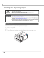
Installing Paper
When the Paper LED is on, follow the steps below to load paper.
54
1
Turn on the printer.
2
Open the paper loading cover by pulling up the cover open lever.
Chapter 4 Handling
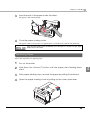
3
Insert the end of the paper under the rollers.
4
Close the paper loading cover.
The paper is fed automatically.
The paper is fed to the position of a punch hole or a black mark, and cut automatically.
Close the paper loading cover immediately. If it is left open for 1 minute or longer, paper
feeding may not be correct.
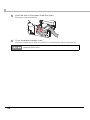
Replacing Paper
Follow the steps below to replace paper.
1
2
Turn on the printer.
Hold down the Unload () button until the paper starts feeding backward.
3
After paper feeding stops, remove the paper by pulling it backward.
4
Open the paper loading cover by pulling up the cover open lever.
55
4
5
Insert the end of the paper under the rollers.
6
Close the paper loading cover.
The paper is fed automatically.
The paper is fed to the position of a punch hole or a black mark, and cut automatically.
Close the paper loading cover immediately. If it is left open for 1 minute or longer, paper
feeding may not be correct.
56
Chapter 4 Handling
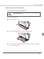
Removing Jammed Paper
When a paper jam occurs, never pull out the paper forcibly.
Follow the steps below to remove the jammed paper.
Do not touch the thermal head (See"Cleaning the Printer" on page 59.) because it can
be very hot after printing.
CAUTION
1
Turn off the printer.
2
Open the platen cover.
3
Push down the platen lever to open the platen frame.
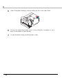
4
4
Pull out the jammed paper forward, and cut any distorted, crumpled, or
torn parts of the paper.
57
5
6
7
58
Open the paper loading cover by pulling up the cover open lever.
Pull out the paper backward, and cut any distorted, crumpled, or torn
parts of the paper if there are any.
Close the platen frame and the platen cover.
Chapter 4 Handling
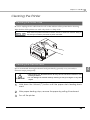
Cleaning the Printer
Cleaning the Printer Case
Be sure to unplug the AC cable from the wall socket and turn off the printer before cleaning.
Wipe the dirt off the printer case with a dry cloth or a damp cloth.
Never clean the product with alcohol, benzine, thinner, or other such solvents. Doing so
may damage or break the parts made of plastic and rubber.
Cleaning the Thermal Head
4
Epson recommends cleaning the thermal head periodically (generally every 3 months) to
maintain receipt print quality.
CAUTION
1
After printing, the thermal head can be very hot. Do not touch it and let it cool
before you clean it.
Do not damage the thermal head by touching it with your fingers or any hard
object.
Hold down the Unload () button until the paper starts feeding backward.
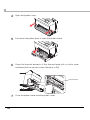
2
After paper feeding stops, remove the paper by pulling it backward.
3
Turn off the printer.
59
4
Open the platen cover.
5
Push down the platen lever to open the platen frame.
6
Clean the thermal elements of the thermal head with a cotton swab
moistened with an alcohol solvent (ethanol or IPA).
Thermal head
7
60
Close the platen frame and the platen cover.
Chapter 4 Handling
Preparing for Transport
Follow the steps below to transport the printer.
1
Turn off the printer.
2
Remove the power supply connector.
3
Remove the roll paper.
4
Pack the printer upright.
4
61
62
Appendix
Appendix
Specifications of Interfaces and Connectors
RS-232 Serial Interface
Interface board specifications (RS-232-compliant)
Item
Specifications
Data transfer method
Serial
Synchronization
Asynchronous
Handshake
Select one of the following with a memory switch:
DTR/DSR
RTS/CTS
Signal level
MARK
-3V to -15V logic “1”/OFF
SPACE
+3V to +15V logic “0”/ON
Transmission speed
Select one of the following with DIP switches 3 and 4:
[bps: bits per second]
9600/19200/38400 bps
Select one of the following with a memory switch:
2400/4800/9600/19200/38400/57600/115200 bps
Bit lengths
8 bits
Parity selection
Select one of the following with a memory switch:
None
Even
Odd
Stop bit
1 or more bits
However, the stop bit for data transfer from the printer is fixed to
1 bit.
Connector
Printer side
DSUB 9-pin (male) connector, DSUB 25-pin (female) connector
63
Functions of each connector pin
Receive buffer full:
When the remaining space in the receive buffer drops to 128 bytes, the printer status
becomes "buffer full" and it remains "buffer full" until the space in the receive buffer
increases to 256 bytes.
The printer ignores the data received when the remaining space in the receive buffer is 0
byte.
DSUB9
Pin no.
DSUB25
Pin no.
Signal
name
Signal
direction
1
—
NC
—
Not connected
2
3
RXD
Input
Receive data
3
2
TXD
Output
Transmit data
4
20
DTR
Output
<When RTS/CTS flow control is selected>
Function
Indicates whether or not the printer power is ON.
SPACE indicates that the printer power is ON, and MARK
indicates that the printer power is OFF.
<When DTR/DSR flow control is selected>
Indicates whether or not the printer is BUSY.
SPACE indicates that the printer is ready to receive data,
and MARK indicates that the printer is BUSY.
The printer goes BUSY when the printer is made offline by
pressing down the On/Off Line button or when the receive
buffer is full.
5
7
GND
—
Signal ground
6
6
DSR
Input
<When RTS/CTS flow control is selected>
Indicates whether or not the host computer power is ON.
SPACE indicates that the host computer is ON, and MARK
indicates that the host computer is OFF.
Changing the setting of DIP switch or memory switch allows
this signal to be used as a reset signal for the printer. This
reset signal is used for detecting the MARK status of the
host computer and for resetting the printer.
<When DTR/DSR flow control is selected>
Indicates whether or not the host computer is ready to
receive data.
SPACE indicates that the host computer is ready to receive
data, and MARK indicates that the host computer is not to
ready to receive data.
When DTR/DSR control is selected, check the status of this
signal before transmitting data.
64
Appendix
DSUB9
Pin no.
DSUB25
Pin no.
Signal
name
Signal
direction
7
4
RTS
Output
Function
<When RTS/CTS flow control is selected>
Indicates whether or not the printer is BUSY.
SPACE indicates that the printer is ready to receive data,
and MARK indicates that the printer is BUSY.
The printer goes BUSY when the printer is made offline by
pressing down the On/Off Line button or when the receive
buffer is full.
<When DTR/DSR flow control is selected>
Indicates whether or not the printer power is ON.
SPACE indicates that the printer power is ON, and MARK
indicates that the printer power is OFF.
8
5
CTS
Input
<When RTS/CTS flow control is selected>
Indicates whether or not the host computer is ready to
receive data.
SPACE indicates that the host computer is ready to receive
data, and MARK indicates that the host computer is not
ready to receive data.
When RTS/CTS control is selected, check the status of this
signal before transmitting data.
<When DTR/DSR flow control is selected>
This signal is not used.
9
—
SG
—
Signal ground
65
10BASE-T/100BASE-TX Ethernet Interface
Software specifications
Basic communication protocols
• IP, ARP, ICMP, UDP, TCP:
Basic communications protocols for various functions (used by
higher-level protocols below)
Printing communications protocols
• LP, LPR:
Transfers printing data.
• TCP socket port:
Transfers printing data and printer status with direct socket
communications (bi-directional).
Protocol for obtaining status and setting
• HTTP:
Displays module status and makes setting with the Web
browser.
• SNMP:
Obtains status and/or sets module or printer with the
dedicated/commercial MIB tool.
• ENPC:
Obtains status and/or sets the interface unit and printer.
• TFTP:
Updates the interface unit firmware.
Automatic IP Address Assignment Protocols
Automatic IP addressing is executed in order shown in the table below. If DHCP is disabled or IP
addressing for DHCP fails, then IP addressing for the next protocols is executed. If APIPA is
disabled or IP address cannot be obtained, the internal setting parameters are used.
Protocol
66
Order
Application
DHCP
1
Obtains IP address.
APIPA
2
Assigns IP address.
Manual setting
3
Uses the internal parameters.
Appendix
Internal parameter settings
Internal parameter settings can be changed with the following:
• ENPC protocol: Epson provides a dedicated utility that makes miscellaneous setting with the
ENPC protocol.
• HTTP browser: An HTTP browser can make setting when connected to the module.
• arp commands and ping commands (Only IP address is settable.):
This function is available only when it has been enabled. The setting can be
made only from a host PC that supports both arp and ping commands and is
in the same segment as the module.
Default
values
View
Setting
View
Setting
Status
sheet
print
IP address
192.168.192.168
Yes
Yes
Yes
Yes
Yes
Subnet mask
255.255.255.0
Yes
Yes
Yes
Yes
Yes
Gateway address
0.0.0.0
Yes
Yes
Yes
Yes
Yes
Article
Parameters
Utility
Browser
DHCP
Enable/Disable
Disable
Yes
Yes
Yes
Yes
Yes
APIPA
Enable/Disable
Disable
Yes
Yes
Yes
Yes
Yes
Arp/ping IP setting
Enable/Disable
Enable
Yes
Yes
Yes
Yes
No
Community name 1
(read-only)
Max. 16
characters
“public”
Yes
No
Yes
No
Yes
Community name 2
(read-write)
Max. 16
characters
None
Yes
Yes
Yes
Yes
Yes
IP Trap 1 Enable
Enable/Disable
Disable
Yes
Yes
Yes
Yes
No
IP Trap 2 Enable
Enable/Disable
Disable
Yes
Yes
Yes
Yes
No
Community name
(IP Trap #1)
Max. 16
characters
None
Yes
Yes
Yes
Yes
No
Community name
(IP Trap #2)
Max. 16
characters
None
Yes
Yes
Yes
Yes
No
IP trap #1 address
None
Yes
Yes
Yes
Yes
No
IP trap #2 address
None
Yes
Yes
Yes
Yes
No
Password
None
No
Yes
No
Yes
No
Physical layer
setting
Auto negotiation
/10Base-T Half
/10Base-T Full
/100Base-TX Half
/100Base-TX Full
Auto
negotiation
Yes
Yes
Yes
Yes
Yes
Hardware version
—
—
Yes
No
Yes
No
Yes
Firmware version
—
—
Yes
No
Yes
No
Yes
MAC address
—
—
Yes
No
Yes
No
Yes
67
USB (Universal Serial Bus) Interface
Outline
• Full-speed transmission at 12 Mbps [bps: bits per second]
• Plug & Play, Hot Insertion & Removal
USB transmission specifications
USB function
Overall specifications
USB 2.0
Transmission speed
USB Full-Speed (12 Mbps)
Transmission method
USB bulk transmission method
Power supply specifications
USB self power supply function
Current consumed by USB bus
0 mA
USB packet size (with full-speed connection)
USB bulk OUT (TM)
64 bytes
USB bulk IN (TM)
64 bytes
USB device class
Both vendor-defined class and USB printer class are
supported. Switching of the class can be set by DIP
switch on startup.
USB descriptor
USB vendor-defined class
USB printer class
Vendor ID
04b8h
04b8h
Product ID
0202h
0E08h
String Descriptor
Manufacturer
EPSON
Product
TM-L500A
Serial number
Character string based on the product serial number
Status transmission from printer with USB interface
In order to ensure that there is no lack of status data, it is necessary to periodically retrieve status
data at the host computer.
Unlike RS-232 transmission, status cannot spontaneously interrupt data transmission to the host
computer.
The printer has a 128-byte status data buffer. Statuses that exceed the buffer capacity are
canceled.
68
Appendix
Character Code Tables
The character code tables show only character configurations. They do not show the
actual print pattern.
“SP” in the table shows a space.
Common to All Pages
When the international character set (See "International Character Sets" on page 113.) is USA:
69
Page 0 [PC437: USA, Standard Europe]
70
Appendix
Page 1 (Katakana)
71
Page 2 (PC850: Multilingual)
72
Appendix
Page 3 (PC860: Portuguese)
73
Page 4 (PC863: Canadian-French)
74
Appendix
Page 5 (PC865: Nordic)
75
Page 11 (PC851: Greek)
76
Appendix
Page 12 (PC853: Turkish)
77
Page 13 (PC857: Turkish)
78
Appendix
Page 14 (PC737: Greek)
79
Page 15 (ISO8859-7: Greek)
80
Appendix
Page 16 (WPC1252)
81
Page 17 (PC866: Cyrillic #2)
82
Appendix
Page 18 (PC852: Latin2)
83
Page 19 (PC858: Euro)
84
Appendix
Page 20 (KU42: Thai)
85
Page 21 (TIS11: Thai)
86
Appendix
Page 26 (TIS18: Thai)
87
Page 30 (TCVN-3: Vietnamese)
88
Appendix
Page 31 (TCVN-3: Vietnamese)
89
Page 32 (PC720: Arabic)
90
Appendix
Page 33 (WPC775: Baltic Rim)
91
Page 34 (PC855: Cyrillic)
92
Appendix
Page 35 (PC861: Icelandic)
93
Page 36 (PC862: Hebrew)
94
Appendix
Page 37 (PC864: Arabic)
95
Page 38 (PC869: Greek)
96
Appendix
Page 39 (ISO8859-2: Latin2)
97
Page 40 (ISO8859-15: Latin9)
98
Appendix
Page 41 (PC1098: Farsi)
99
Page 42 (PC1118: Lithuanian)
100
Appendix
Page 43 (PC1119: Lithuanian)
101
Page 44 (PC1125: Ukrainian)
102
Appendix
Page 45 (WPC1250: Latin 2)
103
Page 46 (WPC1251: Cyrillic)
104
Appendix
Page 47 (WPC1253: Greek)
105
Page 48 (WPC1254: Turkish)
106
Appendix
Page 49 (WPC1255: Hebrew)
107
Page 50 (WPC1256: Arabic)
108
Appendix
Page 51 (WPC1257: Baltic Rim)
109
Page 52 (WPC1258: Vietnamese)
110
Appendix
Page 53 (KZ1048: Kazakhstan)
111
Page 255 (User-Defined Page)
HEX
0
8
9
Ç
É
128
1
ü
Æ
130
3
â
ô
ä
ö
5
à
å
7
ù
ê
9
153
ï
154
C
î
D
156
Ø
141
E
Ä
F
Å
112
¢
·
·
174
175
205
╬
190
·
¤
159
189
SP
SP
SP
253
SP
238
SP
223
252
237
222
SP
207
251
236
SP
SP
·
191
SP
SP
221
206
250
235
220
SP
249
SP
SP
SP
═
SP
234
219
204
248
233
SP
SP
╠
SP
SP
218
203
188
173
158
ş
143
╝
¡
Ş
╦
187
172
157
142
╗
202
247
232
217
SP
246
SP
SP
SP
╩
186
171
·
£
ì
║
SP
231
216
201
245
230
SP
SP
╔
SP
SP
215
200
185
170
155
140
╣
·
ø
139
╚
184
169
·
Ü
138
B
·
Ö
è
168
199
244
229
214
·
Ä
183
İ
¿
152
137
A
167
SP
SP
·
243
228
213
198
242
SP
SP
SP
â
182
À
ğ
ÿ
ë
166
151
136
Â
Ğ
SP
227
212
197
241
226
SP
SP
·
181
SP
SP
211
196
240
225
210
SP
·
Á
SP
SP
195
180
165
150
135
8
Ñ
û
ç
164
149
134
179
SP
224
209
194
·
·
ñ
ò
133
6
163
148
·
178
·
ú
208
193
F
SP
I
·
·
E
H
192
177
162
147
132
·
ó
D
·
176
161
146
131
4
160
145
C
·
í
æ
é
B
á
144
129
2
A
254
SP
239
255
Appendix
International Character Sets
Country
ASCII code (Hex)
23
24
25
2A
40
5B
5C
5D
5E
60
7B
7C
7D
7E
USA
France
#
$
%
*
@
[
\
]
^
`
{
|
}
~
#
$
%
*
à
°
ç
§
^
`
é
ù
è
¨
Germany
#
$
%
*
§
Ä
Ö
Ü
^
`
ä
ö
ü
β
U.K.
£
$
%
*
@
[
\
]
^
`
{
|
}
~
Denmark I
#
$
%
*
@
Æ
Ø
Å
^
`
æ
ø
å
~
Sweden
#
¤
%
*
É
Ä
Ö
Å
Ü
é
ä
ö
å
ü
Italy
#
$
%
*
@
°
\
é
^
ù
à
ò
è
ì
Spain I
Pt
$
%
*
@
¡
Ñ
¿
^
`
¨
ñ
}
~
Japan
#
$
%
*
@
[
¥
]
^
`
{
|
}
~
Norway
#
¤
%
*
É
Æ
Ø
Å
Ü
é
æ
ø
å
ü
Denmark II
#
$
%
*
É
Æ
Ø
Å
Ü
é
æ
ø
å
ü
Spain II
#
$
%
*
á
¡
Ñ
¿
é
`
í
ñ
ó
ú
Latin America
Korea
#
$
%
*
á
¡
Ñ
¿
é
ü
í
ñ
ó
ú
#
$
%
*
@
[
W
]
^
`
{
|
}
~
Slovenia/Croatia
#
$
%
*
Ž
Š
Đ
Ć
Č
ž
š
đ
ć
č
China
Vietnum
#
Ұ
%
*
@
[
\
]
^
`
{
|
}
~
₫
$
%
*
@
[
\
]
^
`
{
|
}
~
Arabia
#
$
%
*
@
[
\
]
^
`
{
|
}
~
113
114