1
TM-P60
Technical Reference
guide
EPSON
English
Rev. D
405018203
TM-P60 Technical Reference Guide
CAUTIONS
❏
This document shall apply only to the product(s) identified herein.
❏
No part of this document may be reproduced, stored in a retrieval system, or transmitted in any form or by any
means, electronic, mechanical, photocopying, recording, or otherwise, without the prior written permission of
Seiko Epson Corporation.
❏
The contents of this document are subject to change without notice. Please contact us for the latest information.
❏
While every precaution has been taken in the preparation of this document, Seiko Epson Corporation assumes no
responsibility for errors or omissions.
❏
Neither is any liability assumed for damages resulting from the use of the information contained herein.
❏
Neither Seiko Epson Corporation nor its affiliates shall be liable to the purchaser of this product or third parties
for damages, losses, costs, or expenses incurred by the purchaser or third parties as a result of: accident, misuse, or
abuse of this product or unauthorized modifications, repairs, or alterations to this product, or (excluding the U.S.)
failure to strictly comply with Seiko Epson Corporation's operating and maintenance instructions.
❏
Seiko Epson Corporation shall not be liable against any damages or problems arising from the use of any options
or any consumable products other than those designated as Original EPSON Products or EPSON Approved
Products by Seiko Epson Corporation.
TRADEMARKS
EPSON®
and
Microsoft®
ESC/POS®
Windows®
are registered trademarks of Seiko Epson Corporation.
and Windows NT® are registered trademarks of Microsoft Corporation.
General Notice: Other product and company names used herein are for identification purposes only and may be
trademarks of their respective companies.
ESC/POS® Proprietary Command System
EPSON took the initiative by introducing ESC/POS, a proprietary POS printer command system including patented
commands and enabling versatile POS system construction with high scalability. Compatible with all types of EPSON
POS printers and displays, this proprietary control system also offers the flexibility to easily make future upgrades. Its
popularity is worldwide.
Rev. D
i
The influence on the environment of radio wave radiation
❏ The Radio Frequency module that can be installed in this product radiates the same high
frequency energy as some other high frequency devices but the level of the energy radiated
from it is suppressed so that it is much lower than the electromagnetic energy radiated from
radio equipment like cell phones.
❏ Under some situations and in certain environments, the use of this equipment is sometimes
limited by the owner of the building or a representative with responsibility for the group.
For example, it may be restricted in the following case:
•
Use in an environment where it may cause interference with other devices and services.
❏ If you do not understand the radio device usage policy in a specific group or environment,
such as an airport, ask permission before turning on the power of this product.
Note about interference
❏ The Radio Frequency module that can be installed in this product generates, uses, and can
radiate radio frequency energy and, if not installed and used in accordance with the
instruction manual, may cause harmful interference to radio communications.
❏ If this equipment does cause harmful interference to radio or television reception, which can
be determined by turning the equipment off and on, the user is encouraged to try to correct
the interference by one or more of the following measures:
•
Reorient or relocate the receiving antenna.
•
Increase the separation between the equipment and receiver.
•
Connect the equipment into an outlet on a circuit different from that to which the
receiver is connected.
•
Consult your dealer or an experienced radio/TV technician for help.
❏ Never disassemble or modify this product or the installed Radio Frequency module.
❏ Seiko Epson Corporation shall not be liable for interference to radio/TV resulting from
changes or modifications to this product or the installed Radio Frequency module not
expressly approved by Seiko Epson Corporation.
❏ Other radio equipment sometimes uses the same frequency band that this unit uses. To
prevent radio wave interference with other radio equipment, pay attention to the following
matters when you use this product:
•
ii
The Radio Frequency module that can be installed in this product uses the Industrial
Scientific and Medical band (2.4 GHz), DS-SS modulation, and the interference distance
is 40 m.
Rev. D
TM-P60 Technical Reference Guide
•
Other equipment that uses the same frequency band used by the Radio Frequency
module that can be installed in this product includes equipment for industry, science
and medical treatment, microwave ovens, HomeRF, and radio and other broadcasting
equipment (both ones that require a license and ones that do not require a license).
•
Confirm that radio and other broadcasting equipment are not used nearby before using
this product.
•
When trouble occurs, for example, if the Radio Frequency module causes problems such
as radio wave interference, consult your dealer.
Note about security
This section describes security concerns when using a wireless LAN by using the Radio
Frequency module that can be installed in this product. Please also see “Wireless LAN Security”
in Appendix F.
Security is important for the protection of the user’s privacy
A wireless LAN has the advantage that information can be exchanged by using radio waves
instead of a cable. However, radio waves are not confined to a cable and can be received in a
fairly wide area and through obstacles such as walls, so if security is not used, the following
problems may occur.
❏ Communication data can be received by stealth.
A third person can receive private communication data by intercepting the radio waves
intentionally. Such a person could receive items such as the following:
•
Personal information, such a an ID and password or credit card number
•
The contents of e-mail.
•
Data which is communicated between the PC and printer.
❏ Illegal access
A third person can access the network and cause damage such as the following:
•
Personal information and secret information can be removed.
•
Invalid information can be sent as if it were from a legitimate user of the network.
•
Intercepted communication contents can be re-written and sent.
•
Data and the system can be destroyed by an electronic virus.
This product, the wireless LAN card, and the access point have security mechanisms to counter
these problems. If you use the security settings for this product, you can nearly eliminate these
problems.
In some cases, the wireless LAN equipment is not set up before it is sold to the user. Therefore,
to attempt to prevent security problems, always use all the security settings for the wireless
LAN equipment according to the manual.
Rev. D
iii
The security functions, however, cannot guarantee 100% security. Please understand this when
you use this product.
When you cannot set the security by yourself, please ask your dealer.
Seiko Epson Corporation suggests that the security setting is set by the judgment and the
responsibility of user after understanding the possible problems resulting from using this
product without the security settings.
For details, see “Wireless LAN Security” in Appendix F.
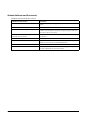
Revision Information
Revision
Page
Altered Items and Contents
Rev. A
All pages
Newly authorized
pp. vii-viii
EMC and Safety Standards Applied for Europe added.
RF Module Standards for Europe added.
p. 1-2
Standard parts included with the printer: AC adapter (included
only with some models) added.
p. 1-3
Description of the OT-ST60 (shoulder strap) added.
p. 2-6
Installing/replacing roll paper vertically added.
p. 4-2
The web address of “epson.pos.com” added.
D-5
WEB addresses added.
Appendix F
Wireless LAN Network Composition added.
All pages
Type of RF module changed.
pp. vii,ix-x
EMC and Safety Standards Applied for Oceania added.
RF Module Standards for Oceania added.
Rev. B
Rev. C
Rev. D
About This Manual
Aim of the Manual
This manual was created to provide information on the TM-P60 printer for anyone who is
developing hardware, installations, or programs. Programmers will also want to consult other
documents.
Contents of the Manual
iv
Chapter 1, “General Information.”
General description of features plus
specifications.
Chapter 2, “Setup.”
Contains introduction of control methods and
each connection form.
Chapter 3, “Troubleshooting.”
Contains troubleshooting information
Rev. D
TM-P60 Technical Reference Guide
Chapter 4, “Application Development
Information.”
Contains information on such matters as DIP
switches, memory switches, error processing for
using TM-P60
Appendix A, “The Difference Between
TM-P60 and TM-T88II/III.”
Comparison between TM-P60 and
TM-T88II/III.
Appendix B, “Wireless LAN Setup
Detailed Information.”
User’s Manual for TM Net Win Config
Appendix C, “Character Code Tables.”
Contains the supported character tables.
Appendix D, “System Planning.”
This section provides information for system
planning.
Appendix E, “FAQ.”
This section provides frequently asked
questions.
Appendix F, “Wireless LAN Security.”
Describes detailed security information.
Rev. D
v
Related Software and Documents
Related software and documents
vi
Software/document name
Description
TM-P60 User’s Manual/
This provides basic handling procedures for the end user of the
printer
TM-P60 Technical Reference Guide
This Manual
ESC/POS Application Programming Guide
This provides descriptions in Acrobat format of the commands
used by each TM printer, along with sample programs and other
information about the printers
Command Comparison between the TMT88II/T88III and the TM-P60
This provides detailed command comparison information among
the printers.
EPSON OPOS ADK
This is a OCX driver
EPSON OPOS ADK Manual
This provides information for anyone who is programming using
OPOS. This is included in the EPSON OPOS ADK
EPSON Advanced Printer Driver
This is a Windows driver
EPSON Advanced Printer Driver Manual
This provides information for anyone who is programming using
the APD (EPSON Advanced Printer Driver)
Rev. D
TM-P60 Technical Reference Guide
Safety Precautions
EMC and Safety Standards Applied
Product Name: TM-P60
Model Name: M196A
The following standards are applied only to the printers that are so labeled. (EMC is tested using EPSON power
supplies.)
North America: EMI: FCC/ICES-003 Class B
Safety: UL 60950/CSA C22.2 No. 60950
Europe:
CE Marking
Oceania:
AS/NZS 4771, AS/NZS CISPR Class B
WARNING
The connection of a non-shielded printer interface cable to this printer will invalidate the EMC standards of this
device.
You are cautioned that changes or modifications not expressly approved by Seiko Epson Corporation could void your
authority to operate the equipment.
FCC Compliance Statement For American Users
This equipment has been tested and found to comply with the limits for a Class B digital device, pursuant to Part 15 of
the FCC Rules. These limits are designed to provide reasonable protection against harmful interference in a residential
installation.
This equipment generates, uses, and can radiate radio frequency energy and, if not installed and used in accordance
with the instruction manual, may cause harmful interference to radio communications.
However, there is no guarantee that interference will not occur in a particular installation. If this equipment does cause
harmful interference to radio or television reception, which can be determined by turning the equipment off and on,
the user is encouraged to try to correct the interference by one or more of the following measures:
-Reorient or relocate the receiving antenna.
-Increase the separation between the equipment and receiver.
-Connect the equipment into an outlet on a circuit different from that to which the receiver is connected.
-Consult the dealer or an experienced radio/TV technician for help.
For Canadian Users
This Class B digital apparatus complies with Canadian ICES-003.
Rev. D
vii
CE Marking
DECLARATION of CONFORMITY
According to ISO/IEC Guide 22 and EN 45014
Manufacturer:
SEIKO EPSON CORPORATION
Address:
3-5, Owa 3-chome, Suwa-shi,
Nagano-ken 392-8502 JAPAN
Representative:
EPSON Engineering Europe S.A.
Address:
Parc Technologique Europarc 60, Rue Auguste
Perret 94043 Creteil Cedex France
Declares that the Product:
Product Name: Printer
Model Name: M196A
Commercial Name: TM-P60
Conforms to the following Directives and Norms
Directive 1999/5/EC
EN 301 481-1
EN 301 489-17
EN 300 328-2
EN 60950
EN 55022 Class B
EN 55024
IEC 61000-4-2
IEC 61000-4-3
IEC 61000-4-4
IEC 61000-4-5
IEC 61000-4-6
IEC 61000-4-11
FCC
DECLARATION of CONFORMITY
According to 47CFR, Part 2 and 15 for Class B Personal Computers and Peripherals; and/or CPU Boards and
Power Supplies used with Class B Personal Computers:
We:
EPSON AMERICA, INC.
Located at:
MS 3-13
3840 Kilroy Airport Way
Long Beach, CA 90806
Telephone: 562-290-5254
Declare under sole responsibility that the product identified herein, complies with 47CFR Part 2 and 15 of the
FCC rules as a Class B digital device. Each product marketed, is identical to the representative unit tested and
found to be compliant with the standards. Records maintained continue to reflect the equipment being produced
can be expected to be within the variation accepted, due to quantity production and testing on a statistical basis
as required by 47CFR §2.909 Operation is subject to the following two conditions: (1) this device may not cause
harmful interference, and (2) this device must accept any interference received, including interference that may
cause undesired operation.
Trade Name:
EPSON
Type of Product:
Printer
Model:
M196A
viii
Rev. D
TM-P60 Technical Reference Guide
RF Module
This equipment contains the following wireless module.
Manufacturer: TOYOTA INDUSTRIES CORPORATION
Type:
6180210
Product Name: WIRELESS LAN CF-CARD
This device complies with Part 15 of the FCC Rules and RSS-210 of the IC Rules. Operation is subject to the following
two conditions:
(1) this device may not cause harmful interference, and
(2) this device must accept any interference received, including interference that may cause undesired operation.
USA
NOTICE
This device conforms to Part 15 of the FCC rules.
This device has been tested and found to comply with the limits for a Class B digital device, pursuant to Part 15 of the
FCC Rules. These limits are designed to provide reasonable protection against harmful interference in a residential
installation. This equipment generates, uses, and can radiate radio frequency energy and, if not installed and used in
accordance with the instruction manual, may cause harmful interference to radio communications. However, there is
no guarantee that interference will not occur in a particular installation. If this equipment does cause harmful
interference to radio or television reception, which can be determined by turning the equipment off and on, the user is
encouraged to try to correct the interference by one or more of the following measures:
-Reorient or relocate the receiving antenna.
-Increase the separation between the equipment and receiver.
-Connect the equipment into an outlet on a circuit different from that to which the receiver is connected.
-Consult the dealer or an experienced radio/TV technician for help.
This transmitter must not be co-located or operated in conjunction with any other antenna or transmitter.
FCC WARNING
Changes or modifications not expressly approved by the party responsible for compliance could void the user’s
authority to operate the equipment.
Canada
This device conforms to IC, Low Power License-Exempt Radio Communication Devices (RSS-210).
The information such as Certification No., Model Name, and Manufacturer Name are described on the surface of the
module.
SAR
The available scientific evidence does not show that any health problems are associated with using low power wireless
devices. There is no proof, however, that these low power wireless devices are absolutely safe. Low power wireless
devices emit low levels of radio frequency energy (RF) in the microwave range while being used. Whereas high levels
of RF can produce health effects (by heating tissue), exposure to low-level RF that does not produce heating effects
causes no known adverse health effects. Many studies of low-level RF exposures have not found any biological effects.
Some studies have suggested that some biological effects might occur, but such findings have not been confirmed by
additional research. The TM-P60 has been tested and found to comply with FCC radiation exposure limits set forth for
uncontrolled equipment and meets the FCC radio frequency (RF) Exposure Guidelines in Supplement C to OET65. The
maximum SAR value tested for the TM-P60 has been shown to be 0.144W/kg at the body.
Rev. D
ix
EUROPE
Hereby, TOYOTA INDUSTRIES CORPORATION declares that this 6180210 is in compliance with the essential
requirements and other relevant provisions of Directive 1999/5/EC and 89/336/EEC.
France
In France, using the TM-P60 outdoors is prohibited.
Italy
In Italy, if used outside of own premises, general authorization is required.
The TM-P60 can be Used Only in the Countries Listed Below:
Austria, Belgium, Germany, Luxembourg, Netherlands, Switzerland, France, Italy, Greece,
Spain, Portugal, Denmark, Finland, Ireland, Sweden, UK, USA, Canada, Czech Republic,
Estonia, Hungary, Lithuania, Latvia, Poland, Slovenia, Slovak Republic, Norway, Australia, and
New Zealand.
x
Rev. D
TM-P60 Technical Reference Guide
Key to Symbols
The following symbols are used in the documentation for this product. See the specific warnings
and cautions at appropriate points throughout this guide.
WARNING:
Warnings must be followed carefully to avoid serious bodily injury.
CAUTION:
Cautions must be observed to avoid minor injury to yourself or damage to your
equipment.
Note:
Notes have important information and useful tips on the operation of your printer.
Safety Precautions
This section presents important information to ensure safe and effective use of this product.
Please read this section carefully and store it in an accessible location.
WARNING:
❏ Shut down your equipment immediately if it produces smoke, a strange odor, or
unusual noise. Continued use may lead to fire or electric shock. Immediately unplug
the equipment and contact your dealer or a Seiko Epson service center for advice.
❏ Never attempt to repair this product yourself. Improper repair work can be
dangerous.
❏ Never disassemble or modify this product. Tampering with this product may result in
injury, fire, or electric shock.
❏ Be sure to use the specified power source. Connection to an improper power source
may cause fire or shock.
❏ Never insert or disconnect the power plug with wet hands. Doing so may result in
severe shock.
❏ Do not allow foreign matter to fall into the equipment. Penetration of foreign objects
may lead to fire or shock.
❏ If water or other liquid spills into this equipment, unplug the power cord immediately,
and then contact your dealer or a Seiko Epson service center for advice.
Continued usage may lead to fire or shock.
Rev. D
xi
❏ Do not place multiple loads on the power outlet (wall outlet). Overloading the outlet
may lead to fire.
❏ Always supply power directly from a standard domestic power outlet.
❏ Handle the power cord with care. Improper handling may lead to fire or shock.
•
Do not modify or attempt to repair the cord.
•
Do not place any object on top of the cord.
•
Avoid excessive bending, twisting, and pulling.
•
Do not place cord near heating equipment.
•
Check that the plug is clean before plugging it in.
•
Be sure to push the prongs all the way in.
❏ If the cord becomes damaged, obtain a replacement from your dealer or a Seiko
Epson service center.
CAUTION:
❏ Do not connect cables other than as described in this manual. Different
connections may cause equipment damage and burning.
❏ Be sure to set this equipment on a firm, stable, horizontal surface.
Product may break or cause injury if it falls.
❏ Do not use in locations subject to high humidity or dust levels.
Excessive humidity and dust may cause equipment damage, fire, or shock.
❏ Do not place heavy objects on top of this product. Never stand or lean on this
product. Equipment may fall or collapse, causing breakage and possible injury.
❏ To ensure safety, please unplug this product prior to leaving it unused for an
extended period.
❏ Do not touch the thermal print head. Wait for the head to cool. The head can be
very hot after printing for a long time. Touching them may cause burns.
xii
Rev. D
TM-P60 Technical Reference Guide
Contents
Chapter 1 General Information
Features . . . . . . . . . . . . . . . . . . . . . . . . . . . . . . . . . . . . . . . . . . . . . . . . . . . . . . . . 1
General . . . . . . . . . . . . . . . . . . . . . . . . . . . . . . . . . . . . . . . . . . . . . . . . . . . . 1
Printer handling . . . . . . . . . . . . . . . . . . . . . . . . . . . . . . . . . . . . . . . . . . . . . . 1
Printing . . . . . . . . . . . . . . . . . . . . . . . . . . . . . . . . . . . . . . . . . . . . . . . . . . . . . 1
Software . . . . . . . . . . . . . . . . . . . . . . . . . . . . . . . . . . . . . . . . . . . . . . . . . . . . 1
Product Structure . . . . . . . . . . . . . . . . . . . . . . . . . . . . . . . . . . . . . . . . . . . . . . . . 2
Standard Parts Included with the Printer . . . . . . . . . . . . . . . . . . . . . . . . . 2
Related materials for TM-P60 . . . . . . . . . . . . . . . . . . . . . . . . . . . . . . . . . . . 3
Consumables . . . . . . . . . . . . . . . . . . . . . . . . . . . . . . . . . . . . . . . . . . . . . . . . . . . 3
Roll paper . . . . . . . . . . . . . . . . . . . . . . . . . . . . . . . . . . . . . . . . . . . . . . . . . . 3
Product Specifications Overview . . . . . . . . . . . . . . . . . . . . . . . . . . . . . . . . . . . 4
Chapter 2 Setup
Part Name and Basic Operation . . . . . . . . . . . . . . . . . . . . . . . . . . . . . . . . . . . 1
Part names . . . . . . . . . . . . . . . . . . . . . . . . . . . . . . . . . . . . . . . . . . . . . . . . . 1
Control Panel . . . . . . . . . . . . . . . . . . . . . . . . . . . . . . . . . . . . . . . . . . . . . . . 1
LED . . . . . . . . . . . . . . . . . . . . . . . . . . . . . . . . . . . . . . . . . . . . . . . . . . . . . 2
Control Panel Buttons . . . . . . . . . . . . . . . . . . . . . . . . . . . . . . . . . . . . . . 2
Beeper Function . . . . . . . . . . . . . . . . . . . . . . . . . . . . . . . . . . . . . . . . . . . . . 3
Setup Flow . . . . . . . . . . . . . . . . . . . . . . . . . . . . . . . . . . . . . . . . . . . . . . . . . . . . . . 4
Installing/Replacing the Roll Paper . . . . . . . . . . . . . . . . . . . . . . . . . . . . . . . . . 6
Installing or Replacing Roll Paper Vertically . . . . . . . . . . . . . . . . . . . . . . 6
Providing power to the printer . . . . . . . . . . . . . . . . . . . . . . . . . . . . . . . . . . . . . 8
Provide power from the battery . . . . . . . . . . . . . . . . . . . . . . . . . . . . . . . . 8
Installing the battery . . . . . . . . . . . . . . . . . . . . . . . . . . . . . . . . . . . . . . . 8
Charging the battery . . . . . . . . . . . . . . . . . . . . . . . . . . . . . . . . . . . . . . 9
Providing power from the AC adapter unit . . . . . . . . . . . . . . . . . . . . . . . 9
Connecting the AC adapter . . . . . . . . . . . . . . . . . . . . . . . . . . . . . . . 9
Adjusting Various Settings . . . . . . . . . . . . . . . . . . . . . . . . . . . . . . . . . . . . . . . . . 10
How to Confirm Current Settings . . . . . . . . . . . . . . . . . . . . . . . . . . . . . . . 10
DIP switch . . . . . . . . . . . . . . . . . . . . . . . . . . . . . . . . . . . . . . . . . . . . . . . . . . . 10
Memory Switches . . . . . . . . . . . . . . . . . . . . . . . . . . . . . . . . . . . . . . . . . . . . 11
Adjusting Roll paper width . . . . . . . . . . . . . . . . . . . . . . . . . . . . . . . . . . . . . 13
Installing your wireless LAN . . . . . . . . . . . . . . . . . . . . . . . . . . . . . . . . . . . . . . . . 14
Preparing a host PC for setting up a printer . . . . . . . . . . . . . . . . . . . . . . 15
Confirming the current LAN setting of the printer . . . . . . . . . . . . . . . . . . 15
Adjusting the host PC to the printer’s LAN setting . . . . . . . . . . . . . . . . . 16
Connecting a serial interface cable . . . . . . . . . . . . . . . . . . . . . . . . . . . . 16
Confirming the connection between the host PC and printer . . . . . . . 17
When you use the Utility (TMNetWinConfig) to set up
the connection . . . . . . . . . . . . . . . . . . . . . . . . . . . . . . . . . . . . . . . . . . . 18
When you use a browser for setup . . . . . . . . . . . . . . . . . . . . . . . . . . . 19
Adjusting the printer LAN setting for your wireless LAN . . . . . . . . . . . . . 20
When you use the utility (TMNetWinConfig) to set up . . . . . . . . . . . 20
When you use a browser for setup . . . . . . . . . . . . . . . . . . . . . . . . . . . 23
Confirm the connection between your LAN and printer . . . . . . . . . . . 25
Install a Printer Driver in the Host PC / POS Terminal . . . . . . . . . . . . . . . . . . . 25
OPOS . . . . . . . . . . . . . . . . . . . . . . . . . . . . . . . . . . . . . . . . . . . . . . . . . . . . . . 25
Installing and setting up . . . . . . . . . . . . . . . . . . . . . . . . . . . . . . . . . . . . 25
Package contents of EPSON OPOS ADK . . . . . . . . . . . . . . . . . . . . . . 28
Advanced Printer Driver (APD) . . . . . . . . . . . . . . . . . . . . . . . . . . . . . . . . . 29
Rev. D
xiii
Installing and Setting Up . . . . . . . . . . . . . . . . . . . . . . . . . . . . . . . . . . . 29
Chapter 3 Troubleshooting
LED Blinking Pattern . . . . . . . . . . . . . . . . . . . . . . . . . . . . . . . . . . . . . . . . . . . . . .
Error Types . . . . . . . . . . . . . . . . . . . . . . . . . . . . . . . . . . . . . . . . . . . . . . . . . .
Printer Beeps . . . . . . . . . . . . . . . . . . . . . . . . . . . . . . . . . . . . . . . . . . . . . . . . . . . .
Beeping Types . . . . . . . . . . . . . . . . . . . . . . . . . . . . . . . . . . . . . . . . . . . . . . .
Printer Beeps When the Power is Turned on . . . . . . . . . . . . . . . . . . . . . . . . . .
Paper Jam . . . . . . . . . . . . . . . . . . . . . . . . . . . . . . . . . . . . . . . . . . . . . . . . . . . . .
To Confirm the Current Setting of the Printer . . . . . . . . . . . . . . . . . . . . . . . . .
Self test mode . . . . . . . . . . . . . . . . . . . . . . . . . . . . . . . . . . . . . . . . . . . . . . .
Status sheet printing . . . . . . . . . . . . . . . . . . . . . . . . . . . . . . . . . . . . . . . . . .
Radio Field Intensity Check Mode . . . . . . . . . . . . . . . . . . . . . . . . . . . . . . . . . .
Resetting the printer . . . . . . . . . . . . . . . . . . . . . . . . . . . . . . . . . . . . . . . . . .
Hexadecimal Dump Mode . . . . . . . . . . . . . . . . . . . . . . . . . . . . . . . . . . . . . . .
1
1
2
2
2
2
3
3
4
5
6
6
Chapter 4 Application Development Information
About wireless communication . . . . . . . . . . . . . . . . . . . . . . . . . . . . . . . . . . . .
For Application developing . . . . . . . . . . . . . . . . . . . . . . . . . . . . . . . . . . .
For Radio field intensity . . . . . . . . . . . . . . . . . . . . . . . . . . . . . . . . . . . . . . .
Operation tested Access point products . . . . . . . . . . . . . . . . . . . . . . . .
About the Battery Remaining Amount . . . . . . . . . . . . . . . . . . . . . . . . . . . . . .
The battery remaining amount . . . . . . . . . . . . . . . . . . . . . . . . . . . . . . . . .
The method to confirm the battery status . . . . . . . . . . . . . . . . . . . . . . .
OPOS . . . . . . . . . . . . . . . . . . . . . . . . . . . . . . . . . . . . . . . . . . . . . . . . . . .
Advanced Printer Driver . . . . . . . . . . . . . . . . . . . . . . . . . . . . . . . . . . .
ESC/POS command . . . . . . . . . . . . . . . . . . . . . . . . . . . . . . . . . . . . . . .
Power Management function . . . . . . . . . . . . . . . . . . . . . . . . . . . . . . . . .
Beeper function . . . . . . . . . . . . . . . . . . . . . . . . . . . . . . . . . . . . . . . . . . . . . . . . .
OPOS . . . . . . . . . . . . . . . . . . . . . . . . . . . . . . . . . . . . . . . . . . . . . . . . . . . . . .
Advanced Printer Driver . . . . . . . . . . . . . . . . . . . . . . . . . . . . . . . . . . . . . .
ESC/POS command . . . . . . . . . . . . . . . . . . . . . . . . . . . . . . . . . . . . . . . . . .
Various Status Categories . . . . . . . . . . . . . . . . . . . . . . . . . . . . . . . . . . . . . . . . .
Printer Status on APD . . . . . . . . . . . . . . . . . . . . . . . . . . . . . . . . . . . . . . . . .
OPOS . . . . . . . . . . . . . . . . . . . . . . . . . . . . . . . . . . . . . . . . . . . . . . . . . . . . . .
Checking the printer state . . . . . . . . . . . . . . . . . . . . . . . . . . . . . . . . .
Printer Errors and Status . . . . . . . . . . . . . . . . . . . . . . . . . . . . . . . . . . . .
ESC/POS commands . . . . . . . . . . . . . . . . . . . . . . . . . . . . . . . . . . . . . .
NV memory . . . . . . . . . . . . . . . . . . . . . . . . . . . . . . . . . . . . . . . . . . . . . . . . . . . .
NV Graphics Printing . . . . . . . . . . . . . . . . . . . . . . . . . . . . . . . . . . . . . . . . . . . . .
Advanced Printer Driver . . . . . . . . . . . . . . . . . . . . . . . . . . . . . . . . . . . . . .
How to print “NV Graphics“ . . . . . . . . . . . . . . . . . . . . . . . . . . . . . . . .
Printable bitmap format in APD . . . . . . . . . . . . . . . . . . . . . . . . . . . . .
OPOS . . . . . . . . . . . . . . . . . . . . . . . . . . . . . . . . . . . . . . . . . . . . . . . . . . . . . .
Printing method . . . . . . . . . . . . . . . . . . . . . . . . . . . . . . . . . . . . . . . . . .
LetterQuality . . . . . . . . . . . . . . . . . . . . . . . . . . . . . . . . . . . . . . . . . . . . .
Setting of printing position by escape sequence . . . . . . . . . . . . . .
Printable bitmap format in OPOS . . . . . . . . . . . . . . . . . . . . . . . . . . . .
ESC/POS command . . . . . . . . . . . . . . . . . . . . . . . . . . . . . . . . . . . . . . . . . .
Tips for Visual Basic . . . . . . . . . . . . . . . . . . . . . . . . . . . . . . . . . . . . . . . . . . .
1
1
1
2
2
2
2
3
3
3
3
3
3
4
4
4
5
5
5
6
7
7
8
8
8
8
9
9
9
9
10
10
10
Appendix A The Difference Between TM-P60 and TM-T88II/III
Can TM-P60 print with TM-T88II/III printer driver? . . . . . . . . . . . . . . . . . . . . . . 1
Can TM-P60 send back status to host PC the same as TM-T88II/III? . . . . . . 1
xiv
Rev. D
TM-P60 Technical Reference Guide
Appendix B Wireless LAN Setup Detailed Information
Setting the TCP/IP protocol in Your Operating System . . . . . . . . . . . . . . . . . 1
Windows 2000 . . . . . . . . . . . . . . . . . . . . . . . . . . . . . . . . . . . . . . . . . . . . . . . 1
Windows XP . . . . . . . . . . . . . . . . . . . . . . . . . . . . . . . . . . . . . . . . . . . . . . . . . 2
TMNetWinConfig . . . . . . . . . . . . . . . . . . . . . . . . . . . . . . . . . . . . . . . . . . . . . . . . 4
Install . . . . . . . . . . . . . . . . . . . . . . . . . . . . . . . . . . . . . . . . . . . . . . . . . . . . . . . 4
Installation Environments . . . . . . . . . . . . . . . . . . . . . . . . . . . . . . . . . . . 4
Windows 2000 . . . . . . . . . . . . . . . . . . . . . . . . . . . . . . . . . . . . . . . . . . . . 4
Windows XP . . . . . . . . . . . . . . . . . . . . . . . . . . . . . . . . . . . . . . . . . . . . . . 6
Operating . . . . . . . . . . . . . . . . . . . . . . . . . . . . . . . . . . . . . . . . . . . . . . . . . . 9
IP Address Setting . . . . . . . . . . . . . . . . . . . . . . . . . . . . . . . . . . . . . . . . . 9
Functions . . . . . . . . . . . . . . . . . . . . . . . . . . . . . . . . . . . . . . . . . . . . . . . . . . . 14
Menu Bar . . . . . . . . . . . . . . . . . . . . . . . . . . . . . . . . . . . . . . . . . . . . . . . . 15
Settings . . . . . . . . . . . . . . . . . . . . . . . . . . . . . . . . . . . . . . . . . . . . . . . . . . . . . 20
password . . . . . . . . . . . . . . . . . . . . . . . . . . . . . . . . . . . . . . . . . . . . . . . . 28
Setting Using a Web Browser . . . . . . . . . . . . . . . . . . . . . . . . . . . . . . . . . . . . . . 28
Operation . . . . . . . . . . . . . . . . . . . . . . . . . . . . . . . . . . . . . . . . . . . . . . . . . . 28
Function . . . . . . . . . . . . . . . . . . . . . . . . . . . . . . . . . . . . . . . . . . . . . . . . . . . . 31
Information . . . . . . . . . . . . . . . . . . . . . . . . . . . . . . . . . . . . . . . . . . . . . . 31
Configuration . . . . . . . . . . . . . . . . . . . . . . . . . . . . . . . . . . . . . . . . . . . . 34
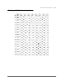
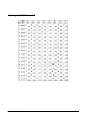
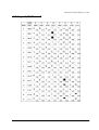
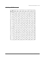
Appendix C Character Code Tables
Page 0 (PC437: USA, Standard Europe) . . . . . . . . . . . . . . . . . . . . . . . . . . . . . 1
Page 1 (Katakana) . . . . . . . . . . . . . . . . . . . . . . . . . . . . . . . . . . . . . . . . . . . . . . 2
Page 2 (PC850: Multilingual) . . . . . . . . . . . . . . . . . . . . . . . . . . . . . . . . . . . . . . . 3
Page 3 (PC860: Portuguese) . . . . . . . . . . . . . . . . . . . . . . . . . . . . . . . . . . . . . . . 4
Page 4 (PC863: Canadian-French) . . . . . . . . . . . . . . . . . . . . . . . . . . . . . . . . . 5
Page 5 (PC865: Nordic) . . . . . . . . . . . . . . . . . . . . . . . . . . . . . . . . . . . . . . . . . . . 6
Page 16 (WPC1252) . . . . . . . . . . . . . . . . . . . . . . . . . . . . . . . . . . . . . . . . . . . . . . 7
Page 17 (PC866: Cyrillic #2) . . . . . . . . . . . . . . . . . . . . . . . . . . . . . . . . . . . . . . . 8
Page 18 (PC852: Latin2) . . . . . . . . . . . . . . . . . . . . . . . . . . . . . . . . . . . . . . . . . . 9
Page 19 (PC858: Euro) . . . . . . . . . . . . . . . . . . . . . . . . . . . . . . . . . . . . . . . . . . . . 10
Page 255 (Blank page) . . . . . . . . . . . . . . . . . . . . . . . . . . . . . . . . . . . . . . . . . . . 11
International Character Sets . . . . . . . . . . . . . . . . . . . . . . . . . . . . . . . . . . . . . . 12
Appendix D System Planning
Control Method . . . . . . . . . . . . . . . . . . . . . . . . . . . . . . . . . . . . . . . . . . . . . . . . . 1
Windows Driver (EPSON Advanced Printer Driver) . . . . . . . . . . . . . . . . . 1
General Features of the EPSON Advanced Printer Driver . . . . . . . . 1
EPSON Advanced Printer Driver Components . . . . . . . . . . . . . . . . . 2
EPSON Advanced Printer Driver Support Environment . . . . . . . . . . 2
EPSON OPOS ADK . . . . . . . . . . . . . . . . . . . . . . . . . . . . . . . . . . . . . . . . . . . . 3
General Features of EPSON OPOS ADK (OPOS Control) . . . . . . . . . 3
EPSON OPOS ADK Contents . . . . . . . . . . . . . . . . . . . . . . . . . . . . . . . . 4
EPSON OPOS ADK Supported Environment . . . . . . . . . . . . . . . . . . . . 4
ESC/POS Command . . . . . . . . . . . . . . . . . . . . . . . . . . . . . . . . . . . . . . . . . . 5
How to Get a Driver . . . . . . . . . . . . . . . . . . . . . . . . . . . . . . . . . . . . . . . . . . 5
Appendix E FAQ
Can I use the TM-P60 in the Ad-Hoc mode? . . . . . . . . . . . . . . . . . . . . . . 1
Buzzer sounds when the TM-P60 is turned on. What should I do? . . . . . 1
How to set the buzzer not to sound. . . . . . . . . . . . . . . . . . . . . . . . . . . . . . 1
BATT LED lights or flashes. What should I do? . . . . . . . . . . . . . . . . . . . . . . 1
The Power LED is flashing slowly. What should I do? . . . . . . . . . . . . . . . . 2
The TM-P60 can’t connect to the Wireless LAN. What should I do? . . . 2
Rev. D
xv
Wireless LAN parameters for the TM-P60 cannot be set with RS-232 . .
Searching on the network takes several minutes. . . . . . . . . . . . . . . . . .
Network is disconnected several minutes after it is connected. . . . . .
TM-P60 turns off several minutes after it is turned on. . . . . . . . . . . . . . . .
Printing is not possible. . . . . . . . . . . . . . . . . . . . . . . . . . . . . . . . . . . . . . . . .
3
3
3
4
4
Appendix F Wireless LAN Network Composition
Network mode . . . . . . . . . . . . . . . . . . . . . . . . . . . . . . . . . . . . . . . . . . . . . . . . . .
Infrastructure Mode . . . . . . . . . . . . . . . . . . . . . . . . . . . . . . . . . . . . . . . . . .
Ad Hoc Mode . . . . . . . . . . . . . . . . . . . . . . . . . . . . . . . . . . . . . . . . . . . . . . .
Wireless LAN Use . . . . . . . . . . . . . . . . . . . . . . . . . . . . . . . . . . . . . . . . . . . . . . . .
Wireless LAN Security . . . . . . . . . . . . . . . . . . . . . . . . . . . . . . . . . . . . . . . . . . . . .
Security of a wireless LAN . . . . . . . . . . . . . . . . . . . . . . . . . . . . . . . . . . . . .
Security Function Outline . . . . . . . . . . . . . . . . . . . . . . . . . . . . . . . . . . . . . .
Outline of Each Security Function . . . . . . . . . . . . . . . . . . . . . . . . . . . . . .
xvi
1
1
1
1
2
2
2
2
Rev. D
TM-P60 Technical Reference Guide
Chapter 1
General Information
1.1 Features
The TM-P60 is a POS printer designed to meet the needs of both retail and hospitality for highspeed, on-the-go thermal printing.
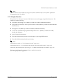
1.1.1 General
❏ Compact size with rugged design to ensure top reliablility
❏ Support for 802.11b wireless LAN protocols
❏ Belt clip for maximum mobility
❏ Industry-leading 12-hour battery life. (When power management is enabled)
1.1.2 Printer handling
❏ Drop-in paper loading and autocutter for easy use
1.1.3 Printing
❏ Clear, crisp high speed thermal receipt printing
1.1.4 Software
❏ Command protocol is based on the ESC/POS proprietary command system.
❏ OPOS ADK and Windows printer driver are available.
❏ Automatic status back (ASB) function that automatically transmits changes in printer status.
❏ Current TM-T88 series applications are instantly compatible with the printer
Rev. D
General Information 1-1
1.2 Product Structure
1.2.1 Standard Parts Included with the Printer
This printer is packed with the materials listed below.
❏ User’s Manual
❏ Roll paper: 1 roll
❏ Battery pack unit (LIP-2500), and its User’s manual: 1
❏ AC adapter (included only with some models): 1
Note:
To charge the battery, you have to use “PS-10” (AC adapter) or “OT-CH60” (Rapid battery charger).
Both are options.
1-2 General Information
Rev. D
TM-P60 Technical Reference Guide
1.2.2 Related materials for TM-P60
TM-P60 has the related materials listed in the following table.
Category
Name
Description
PS-10
This is an exclusive AC adapter for battery charging. It is able to
connect to TM-P60 directly.
The charging period: 4 hours.
OT-CH60
This is an exclusive battery charger. To use it you must take the
battery out of the TM-P60.
The charging period: 2.5 hours.
OT-RS60
This is to connect TM-P60 and host PC with serial connection.
LIP-2500
This is a spare battery. It is the as same as ithe ncluded one.
Options
OT-ST60
This is a shoulder strap.
Consumables
Roll Paper
This is required to print.
User’s Manual
This manual is packed in the carton box.
Technical Reference Guide
This Manual.
FAQ about ESC/POS
command
This Manual is Quick Reference of ESC/POS command with a
simple sample program & Tips.
ESC/POS Application
Programming Guide
This Manual is a Command Reference Guide of ESC/POS
command, including some sample programs & Tips.
Command Comparison
between the TM-T88II/T88III
and the TM-P60
This provides detailed command comparison information
among the printers.
OPOS ADK
This provides the OCX driver which is based upon OPOS. It has
manuals, sample programs, and TMFlogo utility.
Advanced Printer Driver
This is a Windows Driver. This Driver has a manual, sample
programs, and utilities to use the driver.
Memory Switch setting
Utility
This is a utility to adjust the setting (Memory Switch) of this printer.
See “2.5.3 Memory Switches” (page 2-11) for details.
TMFlogo
This is a utility to store “NV graphics“ into this printer. It helps
printing “NV graphics.”
TMNetWinConfig Ver. 2.0
This is a utility to set the wireless LAN property.
Manuals
Drivers
(WIndows
environment)
Utilities
(Windows
environment)
Please contact your dealer to get these.
1.3 Consumables
1.3.1 Roll paper
Roll paper widths are 60 mm and 58 mm {2.36"/2.28"}.
Note:
When you use 60mm width roll paper, you have to change the printer setting. See “2.5.4 Adjusting Roll
paper width” (page 2-13)
Rev. D
General Information 1-3
1.4 Product Specifications Overview
Print method
Print density
Printing width (default)
Font
Characters per
line (default)
Character size
(W × H)
Print font
Character set
Roll paper
dimensions
(default)
Paper thickness
Paper roll spool
diameter
Thermal line printing
203 dpi × 203 dpi [dpi: dots per 25.4 mm (dots per inch)]
52.5 mm, 420 dot positions
Font A: 12 × 24, Font B: 10 × 24, Font C: 8 × 16
Font A: 35, Font B: 42, Font C: 52
Font A: 1.50 × 3.0, Font B: 1.25 × 3.0, Font C: 1.0 × 2.0
95 Alphanumeric, 48 International, 128 × 10 Graphic
57.5 ± 0.5 mm
(59.5 ± 0.5 mm by removing the spacer installed)
50 µm ~ 80 µm
18 mm outside
Original: Kanzaki Specialty Paper (USA):
P350 (paper thickness: 62 µm)
Specified thermal P310 (paper thickness: 58 µm)
Paper
paper
P300 (paper thickness: 56 µm)
Maximum 70 mm/s, when number of dots per dot line is 64 dots or
less (printing with a fully charged battery, at 25°C, print density
Print speed
100%)
Interface
IEEE802.11b, RS-232
Receive buffer
128 bytes
Lithium-ion battery: Product name: LIP-2500, Trade name: Seiko
Epson Corporation
Output: DC 7.4 V
Specified battery Capacity: 2200 mAh
Output voltage: DC 12 V
Power
AC adapter
Input voltage: AC 100 V ~ 240 V
consumption (option)
Product name: PS-10, Trade name: Seiko Epson Corporation
Mechanism
10,000,000 lines printing
Print head
100,000,000 dots
Life
Autocutter
500,000 cuts
Operation
5 ~ 45°C, 10 ~ 90% RH
(Printing quality
guaranteed)
Abnormal operations not found when the printer is left under the
environment of 25°C, 60% RH for 2 hours after it was left in the
following conditions:
High temperature and humidity: 50°C, 90% RH for 120 hours
Temperature
High temperature: 70°C for 120 hours
/humidity
Storage
Low temperature: -25°C for 120 hours
Overall dimensions (mm)
103 × 159 × 65 (W × D × H)
Mass (approx.)
670 g (including LIP-2500 [battery pack] but not roll paper)
1-4 General Information
Rev. D
TM-P60 Technical Reference Guide
Chapter 2
Setup
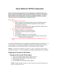
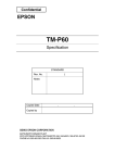
2.1 Part Name and Basic Operation
2.1.1 Part names
RS232C I/F
connecter cover
control
panel
roll paper
cover
open
button
connector for AC
adapter (option)
clip
battery cover
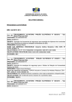
2.1.2 Control Panel
The control panel is shown below.
POWER
button
FEED
button
POWER
LED
Rev. D
ERROR
LED
BATT.
LED
Setup 2-1
❏ POWER LED
❏ ERROR LED
❏ BATT. LED
❏ FEED button
2.1.2.1 LED
POWER
POWER LED
Meaning
On
Power is on.
Off
Power is off.
Flashing
The printer is in power-off operation or is in an area where wireless communication is not possible.
ERROR
Printer Condition
ERROR LED
Meaning
Power On
On
Printer is offline (paper out, power-on initialization, roll paper
cover open, power-off operation, or the remaining battery
charge is not enough for printer operation when the battery is
used to supply the power.)
Off
Printer is online.
Flashing
It indicates an error. See “3.1 LED Blinking Pattern” (page 3-1) for
troubleshooting
On
Indicates that an abnormality occurred during battery
charging. The battery must be replaced with a new one.
Off
No problem.
Printer Condition
BATT. LED
Meaning
Power On without AC adapter
On
Remaining battery charge is not enough. It must be charged.
Off
Remaining battery charge is adequate.
Flashing
Remaining battery charge is below half.
On
The battery is being charged.
Off
The battery is fully charged.
Power Off, battery installed, and
AC adapter connected
BATT.
Power Off and battery installed
2.1.2.2 Control Panel Buttons
The control panel has a FEED button that you may have to use, although most paper handling
functions will be handled by your software.
FEED
Use this button to feed roll paper or to start a roll paper self test, or start printing status sheet.
( See “3.5.1 Self test mode” on page 3-3.)
2-2 Setup
Rev. D
TM-P60 Technical Reference Guide
Note:
The FEED button can be disabled by using an ESC/POS command. Refer to “ESC/POS Application
Programming Guide” for details.
2.1.3 Beeper Function
This printer has a “beeper“ function. This function causes beeping in specified situations. The
situations are the following:
❏ The battery remaining is low (Memory switch can enable/disable this function)
❏ The printer can’t find any Access point (wireless LAN). (Memory switch can enable/disable
this function)
❏ Roll paper is out (Memory switch can enable/disable this function)
❏ A error has occurred except “printer temperature error.“ (Memory switch can enable/
disable this function)
❏ Start of status sheet printing
❏ The radio field intensity check is started (reply for pressing FEED button)
❏ The radio field intensity check is processing
Note:
About memory switch, see “2.5.3 Memory Switches” (page 2-11).
About status sheet, see “2.6.2 Confirming the current LAN setting of the printer” (page 2-15).
About radio field intensity check processing, see “3.6 Radio Field Intensity Check Mode” (page 3-5).
The beeper can be beeped by a command from an application program.
See “4.3 Beeper function” (page 4-3)
Rev. D
Setup 2-3
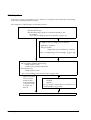
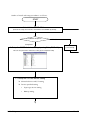
2.2 Setup Flow
You have to set up your printer to use it. And you can adjust some features by customizing
them. This section describes the setup.
The setup flow of preparing to use printer is below.
1. Printer setup
❏ Install Roll Paper
❏ Install the battery pack or connect the printer to the
AC adapter
(See “2.4 Providing power to the printer” (page 2-8))
2. Adjust various settings (If you need to)
❏ Memory switches
❏ Paper width
(Adjust the spacer & Memory switches)
(See “2.5 Adjusting Various Settings” (page 2-10))
3. Install to your wireless LAN by either method.
❏ Using utility (TMNet WinConfig)
• with wireless LAN
• with serial connection (RS 232C
❏ Using browser
• with wireless LAN
(See “2.6 Installing your wireless LAN” (page 2-14))
When you select
Direct control
method (ESC/
POS command,)
you don’t need
to install any
drivers.
4. Driver setup
❏ OPOS
❏ APD
(See “2.7 Install a Printer Driver in the Host PC
/ POS Terminal,” page 2-25)
5. Complete setup
2-4 Setup
Rev. D
TM-P60 Technical Reference Guide
Note:
A printer may beep when turned on. It is caused by the Access point’s LAN setting not corresponding to
the printer. Ignore the beeping. (see “3.2.1 Beeping Types” (page 3-2) for the beeping pattern.)
When you use OPOS (OCX driver from EPSON) or the Advanced Printer Driver, you need to install the
driver. When you use ESC/POS commands, you don’t have to install drivers. For information on these
drivers, see “D.1 Control Method” (page D-1).
The following sections describe the setup.
Rev. D
Setup 2-5
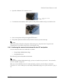
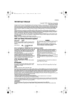
2.3 Installing/Replacing the Roll Paper
1. Press the button to open the roll paper cover.
2. Remove the used roll paper core if there is one, and
insert the new roll paper.
Note:
Note the direction the paper comes off the roll.
Do not use paper rolls that have the paper glued to the core.
3. Pull out some paper, close the cover, and tear off the
paper with the manual cutter.
CAUTION:
Be sure to use roll paper that meets the specifications.
Be sure not to touch the manual cutter. Otherwise your fingers might be injured.
Note:
Do not open the roll paper cover during printing or paper feeding. It may cause to make damage for
printer.
2.3.1 Installing or Replacing Roll Paper Vertically
You can hang the printer vertically on a belt using a clip on the back of the printer or a neck strap
provided as an option. When you use the printer vertically, follow the steps below to install roll
paper.
1. Press the button to open the roll paper cover.
2. Remove the used roll paper core if there is one.
2-6 Setup
Rev. D
TM-P60 Technical Reference Guide
3. Set the new roll paper on the inside of the roll paper cover.
Note:
Note the direction the paper comes off the roll.
4. Pull the leading edge of the roll
paper.
5. Align the left edge of the roll paper
with the edge of the cover.
6. Close the cover and tear off the paper
with the manual cutter.
Rev. D
Setup 2-7
2.4 Providing power to the printer
You can supply power through the battery pack packaged with the printer or the AC adapter
provided as an option.
WARNING:
Be sure to use the battery that came with the printer. Using a battery other than the one
specified may cause fire, explosion, leakage, overheating, or other damage.
2.4.1 Provide power from the battery
2.4.1.1 Installing the battery
CAUTION:
There is a risk of explosion if the battery is replaced by an incorrect type. Dispose of used
batteries according to the instructions.
1. Slide the battery cover to open it.
2. Install the battery.
3. Close the cover.
2-8 Setup
Rev. D
TM-P60 Technical Reference Guide
2.4.1.2 Charging the battery
When you charge the battery, you have a choice of two methods.
❏ Charge the battery using the exclusive battery charger (option: OT-CH60).
In this method, remove the empty battery from printer; then put it onto a battery charger.
For the battery charger operation, see the user’s manual of the battery charger.
This method requires about 2.5 hours to charge the battery.
❏ Charge the battery from the AC adapter (option: PS-10).
For this method, turn off the printer. Then connect the AC adapter into the printer’s
connector for AC adapter. (For instructions, see “2.4.2.1 Connecting the AC adapter” (page
2-9).) During the charging, the BATT. LED comes on (color: red). When the charging is
completed, the BATT. LED goes off.
This method requires about 4 hours to charge the battery.This method also requires the
printer’s power to be turned off. If the power is turned on, the battery is not charged; the
power is consumed to drive the printer.
2.4.2 Providing power from the AC adapter unit
When you would like to drive the printer with AC adapter (it is an option), read following
section.
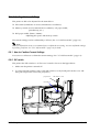
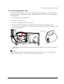
2.4.2.1 Connecting the AC adapter
1. Turn off the printer.
2. Connect the AC adapter into the connector as shown following figure.
connector for AC adapter
(It is covered by a cap)
Connect AC adapter to here opening the cap
WARNING:
Make sure you use the EPSON PS-10 AC adapter or equivalent.
Using an incorrect AC adapter may cause fire or electrical shock.
Rev. D
Setup 2-9
2.5 Adjusting Various Settings
This printer is able to be adjusted for the items below:
❏ DIP switch (handshake of serial communication conditions)
❏ Memory switch (serial communication conditions, roll paper width,
print density, etc...)
❏ Roll paper width (58mm / 60mm)
Adjusting the spacer and memory switch
The current settings can be confirmed by a self test. (See “3.5.1 Self test mode” (page 3-3).)
Note:
When you adjust these items, we recommend you to confirm the new setting. You can confirm the settings
by running a self-test. See “3.5.1 Self test mode” (page 3-3) for detail.
2.5.1 How to Confirm Current Settings
You can use a self-test to confirm the current settings. See “3.5.1 Self test mode” (page 3-3).
2.5.2 DIP switch
This printer has DIP switches 1~4. These are located as shown in the figure below.
1. Make sure the printer is turned off.
2. To access the DIP switches, remove the DIP switch cover by hand (pull out the cover and
then pull it upward to release the projection.)
projection
DIP switch cover
DIP switch
2-10 Setup
Rev. D
TM-P60 Technical Reference Guide
DIP switch
Handshake
DSW1
DSW2
DSW3
DSW4
DTR/DSR
OFF
ON
OFF
ON
RTS/CTS
OFF
OFF
ON
OFF
DSW 1 is fixed to OFF.
Note:
Serial communication setting is assigned to MemorySwitch (baud rate, parity). See the table “ Customize
values” (page 2-12) for details.
3. After set the DIP switch, attach the DIP switch cover.
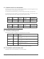
2.5.3 Memory Switches
This printer has a set of software switches called “Memory switches“ . The memory switch set
has “Msw 8,” “Customize value,” “Serial communication condition.”
The “Memory switch setting utility” can change the Memory switch set to ON or OFF as shown
in the table below:
Note:
When you use this printer with RS-232C interface, you should adjust the “serial communication setting“
(see the table “ Serial communication” (page 2-12).)
The Memory switch can be changed by either one of two methods:
• Memory switch setting utility
• Control by an ESC/POS command
Settings of the memory switch are stored in the NV memory; therefore, even if the printer is turned off, the
settings are maintained. Excessive use of this function may destroy the NV memory. As a guideline, do
not use this function more than 10 times a day.
When you use OPOS or APD, generally you don’t need to adjust memory switch because OPOS or APD
are able to set these items automatically.
Memory Switch 8
SW
Function
1
Status notice *1
Transmit s*
Doesn’t transmit
2
Beeper tone when the battery is not
charged
Beeps *
Doesn’t beep
3
Beeper tone when this printer can’t
connect to any access point
Beeps *
Doesn’t beep
4
Beeper tone when roll paper is out
Beeps *
Doesn’t beep
5
Beeper tone when an error occurs
Beeps *
Doesn’t beep
-
Fixed to Off *
6 ~ 8 Reserved
* : Default setting
Rev. D
On
Off
Setup 2-11
Note:
Msw 8-1:
When On is selected, this printer transmits power-off notice, power-on notice, and battery status to a host
PC. When off is selected, this printer doesn’t transmit these.
Msw 8-2:
When On is selected, the printer beeps the buzzer for 10 seconds when the battery status enters “battery
level is L“ or “battery level is S.“
Msw 8-3, 8-4, 8-5:
When On is selected, the buzzer beeps for 10 seconds for each situation. For information on printer errors
(Msw 8-5), see “3.1.1 Error Types” (page 3-1).
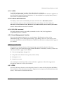
Customize values
Function
Selectable value
Roll paper width
58mm or 60 mm (Default: 58mm)
Time for auto power off
Disable, or 1 ~ 60 minutes (Default: 20 minutes)
Print density
70%, 75%, 80%, 85%, 90%, 95%, 100%, 105%, 110%, 115%, 120%,
125%, 130%, (Default: 100%)
* “Time for auto power off”: When a printer isn’t received any data from host PC, and isn’t operated anything (ex.
opening the roll paper cover, pressing the FEED button) during the specified time, the printer turns off itself
automaticaly.
Note:
See “2.5.4 Adjusting Roll paper width” (page 2-13) also to adjust roll paper width.
Serial communication
Function
Baud rate
Selectable value
9600 bps
19200 bps (default)
384000 bps
Parity
None (default)
Odd
Even
Note:
When this printer connected with serial interface, the data length is always “8 bit.“ The handshake is
changed by a DIP switch; see “2.5.2 DIP switch” (page 2-10) for details.
2-12 Setup
Rev. D
TM-P60 Technical Reference Guide
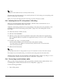
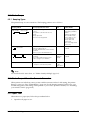
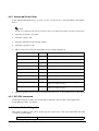
2.5.4 Adjusting Roll paper width
The TM-P60 accommodates 58 mm {2.28"}, and 60 mm {2.36"} wide paper rolls. The roll paper
guide is removed to change the roll paper width to 60mm. The method of removing the guide is
following below.
1. Make sure the power is turned off.
2. Open the roll paper cover.
3. Take the roll paper guide off of the printer.
4. Release th hook to the direction (j in the illustration) by using a pointed tool, such as
tweezers or a small screwdriver, and lift up (k in the illustration) the roll paper guide to take
the roll paper guide off.
roll paper guide
k
j
hook
5. Set the memory switch (customize value) for the paper width. (See “2.5.3 Memory Switches”
(page 2-11))
Note:
When this printer connected with serial interface, the data length is always “8 bit.“ The handshake is
changed by a DIP switch; see “2.5.2 DIP switch” (page 2-10) for details.
Rev. D
Setup 2-13
2.6 Installing your wireless LAN
Adjust TM-P60 for acutual wirelss LAN
Connect a trial host PC to TM-P60
This section describes how to install a wireless LAN in this printer. The following shows you the
installation procedure.
“2.6.1 Preparing a host PC for setting up a printer,” (page 2-15)
When you set up
printer using
wireless LAN.
When you set up
printer using
serial interface.
“2.6.2 Confirming the current
LAN setting of the printer,”
(page 2-15)
“2.6.3 Adjusting the host PC to
the printer’s LAN setting,”
(page 2-16)
“2.6.4 Connecting a serial
interface cable,” (page 216)
“2.6.5 Confirming the connection between the host PC and printer” (page 2-17)
Adjust the printer LAN
setting for your wireless
LAN (using web browser)
(“2.6.6.2 When you use a
browser for setup,”
page 2-23 )
Adjust the printer LAN setting for your
wireless LAN (using utility)
(“2.6.6.1 When you use the utility
(TMNetWinConfig) to set up” (page 2-20))
“2.6.7 Confirm the connection between your LAN and printer” (page 2-25)
Installation is complete
2-14 Setup
Rev. D
TM-P60 Technical Reference Guide
Note:
For detailed information about the utility and web browser for LAN setting,
see “ Wireless LAN Setup Detailed Information” (page B-1).
2.6.1 Preparing a host PC for setting up a printer
At first, prepare a PC (trial host PC) to set up a printer. The requirements for the trial host PC are
the following:
❏ OS:
Windows 2000 professional, Windows XP professional
❏ Communication port: 802.11b or serial port equipped
When you use the utility (TM Net Win Config Ver. 2.00 or later), you should install it in the host
PC before setting up the TM-P60. See “B.2.1 Install” (page B-4) for the installation procedure.
Note:
When you set up the printer by using wireless LAN, the LAN setting of host PC is changed to correspond
to the LAN setting of TM-P60 temporarily.
Required items
(wireless LAN items)
There are three way for instaling TM-P60 to wireless LAN. The following table lists required setting item
for trial host PC.
Using Brawser
Using TM Net Win Config
(in wireless LAN)
Using TM Net Win Config
(with serial interface (RS-232C))
Networkmode
(commucication mode)
Networkmode
(commucication mode)
“not required to change any
network items ”
SSID
SSID
WEP key
WEP key
IP address
IP address
Subnet mask
Subnet mask
(On the utility, you have to
select serial I/F communication
condition)
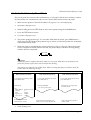
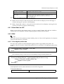
2.6.2 Confirming the current LAN setting of the printer
Confirm the current LAN setting of the printer according following procedure.
1. Turn on the printer’ s power.
2. Open the roll paper cover.
3. Press the FEED button until the printer beeps (about 2 seconds).
4. Close the roll paper cover.
5. The printer prints the current LAN setting (Status sheet).
Rev. D
Setup 2-15
Note:
The printed result (Status sheet) is necessary at the next step.
The printer may beep when turned on. It is caused by the host PC’s LAN setting not corresponding to the
printer’s setting. Ignore the beeping.
When you connect serial cable (RS-232C) at turning on printer, this mode is disable.
2.6.3 Adjusting the host PC to the printer’s LAN setting
When you set up the printer with serial interface, omit this section and read from “2.6.4
Connecting a serial interface cable” (page 2-16).
Adjust the LAN setting of the host PC corresponding to the status sheet. (It is printed at “2.6.2
Confirming the current LAN setting of the printer” (page 2-15).) The setting items are the
following.
❏ Network mode (Ex: Ad-Hoc mode)
❏ SSID (Ex: EPSONNetIBSS)
❏ WEP (Ex: None) (This item isn’t printed on status sheet. This printer isn’t registered any
keys at shipped. When your printer isn’t registered any key, you have to set to “disabled”
this item.)
❏ IP address (Ex: Auto, or 192.168.192.XXX)
(Don’t set the IP address of host PC the same as the printer’s setting.
Ex; when printer’s IP address is 192.168.192.168, set the host PC’s to 192.168.192.2.
Don’t set 192.168.192.168)
❏ Subnet mask (Ex:0, 0, 0, 0)
Note:
For informatin about the PC setting method, see your PC’s manual or wireless LAN card’s manual.
The examples are for the default setting. You should use the settings printed on the status sheet.
After the setup, skip the “2.6.4 Connecting a serial interface cable” (page 2-16), and go to “2.6.5
Confirming the connection between the host PC and printer” (page 2-17).
2.6.4 Connecting a serial interface cable
When you don’t set up the printer with serial interface, omit this section and read from “2.6.5
Confirming the connection between the host PC and printer” (page 2-17).
Use the following procedure.
1. Turn off the printer.
2-16 Setup
Rev. D
TM-P60 Technical Reference Guide
2. Open the “RS232C I/F connecter cover.”
RS232C I/F connecter
cover
3. Connect the serial interface cable (option) to the printer and the serial port of the host PC.
4. Turn on the printer while pressing the FEED button.
5. The printer prints the self test result, which is necessary for the next step.
Note:
If you connect the serial cable to the printer while turning it on, the printer doesn’t support serial
communication. Turn off the printer before connectiing the cable.
2.6.5 Confirming the connection between the host PC and printer
You can select from these two methods to confirm:
•
Using Utility (TMNetWinConfig)
•
Using Web browser
The following sections describe each method.
Note:
Before you using Utility (TMNetWinConfig), you have to install it into your host PC. About install it,
See “B.2.1 Install” on page B-4.
When you connect TM-P60 to host PC with serial cable, you have to use the utility to confirm the
connection. See “2.6.5.1 When you use the Utility (TMNetWinConfig) to set up the connection” (page 218).
Rev. D
Setup 2-17
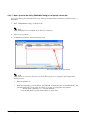
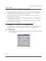
2.6.5.1 When you use the Utility (TMNetWinConfig) to set up the connection
You can confirm the connection this way when you select either connection (wireless LAN, or
RS-232C)
1. Run “TMNetWinConfig“ on the host PC.
Note:
If the utility hasn’t been installed on the host PC, install now.
2. Turn on your printer.
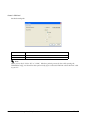
3. Confirm the printer is shown in the list view.
The your printer is shown in here.
Note:
If the printer isn’t shown in the list view, check following item. See Appendix B for details of the
utility function.
•
Turn the printer on.
•
Without connecting a serial cable to the TM-P60, confirm that the “Search Method,“ and
“Search Option IP“ are correct. You have to set it to correspond to the printer.
“Search Path“; Menu:Tool -> “Search Method.“
(You should check “Search Path selection: select All“)
2-18 Setup
Rev. D
TM-P60 Technical Reference Guide
“Search Option IP“; Menu:Tool -> “Search Option“ -> “IP“
(You should set the IP address and subnet mask to search.
See “ Search Options - IP” (page B-17) for details)
Search Method
Search Option IP
•
When you use serial cable, confirm connect a serial cable to the TM-P60 and host PC, and
turn the printer on again.
•
With connecting a serial cable to the TM-P60 and host PC, confirm that the “Search
Method,“ and “Search Option COM“ are correct. You have to set it to correspond to the
printer.
“Search Path“; Menu:Tool -> “Search Method.“ (You should check “Search Path
selection: select All“)
“Search Option COM“; Menu:Tool -> “Search Option” -> “COM.“
Search Method
Search Option COM
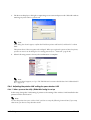
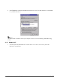
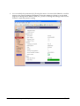
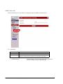
2.6.5.2 When you use a browser for setup
1. Start your Web browser (Ex. Internet Explorer)
2. Enter the IP address of the printer into the address bar, and press Enter key.
Note:
The IP address is printed at “2.6.2 Confirming the current LAN setting of the printer” (page 2-15).
Rev. D
Setup 2-19
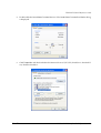
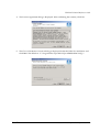
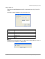
3. The browser displays a dialog box requesting a user name and password. Click OK without
entering any user name or password.
Note:
If the dialog box doesn’t appear, confirm the IP address (printer and host PC) and host PC’s subnet
mask.
This printer doesn’t have any password at shipped. When you registered a password into the printer,
you have to enter it on the dialog box. For setting password, see “ Password” (page B-41).
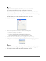
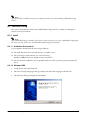
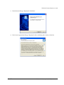
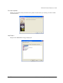
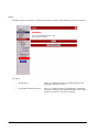
4. When following screen is shown, the confirmation is complete.
Note:
If the screen doesn’t appear, see “Q 6. The TM-P60 can’t connect to the Wireless LAN. What should I
do?” (page E-2).
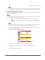
2.6.6 Adjusting the printer LAN setting for your wireless LAN
2.6.6.1 When you use the utility (TMNetWinConfig) to set up
In this step, change the LAN setting of printer to the setting of the wireless LAN installed in the
printer from the trial host PC.
Note:
To enter the printer into your wireless LAN, you have to setup the following items at least. If you setup
other items, you have to setup also these items.
2-20 Setup
Rev. D
TM-P60 Technical Reference Guide
•
•
•
•
Network mode (it is fixed to Infrastructure from utility accesses the printer.)
SSID
Method for specifying the IP address / IP address, subnet mask, default gateway
WEP key
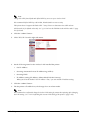
1. Select the printer from the list view.
Note:
When you use multiple TM-P60 printers, you can distinguish each TM-P60 with a MAC address.
The MAC address can be confirmed by the status sheet. See “2.6.2 Confirming the current LAN
setting of the printer” (page 2-15) about the status sheet.
Don’t turn off the printer until the step 9. If do so, the printer may be not able to comunicate the host
PC. In this case, reset the printer to default setting and try again the setting procedure.
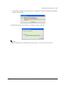
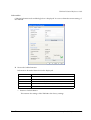
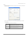
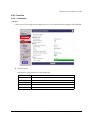
2. Click the “configuration“ button.
3. Click the “Wireless“ Tab
4. Set following items for the wireless LAN installed the printer.
Rev. D
•
Communication mode (Network mode): (Check to “Infrastructure.“ (If you don’t check
it, it is checked automaticaly))
•
SSID
•
WEP key, and active WEP key
Setup 2-21
Note:
Change the SSID from default and define WEP key to secure your wireless LAN.
We recommend to define WEP key as 128bit, Hexadecimal to secure security.
This printer doesn’t support the blank SSID ““(any). Enter one character into the SSID at least.
Ad-Hoc mode is for default value only. See “Q 1. Can I use the TM-P60 in the Ad-Hoc mode?” (page
E-1) for detail.
For detail of setting items, see “B.3 Setting Using a Web Browser” (page B-28).
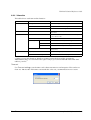
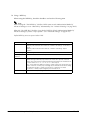
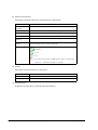
5. Click the “TCP/IP” tab.
6. Set the following items for the wireless LAN installed in the printer.
•
Method for specifying the IP address
•
IP address setting (IP address, Subnet Mask, Default gateway)
When you select the method “Auto,“ you can omit the IP address setting.
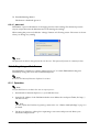
7. Click the “OK” button. (This utility shows a dialog box, follow the message.)
8. A dialog box is shown as following, click the OK button without entering any password.
Note:
This printer doesn’t have any password at shipped. When you registered a password into the printer,
you have to enter it on the dialog box. For setting password, see “B.2.4.1 password” (page B-28).
9. The changin is enabled after the utility shows you “finished” message.
2-22 Setup
Rev. D
TM-P60 Technical Reference Guide
Note:
We recommend to confirm the changed wireless LAN setting by status sheet printing after changing
the LAN setting. (see “2.6.2 Confirming the current LAN setting of the printer” (page 2-15))
2.6.6.2 When you use a browser for setup
In this step, change the LAN setting of printer to the setting of the wireless LAN installed in the
printer from the trial host PC.
Note:
To enter the printer into your wireless LAN, you have to setup the following items at least. If you setup
other items, you have to setup also these items.
•
•
•
•
Network mode (it is fixed to Infrastructure from utility accesses the printer.)
SSID
Method for specifying the IP address / IP address, subnet mask, default gateway
WEP key
Note:
Don’t turn off the printer until the step 8. If do so, the printer may be not able to comunicate the host
PC. In this case, reset the printer to default setting and try again the setting procedure.
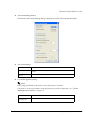
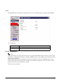
1. Open the screen with your web browser. (See “2.6.5.2 When you use a browser for setup”
(page 2-19) for this procedure).
2. Click “Wireless“ from the right side menu.
3. Set the following items for the wireless LAN installed in the printer.
Rev. D
•
Network mode (Communicaiton mode): (It is fixed to “Infrastructure“)
•
SSID
•
WEP key, and active WEP key
Setup 2-23
Note:
Change the SSID from default and define WEP key to secure your wireless LAN.
We recommend define WEP key with 128bit, Hexadecimal to secure security.
This printer doesn’t support the blank SSID ““(any). Enter one characters into SSID at least.
Ad-Hoc mode is for default value only. See “Q 1. Can I use the TM-P60 in the Ad-Hoc mode?” (page
E-1) for detail.
4. Click the “submit” button.
5. Click “TCP/IP“ from the right side menu.
6. Set the following items for the wireless LAN installed the printer.
•
Get IP Address
•
Set using Automatic Private IP Addressing (APIPA)
•
Set using PING
•
IP Address setting (IP address, Subnet Mask, Default Gateway)
When you select the method “Get IP Address: Auto,“ you can omit the IP address setting.
7. Click the “submit” button.
8. The the printer off and back on; the changes have now been made.
Note:
We recommend to confirm the changed wireless LAN setting by status sheet printing after changing
the LAN setting. (see “2.6.2 Confirming the current LAN setting of the printer” (page 2-15))
2-24 Setup
Rev. D
TM-P60 Technical Reference Guide
2.6.7 Confirm the connection between your LAN and printer
Transmit “ping” command to the printer from PC in the LAN to which the printer is connected
to confirm the connection. If a reply isn’t returned from the printer, retry these procedures from
the first after reset the wireless LANsetting of printer.
2.7 Install a Printer Driver in the Host PC / POS Terminal
EPSON provides printer drivers for the TM-P60. The drivers are OPOS and Advanced Printer
Driver (APD). They are for the Windows® environment.
2.7.1 OPOS
2.7.1.1 Installing and setting up
When you install and set up, please refer to the User's Manual, the file is automatically created
during the installation of the OPOS ADK.
Rev. D
Setup 2-25
Outline of install and setup procedure is as follows.
START
1. Installation OPOS ADK
(Execute the Setup.exe in DISK1, and continue to installation by wizard)
Is installation completed?
ERROR
Completed
2. Setup the OPOS & device setting by using SetupPOS utility
For detail refer to
[ User Manual]
You can setup the OPOS and device setting by the SetupPOS utility.
2.1 Setup the OPOS & device setting
❏ Select the device and I/F setting
❏ Device specified setting
2-26 Setup
•
Paper type & size setting
•
Bitmap setting
Rev. D
TM-P60 Technical Reference Guide
2.2. Device communication test by executing the CheckHealth
ResultCode
ERROR
SUCCESS
The OPOS and device settings are right.
&
The Install and Setup are completed.
Confirm the error condition by
referring to the [User's manual]
(3. Confirmation by sample program)
4. Make a OPOS compliant program
END
1. Installation.
Execute the Setup.exe in DISK. and continue to install by following the wizard instructions.
Rev. D
Setup 2-27
2. Set up the device and environment.
1. Set the device setting by using SetupPOS utility.
•
•
Select the device and I/F setting.
Device specified setting. (set the specified setting of the device)
2. Execute the CheckHealth
Device communication test.
•
•
If you get "SUCCESS", the setting of the device is right.
If you get ResultCode (error), re-check the device connection setting by following the
User's Manual.
After performing the above procedure, use an OPOS compliant program in your system.
Note:
Please refer to the sample program when you make a program.
The OPOS ADK provides a sample program for each device class. The sample programs are intended
as programs to serve as references for application developers. The ways to use the principal methods
and properties for each device are introduced in the form of Visual Basic and Visual C++ programs. In
this manual, it is introduced in the form of Visual Basic.
2.7.1.2 Package contents of EPSON OPOS ADK
Package contents of EPSON OPOS ADK are same as that of the previous one.
❏ Installer
❏ SetupPOS Utility
❏ OPOS Controls
❏ Manual
•
User’s Manual: Installation of the EPSON OPOS ADK, Configurations,and explanations
of the attached tools.
•
ADG : Detailed information on the each device to support the development.
ADG for General :
General information on the development.
ADG for Common Information :
Common information to all the devices.
ADG for device class :
General information on the device class.
ADG for model :
Specific explanation on the device.
Sample program :
Information on the Sample Programs.
❏ Sample Program
Sample program for VB and VC (for each device class)
2-28 Setup
Rev. D
TM-P60 Technical Reference Guide
2.7.2 Advanced Printer Driver (APD)
2.7.2.1 Installing and Setting Up
When you install and set up the APD, please refer to the “EPSON Advanced Printer Driver
Install Manual.“ The Manual is a PDF file, which is provided with other manuals for the APD.
Outline of installation and setup procedure is as follows.
1. Install EPSON Advanced Printer Driver
Select the modules needed to install:
TM-P60, Status API
2. Set up the printer port
3. Test print
1. Install EPSON Advanced Printer Driver
Execute the installer “ADT###e.exe,“ and select modules which you need. The
recommended modules are shown below. Refer to the installation manual for details.
EPSON TM-P60 Receipt
This module is required for printing.
Status API:
This module is required for monitoring the printer. This
module provides API to monitor the printer’s status.
Note:
For the Manual, Sample program, and each utility, you have to download separately the
ADT###e.exe.
2. Set up the printer port
After installing the APD, you need to adjust the printer port setting for the printer interface
model. See the Installation manual and the User’s manual for details.
3. Test print
Execute a test print from the “property” of the printer to confirm the setting. If the test print
is not correct, please see the “Notes” on the “User’s Manual” and “Status API Reference
Manual” to solve the your problem.
Note:
You can use the printer with sample program (written in Microsoft Visual Basic, Visual C++). The
sample program is provided separately.
Rev. D
Setup 2-29
2-30 Setup
Rev. D
TM-P60 Technical Reference Guide
Chapter 3
Troubleshooting
This section describes general troubleshooting.
3.1 LED Blinking Pattern
3.1.1 Error Types
The printer stops all printer operations, goes offline, and the ERROR LED blinks when an error
is detected.
ERROR LED Blinking Pattern
320 ms
ERROR
Description
Recovery
Printer temperature
error (*1)
The internal temperature
of the printer is extremely
high
Recovers automatically
when the printer cools
Autocutter error
The autocutter does not
work correctly
Recovers by error
recovery command.
(See “Paper Jam”
(page 3-2))
Circuit error
The circuit board doesn’t
work
Impossible to recover
Memory error
The printer does not work
correctly in R/W checking.
Impossible to recover
Voltage error
The power supply voltage
is extremely high or low
Impossible to recover
Software error
The firmware does not
work correctly.
Impossible to recover.
The radio unit error
The IEEE802.11b radio
interface unit doesn’t
work.
Impossible to recover
Note:
The ERROR LED is on when the printer is offline (paper out, power-on initialization, roll paper cover
open, power-off operation, or the remaining battery charge is not enough for printer operation when the
battery is used to supply the power.)
(* 1) Print temperature error is not an abnormality.
When you see an error described as “Impossible to recover“ in the recovery column, turn off the printer as
soon as possible and consult your dealer.
When the printer beeps, see also “Beeping Types” (page 3-2).
Rev. D
Troubleshooting 3-1
3.2 Printer Beeps
3.2.1 Beeping Types
The printer beeps in some situations. The beeping patterns are as follows.
Beeping
times
Switch method to
Enable/disable
• Battery remaining amount is “L level”
or less
• The printer can’t find an Access
point.
• Roll paper end
• An error has happened.
5 times
Memory switch specify
the beeping enable/
disable
• Battery remaining
amount [Msw 8-2]
• Can’t find Access
point [Msw 8-3]
• Roll paper end
[Msw 8-4]
• Error has happened
[Msw 8-5]
• A status sheet is printed (when you
press the FEED button)
• A radio field intensity check sheet is
printed.
(when you press the FEED button)
1 time
This beeping is always
enabled.
• A radio field intensity check sheet is
printed.
(See “Radio Field Intensity Check
Mode” (page 3-5) for details.)
Until
printing is
started.
This beeping is always
enabled.
• Application transmit
“beeper command“to printer.
Depends
on the
application
--
Beeping Pattern
The beeping indicates mean
1000 ms ON
1000 ms OFF
100 ms ON
100 ms ON
1900 ms OFF
Other patterns
Note:
For details about the status sheet, see “Status sheet printing” (page 3-4).
3.3 Printer Beeps When the Power is Turned on
When printer can’t find any access points with the current wireless LAN setting, the printer
beeps to warn you. [See “Printer Beeps” (page 3-2) for the beeping pattern.] In this case, you
should change the LAN setting of this printer or your access point. For details, see “Installing
your wireless LAN” (page 2-14).
3.4 Paper Jam
When there is a paper jam, follow the procedure below.
1. Open the roll paper cover.
3-2 Troubleshooting
Rev. D
TM-P60 Technical Reference Guide
2. Remove the jammed paper.
3. Close the roll paper cover.
4.
Transmit the error recovery command.
Note:
For error recovery command information, see the manual for each control method (OPOS, Advanced
Printer Driver, ESC/POS commmand).
3.5 To Confirm the Current Setting of the Printer
This printer has two functions to confirm the current setting of the printer.
❏ Self test mode
This mode prints all settings of the printer and a character printing test on roll paper.
(Ex: serial communication condition, wireless LAN setting, memory switch setting, etc...)
❏ Status sheet printing
This prints wireless LAN settings on roll paper.
3.5.1 Self test mode
The self test lets you know if your printer is operating properly. It checks the control circuits,
printer mechanisms, print quality, control software version, and DIP switch settings.
This test is independent of any other equipment or software, so it is a good idea that run it when
you first set up the printer and if you have any trouble. If the self test works correctly, the
problem is in the other equipment or the software, not the printer.
1. Make sure the printer is turned off and the roll paper cover is closed properly.
1. While holding down the FEED button, turn on the printer using the switch on the front of the
printer. The self test prints the printer settings and then prints the following, cuts the paper,
and pauses.
If you want to continue SELF-TEST printing, please press
FEED button.
1. Press the FEED button to continue printing. The printer prints a pattern using the built-in
character set.
Note:
If you would like to finish the test printing, turn off the power.
2. The self test automatically ends and cuts the paper after printing the following:
*** completed ***
Rev. D
Troubleshooting 3-3
The printer is ready to receive data as soon as it completes the self test.
Note:
If you want to pause the self test manually, press the FEED button. Press the FEED button again to
continue the self test.
3.5.2 Status sheet printing
The status sheet describes the wireless LAN setting of printer. This sheet is useful to confirm the
current wireless LAN status.
*** Dynamic Status Sheet ***
802.11b Interface
MAC Address
:00-10-c6-24-62-cc
Hard Version
:1.00
Soft Version
:0.83
WLAN Pri F/W :4.4.1
WLAN STA F/W :8.42.1
Allowed Channel :07ffh
Wireless Status
SSID :EpsonNetIBSS
Network Mode
:Ad-Hoc
Link Status
:Connect 1
Channel
:6
Transmission Rate :11Mbps
Access Point
:00-0a-79-26-fd-04
Signal Level
:-60dbm
Noise Level
:-85dbm
TCP/IP Status
IP Address
:192.168.198.168
Subnet mask
255.255.255.0
Default Gateway :0.0.0.0
A example of status sheet
To print a status sheet, follow the procedure below.
1. Make sure the printer is turned on. If it is off, turn it on.
1. Open the roll paper cover.
1. Press the FEED button until the printer beeps 1 time. (about 2 seconds).
1. Close the roll paper cover.
1. The printer prints the current LAN status (Status sheet), and then returns to the normal
mode.
Note:
After printing a status sheet, this printer doesn’t reset itself (keeps all setting values).
3-4 Troubleshooting
Rev. D
TM-P60 Technical Reference Guide
3.6 Radio Field Intensity Check Mode
This mode prints the current radio field intensity on roll paper. This mode is useful to confirm
that the printer can communicate with an access point at the current location by radio.
1. Make sure the printer is turned off and the roll paper cover is closed properly.
1. Open the roll paper cover.
2. While holding down the FEED button, turn on the printer using the POWER button.
3. Press the FEED button 2 times.
4. Close the roll paper cover.
5. The printer prints the message “To start radio field intensity check, press FEED button.“
Then press the FEED button; the printer beeps to inform you that the printer has started the
radio field intensity check
6. When the check is completed, the printer prints the result on roll paper. When the printer
cannot complete the check within 4 seconds, the printer beeps with the following timing
until the check is completed.
100 ms ON
1900 ms OFF
Note:
Usually the printer completes this check within 2 or 3 seconds. When there are too many access
points, the printer requires more time to compete the checking.
This feature isn’t supported in Ad-Hoc mode. When executing this feature in Ad-Hoc mode, the
printer prints the following message.
Radio Field Intensity Check
Radio Field Intensity Check
Radio Field Intensity Check
To start radio field intensity check,
To start radio field intensity check,
To start radio field intensity check,
press FEED button.
press FEED button.
press FEED button.
SSID: Planet
SSID:EpsonNetIBSS
No Access point found.
AP 1
MAC Address 00-a0-f8-a5-74-3f
Channel
11
WEP
Enable
Signal Level
-54dbm
Noise Level
-96dbm
Print example the check
when the test is success.
Print example when printer can’t
find any access point with the SSID
This feature is not supported
in Ad-Hoc mode.
Print example when printer is
Ad-Hoc mode.
7. Turn off the power.
Rev. D
Troubleshooting 3-5
3.6.1 Resetting the printer
Reset the printer’s LAN setting to be certain it is correct.
This mode is useful when you need to set the wireless LAN setting of a TM-P60 when the setting
cannot by changed by an Access point, serial cable, or TMNetWinconfig. In this case, reset the
printer to change the printer to Ad-Hoc mode for communication without any access point.
Note:
When you haven’t adjusted the printer’s wireless LAN setting, or you set up the printer with a serial
interface, you can omit the resetting. In this case, omit the resetting; then confirm the current setting.
The printer may beep when turned on. It is caused by the access point’s LAN setting not corresponding to
the printer’s setting. Ignore the beeping.
1. Open the roll paper cover.
2. Turn on the printer's power while pressing down the FEED button.
3. Press the FEED button 6 times.
4. Close the roll paper cover.
5. The printer prints the procedure for resetting. Follow the procedure. (Open the roll paper
cover, press the FEED button, close the roll paper cover.)
Then, the printer prints "Initialize" and cuts the paper, then starts resetting. Printer is rebooted
after the initialization.
Note:
This printer completes the initialization a few seconds after the paper is cut.
3.7 Hexadecimal Dump Mode
This feature allows experienced users to see exactly what data is coming to the printer. This can
be useful in finding software problems. When you turn on the hex dump function, the printer
prints all commands and other data in hexadecimal format, along with a guide section to help
you find specific commands.
To use the hex dump feature, follow these steps:
1. After you make sure the printer is off, open the roll paper cover.
2. While you hold down the FEED button, turn on the printer.
3. Close the cover.
3-6 Troubleshooting
Rev. D
TM-P60 Technical Reference Guide
4. Run any software program that sends data to the printer. The printer prints “Hexadecimal
Dump” and then all the codes it receives in a two-column format. The first column contains
the hexadecimal codes and the second column gives the ASCII characters that correspond to
the codes. Part of a hexadecimal dump is shown below:
Hexadecimal Dump
To terminate hexadecimal dump,press
FEED button three times.
1B 21 00 1B 26 02 40 40 40 40
. ! . . & . @ @ @ @
1B 25 01 1B 63 34 00 1B 00 1B
. % . . c 4 . . . .
41 42 43 44 45 46 47 48 41 42
A B C D E F G H A B
•
A period (.) is printed for each code that has no ASCII equivalent.
•
In hex dump mode all commands except real time ESC/POS commands are disabled.
5. Press the FEED button twice to print the last line.
6. Pressing the FEED button two times turns off the hex dump mode and returns the printer to
the normal mode. Or, reset the printer to turn off the hex dump mode.
Note:
The hexadecimal dump mode can’t be used with OPOS or the APD.
Rev. D
Troubleshooting 3-7
3-8 Troubleshooting
Rev. D
TM-P60 Technical Reference Guide
Chapter 4
Application Development Information
This section contains usable information to develop POS systems that use this printer.
4.1 About wireless communication
4.1.1 For Application developing
The TM-P60 uses wireless comunication technology; therefore temporary communication
breaks may occur when you move or are in an outside environment. When you develop
application software using wireless communication, you should consider this.
We recommend you confirm whether or not the printer printed after every print data
transmission unit. Detection of communication errors and recovering from such errors are also
important. Data communication without confirmation of printing and detetection of
communication errors may cause data loss.
To ensure heghly reliable data communication, we recommend the use of the status
confirmation function of our genuine OPOS, or Windows Printer Driver (APD).
4.1.2 For Radio field intensity
Wireless communication is related to radio field intensity. The TM-P60 has a function,“Radio
Field Intensity Check Mode” (page 3-5), to confirm the current radio field intensity. This mode
shows the current radio field intensity to the operator.
The function can’t be executed from any drivers (OPOS, Advanced Printer Driver) or ESC/POS
commands.
Rev. D
Application Development Information 4-1
4.1.3 Operation tested Access point products
The Access points that have been evaluated with the TM-P60 are in the following table. For the
latest information, see the appropriate web site below:
For customers from North America, go to the following web site: http://pos.epson.com/
For customers from other countries, go to the following web site: http://www.epson-pos.com/
Select the product name from the “Select any product” pull down menu.
.
Vendor
Model
A/P firmware
RF firmware
Power Managiment
funtion with TM-P60
Symbol
AP-4121-1150-US
0.252-13
V2.51-08
Impossible
Symbol
AP-4131-1050-WW
0.350-33
F3.10-04
Possible
Vender
Model
Software Ver.
Boot ver.
Power Managiment
funtion with TM-P60
Cisco
Air-AP1120B-A-K9
12.2 (13)JA1
12.2(8)JA
Impossible
4.2 About the Battery Remaining Amount
4.2.1 The battery remaining amount
This printer has a battery to supply power. The battery has four statuses:
Battery Status
The battery
LED condition
Level H (High)
Off
The remaining battery charge is between 100% and approximately
50% when the amount of difference between the full battery and
level L is 100%.
Level M
(Medium)
Flashing
The remaining battery charge is between approximately 50% and
level L when the amount of difference between the full battery and
level L is 100%.
Level L (low)
On
The battery needs to be replaced or recharged because the
remaining battery charge is low.
Level S (Serious)
On
The printer will not operate because the remaining battery charge
is too low.
Description
*When an AC adapter is connected to the printer, the “battery LED condition” is always Off.
4.2.2 The method to confirm the battery status
The battery status can be confirmed by every control method.
4-2 Application Development Information
Rev. D
TM-P60 Technical Reference Guide
4.2.2.1 OPOS
In OPOS, the battery status can be confirmed by Direct I/O method
“PTR_DI_GET_BATTERY_STATUS.” This information is described in the manual “Application
Developement Guide POS printer (TM Series): (4.3 StatusUpdateEvent regarding Battery Status.)”
This manual is installed with OPOS.
4.2.2.2 Advanced Printer Driver
The battery status can be confirmed by the Status API. The API is BiGetBatteryStatus.
Also, the battery status can be transmitted when the status changes. For this setting, use
BiSetBatteryStatusBackFunctionEx, BiSetBatteryStatusBackWndEx, BiCancelBatteryStatusBack.
See the “Status API user’s manual“ for details.
4.2.2.3 ESC/POS command
The beeper function can be operated by commands. See the “ESC/POS Application
Programming Guide“ for details.
4.2.3 Power Management function
The power management function is to save the battery. This function can be set from
TMNetWinconfig [“Power Management Setting” (page B-25)]. However, some Access points
don’t’t use this function with the TM-P60. See “Operation tested Access point products” (page 42) for details.
4.3 Beeper function
This printer has a beeper function. The beeper beeps automatically when the following
conditions occur. The automatic beeping enabled/disabled is switched by a memory switch. See
“Memory Switches” (page 2-11) for details.
❏ The remaining battery charge is low
❏ The printer can’t find an Access point (wireless LAN).
❏ Roll paper is out
❏ Printer has an error
Also, the beeper can be beeped by a command from an application. The following sections
describe the method for each control method.
4.3.1 OPOS
On OPOS, the beeper function can be beeped by Direct I/O method “PTR_DI_RING_BUZZER.”
This information is described in the manual “Application Development Guide POS printer (TM
Series.)” This manual is installed with OPOS.
Rev. D
Application Development Information 4-3
4.3.2 Advanced Printer Driver
In the Advanced Printer Driver, you have to use “Control font A.” The procedure is described
below.
Note
See the user’s manual of the Advanced Printer driver for detail of the utility “EPSON Control font.“
1. Open the properties of printer.
2. Click the “utility“ tab.
3. Click the “EPSON Control FontA“ button.
4. Click the “operation“ tab.
5. Edit a control font. The following table shows example definitions.
Deined Command data
Tone
Description
1B284104003031010A
1280Hz
1000ms beeping
1B284104003032010A
4100Hz
1000ms beeping
1B284104003033010A
1280Hz
200ms beeping
1B284104003034010A
4100Hz
200ms beeping
1B284104003035010A
1280Hz
200ms beeping -> 200ms off -> 200ms beeping
1B284104003036010A
4100Hz
200ms beeping -> 200ms off -> 200ms beeping
1B284104003037010A
1280Hz
500ms beeping
1B284104003038010A
4100Hz
500ms beeping
1B284104003039010A
1280Hz
200ms beeping -> 200ms off -> 200ms beeping ->
200ms off -> 200ms beeping
1B284104003039010A
4100Hz
200ms beeping -> 200ms off -> 200ms beeping ->
200ms off -> 200ms beeping
6. When the printer receives data of the defined control font A, the printer beeps as described.
4.3.3 ESC/POS command
The beeper function is able to be operated by commands. See the “ESC/POS Application
Programming Guide“ for details.
4.4 Various Status Categories
This printer is able to send various status reports to the host PC. This section describes the kind
of statuses and handling.
Status Categories
Description
4-4 Application Development Information
Rev. D
TM-P60 Technical Reference Guide
Roll Paper cover status
Roll paper cover is open or closed
FEED button status
Paper feed button is pressed or not
Error status
Various error information (Off-line / On-line), (detail of the error;
Mechanical error, autocutter error, auto-recovery error,
unrecoverable error)
The statuses are useful for the following situations.
❏ When an error status is sent to the host PC, the host PC can display an error message or
solution message for operator (with beeping).
❏ When “Paper end“ status is sent to the host PC, the host PC can display a message for the
operator to replace roll paper (with beeping).
4.4.1 Printer Status on APD
When you use APD to get printer’s status, you have to install “Status API“ and use it. Refer to
“Status API User’s Manual“ and the sample program of Status API for details.
4.4.2 OPOS
Note
This section describes the summary of status handling. Refer to “OPOS ADK Application Development
Guide General Functions” for details.
4.4.2.1 Checking the printer state
The state of the printer can be checked through properties supported by the printer. For
example, if the user wants to check if the printer cover is open, the CoverOpen property can be
used.
If OPOSPOSPrinter1.CoverOpen = True Then
MsgBox “Cover is open!”
End If
This and many other events can also be checked by firing a StatusUpdateEvent.
[Event management]
Private Sub OPOSPOSPrinter1_StatusUpdateEvent(ByVal Data As Long)
If Data = PTR_SUE_COVER_OPEN Then
MsgBox “Cover is open!”
End If
End Sub
StatusUpdateEvent can return information on the following items.
STATUS INFORMATION
PTR_SUE_COVER_OPEN
Rev. D
Cover is open.
Application Development Information 4-5
PTR_SUE_COVER_OK
Cover is closed.
PTR_SUE_REC_EMPTY
Receipt paper is out.
PTR_SUE_REC_PAPEROK
Receipt paper is OK.
PTR_SUE_IDLE
Printer State is idle.
When the FlagWhenIdle property is set to TRUE, PTR_SUE_IDLE is sent to inform the
application that the printer is idle. Other than when data is being sent, the printer is in an idle
state, so if FlagWhenIdle is TRUE, an event will be fired when printing is finished. After the
event is fired, FlagWhenIdle will be set to FALSE. By using this value, the information below can
be found out.
*Finding out when multiple asynchronous print jobs have finished printing. When multiple
asynchronous print jobs have been sent to the printer, it is possible to know when they have
finished printing. After setting the AsyncMode property to TRUE and running the PrintNormal
method, change the FlagWhenIdle property to TRUE. When all data has finished printing, the
printer becomes idle and a StatusUpdateEvent is fired to the application with the value of
PTR_SUE_IDLE.
4.4.2.2 Printer Errors and Status
A change in printer status when asynchronous data is being sent is made available to the
program by the firing of an ErrorEvent and StatusUpdateEvent. When the printer changes status
while nothing is happening, the change is told to the program by a StatusUpdateEvent only.
As an example, assume that the printer cover becomes open. Usually, when data is not being
sent to the printer and the cover is opened, a StatusUpdateEvent is fired to the application. After
the AsyncMode property is set to TRUE and a method is used to print data, if the cover is
opened while the data is being sent, the program is notified by an ErrorEvent. ErrorEvents are
fired when the error has interrupted the data that is being sent. Only StatusUpdateEvent will
fire when the error does not effect the data and the data will continue being sent as normal.
Reasons for the ErrorEvent being fired and the corresponding error names are listed below.
ResultCode/ ResultCodeExtended Reason
OPOS_E_ILLEGAL
There is an abnormality with the device. (Includes the
following 1 error)
OPOS_E_EXTENDED
Error determined by the device’s SO (Includes the
following 4 errors)
OPOS_EPTR_COVER_OPEN
Cover is open.
OPOS_EPTR_REC_EMPTY
Receipt paper is empty.
OPOS_E_FAILURE
Hard error (Includes the following 6 errors).
OPOS_EPTR_UNRECOVERABLE
Error that cannot be recovered from.
OPOS_EPTR_CUTTER
Error with the auto cutter.
OPOS_EPTR_MECHANICAL
Mechanical error.
4-6 Application Development Information
Rev. D
TM-P60 Technical Reference Guide
OPOS_EPTR_OVERHEAT
Head overheat error.
OPOS_EX_DEVBUSY
Device busy error.
OPOS_EPTR_REC_CARTRIDGE_REMOVED
Receipt cartridge is removed.
OPOS_EPTR_REC_CARTRIDGE_EMPTY
Receipt cartridge is empty.
OPOS_EPTR_REC_HEAD_CLEANING
Receipt head starts cleaning.
After an error occurs, more detailed information about the error can be obtained from the
ErrorLevel, ErrorStation, and ErrorString properties.
4.4.2.3 ESC/POS commands
When you use ESC/POS commands to control the printer, you can get the status by using
“status command” including Auto Status Back command (ASB.) Please refer to “ESC/POS
APG.”
4.5 NV memory
This printer has NV memory (Non-volatile). The data of NV memory remains after you turn off
the power. The NV memory is available in two ways.
1. NV Graphics
Please refer “NV Graphics Printing” (page 4-8) for details of the function.
2. User NV memory
There is free area in the NV memory that the user can use. You can use this free area for
notations, to write other character information, or for many other purposes. The data
remains after you turn off the power. Use ESC/POS commands to read and write this data.
The following are examples of purposes.
•
Date of the printer for maintenance
•
ID definition for developer or POS system
Note
When you use User NV memory area by using OPOS or APD, you have to use “Direct I/O method”
or “Control A font.” Please contact EPSON or your dealer for details.
Note the following when writing to and erasing NV memory.
❏ The following restrictions apply when performing NV memory operations (including data
writing and erasing).
Rev. D
•
The paper FEED button must not be used to feed paper.
•
The real-time command must not be executed.
Application Development Information 4-7
•
The ASB status will not be sent, even when the ASB function is set to enabled.
❏ The printer sometimes enters the Busy state while data is written to NV memory. It is
important not to send data from the host computer while the printer is in the Busy state, as it
will be incapable of processing any received data.
❏ Frequent use of the functions for writing to and erasing data from NV memory can damage
the memory. As a rule in using the various commands, avoid writing to NV memory more
than 10 times per day.
4.6 NV Graphics Printing
This printer has an “NV Bit-Graphics“ Function. This function provides printing Graphics (e.g. a
shop logo.) This function is available for any control method (APD, OPOS, ESC/POS
command.)
EPSON provides a utility, “TMFLogo,” that enables registration of a bitmap image in the NV
memory of an EPSON TM series printer. The bitmap image in the NV memory can be printed
with the printer by using each control method.
NV
Graphics
Printable Size
Printing method
<width>
Paper width, or
less than paper width.
Store
Store NV Graphics to NV memory by TMFLogo utility in device
specific settings on the SetupPOS utility. If you store the bitmap
in NVRAM, it is not necessary to restore it unless the NV memory
is deleted.
<height>
1200dot (normal mode)
2400dot (double-height mode)
Print
Depends on each control method.
Note
NV graphics data shares the domain used by user NV memory record data; therefore, the entire capacity of
the domain to which NV graphics data and user NV memory data are defined is targeted. The TM-P60’s
entire capacity is 384 KB.
Example: The NV memory can store 64 items graphics data when the file size of a graphic is 6 KB.
4.6.1 Advanced Printer Driver
4.6.1.1 How to print “NV Graphics“
APD prints a stored “NV Graphics“ by using “Control font.“ See the User’s Manual of the
Advanced Printer Driver for details.
4.6.1.2 Printable bitmap format in APD
The printable bitmap formats are formats that meet all the following condition.
❏ When using “NV Graphics“
•
Depends on the TM Flogo utility. (.BMP format)
4-8 Application Development Information
Rev. D
TM-P60 Technical Reference Guide
4.6.2 OPOS
EPSON OPOS ADK provides a tool, “TMFLogo” that enables registration of a bitmap image in
the NVRAM of an EPSON TM series printer. The tool can be used from the device specific
settings of the SetupPOS utility. The bitmap image in the NVRAM can be printed with a printer
by using the DirectIO method. Concerning the available NVRAM size for the TM-U220, refer to
the ADG for TM-U220 in the OPOS ADK.
4.6.2.1 Printing method
Print stored bitmap by DirectIO method.
•
*Command : PTR_DI_PRINT_FLASH_BITMAP
Note
NV graphics data shares the domain used by user NV memory record data; therefore, the entire capacity of
the domain to which NV graphics data and user NV memory data are defined is targeted. The TM-P60’s
entire capacity is 384 KB.
4.6.2.2 LetterQuality
It is possible to change the speed and quality of a bitmap by using the XXXLetterQuality
property.
RecLetterQuality = TRUE ‘print Receipt’s bitmap in quality mode.
RecLetterQuality = FALSE ‘print Receipt’s bitmap in speed mode.
4.6.2.3 Setting of printing position by escape sequence
POS Printers support escape sequences that can be treated as printing data. The following
commands are the escape sequence command for setting of printing position.
Name
Data
Remarks
Center
ESC |cA
Aligns following text in the center.
Right justify
ESC |rA
Aligns following text at the right.
Normal
ESC |N
Restores printer characteristics to
normal condition.
Note1: manner of ”ESC |cA” and “ESC |rA”
Characteristics are reset at the end of each print method or by a “Normal” sequence, so these escape
sequences cannot be used in the following manner.
OPOSPOSPrinter1.PrintNormal PTR_S_RECEIPT, Chr(&H1B) + ”|cA” + ”123”
OPOSPOSPrinter1.PrintNormal PTR_S_RECEIPT, “456” + Chr(13) + Chr(10)
The “123” characters will be printed in the center, but not under “456”. When using a new method to
print characters, it is necessary to add the desired escape sequence again.
Rev. D
Application Development Information 4-9
Note2 : limitation of ”ESC |cA” and “ESC |rA”
*During rotated printing mode (Left90, right90), these escape sequences will not work.
*These will not work if they are not the first character of a line.
*It is not possible to use these on PrintBitmap method.
4.6.2.4 Printable bitmap format in OPOS
The printable bitmap formats are formats that meet all the following conditions.
❏ BMP files
❏ Monochrome, 16-color (4 bit), 256-color (8 bit)
❏ Uncompressed
4.6.3 ESC/POS command
See “ESC/POS Application Programming Guide“ about the method.
4.6.4 Tips for Visual Basic
When programming with Visual Basic, limitations prevent data from 81h through 9Fh and from
E0h through FEh from being sent as characters. Therefore, you may be not able to print a part of
Page 0 (for example
)in Visual Basic.
However, you can use the following procedure to send this data.
Dim Send_ data(0) As Byte
Send_data(0) = &h81 ’1 byte of sending data
MSComm1.Output = Send_data
4-10 Application Development Information
Rev. D
TM-P60 Technical Reference Guide
Appendix A
The Difference Between TM-P60 and TM-T88II/III
TM-P60 is able to print with 42 print columns (when paper width is 58mm and Font B is printed
[default]). The number of print columns is the same as that of the TM-T88II/III (when paper
width is 80mm and Font A is printed [default].) Therefore,the TM-P60 is able to print with same
layout as TM-T88II/III.
This chapter is FAQ for the difference between the TM-P60 and the TM-T88III.
A.1 Can TM-P60 print with TM-T88II/III printer driver?
Unforunately, the answer is No. If you drive the TM-P60 with a TM-T88II/III printer driver
(OPOS, or Advanced Printer Driver), the printer doesn’t work correctly. You have to use a
printer driver for the TM-P60.
A.2 Can TM-P60 send back status to host PC the same as TM-T88II/III?
The answer is yes; however, the kind of status is little different between the TM-P60 and the
TM-T88II/III. The differences are shown in the following table.
Status name
TM-T88II/III
TM-P60
Comment
Drawer status
Supported.
Not supported
TM-P60 doesn’t have drawer kick out
connector.
Roll paper near end
Supported.
Not supported
TM-P60 doesn’t have near end detector.
Roll paper cover
open error
Supported.
Not supported
TM-P60 doesn’t have the error.
Battery remaining
amount
Not supported.
Supported
TM-T88II/III doesn’t have battery.
Rev. D
The Difference Between TM-P60 and TM-T88II/III A-1
A-2 The Difference Between TM-P60 and TM-T88II/III
Rev. D
TM-P60 Technical Reference Guide
Appendix B
Wireless LAN Setup Detailed Information
This appendix describes setting methods for wireless LAN. There are two methods: using
TMNetWinConfig (utility software), and using your web browser. To use either method, you
have to install the TCP/IP protocol into your operating system.
For instructions on installing TCP/IP protocol see “Setting the TCP/IP protocol in Your
Operating System” on page B-1.
For instructions on the wireless LAN setting of the TM-P60 using TMNetWinConfig (utility), see
“TMNetWinConfig” on page B-4.
For instructions on wireless LAN setting of the TM-P60 using your web browser see “Setting
Using a Web Browser” on page B-28.
B.1 Setting the TCP/IP protocol in Your Operating System
To set the IP address, you need to install the TCP/IP protocol in your operating system. How to
set the TCP/IP protocol is explained for Windows 2000 professional and Windows XP
professional.
B.1.1 Windows 2000
1. Double-click the Network and Dial Set Up icon in the Control Panel; then click Local Area
Connection Status.
Rev. D
Wireless LAN Setup Detailed Information B-1
2. Click Properties and check whether the Internet Protocol (TCP/IP) check box is checked. If
not, click the check box.
Note:
After the TCP/IP is installed, restart your computer and move on to the Installing TMNetWinConfig
section.
B.1.2 Windows XP
1. Click the Network and Internet Connections icon in the Control Panel; then click
Network Connections.
B-2 Wireless LAN Setup Detailed Information
Rev. D
TM-P60 Technical Reference Guide
2. Double-click the Local Area Connection icon. The Local Area Connection Status dialog
is displayed.
3. Click Properties and check whether the Internet Protocol (TCP/IP) check box is checked. If
not, click the check box.
Rev. D
Wireless LAN Setup Detailed Information B-3
Note:
After the TCP/IP is installed, restart your computer and move on to the Installing TMNetWinConfig
section.
B.2 TMNetWinConfig
This section describes the details of the TMNetWinConfig, which is a utility for setting up a
wireless LAN environment.
B.2.1 Install
Note:
After TMNetWinConfig is installed, if you add or remove protocols or services, TMNetWinConfig might
not work correctly. In this case, uninstall TMNetWinConfig and reinstall it.
B.2.1.1 Installation Environments
Your computer should meet the following conditions:
❏ The hard disk must have unused memory of 3 MB or more.
❏ The operating system must be one of the following:
Windows 2000 professional, Windows XP professional.
❏ The PC must be an IBM PC/AT compatible with one of the operating systems mentioned
above.
B.2.1.2 Windows 2000
1. Unzip the file and start Setup.exe.
2. The Choose Setup Language dialog is displayed. Select the language and click OK.
3. The Welcome dialog is displayed. Click Next.
B-4 Wireless LAN Setup Detailed Information
Rev. D
TM-P60 Technical Reference Guide
4. The License Agreement dialog is displayed. After confirming the contents, Click Yes.
5. The Choose Destination Location dialog is displayed. Select the folder for installation and
click Next. The default is “C:\Program Files\EpsonNet\EpsonTMNetWinConfig\.”
Rev. D
Wireless LAN Setup Detailed Information B-5
6. The Select Program Folder dialog is displayed. Select the program folder for installation and
click Next. The default is “EpsonTMNetWinConfig.”
7. When the installation is finished, click Finish.
B.2.1.3 Windows XP
1. Unzip the file and start Setup.exe.
2. The Choose Setup Language dialog is displayed. Select the language and click OK.
B-6 Wireless LAN Setup Detailed Information
Rev. D
TM-P60 Technical Reference Guide
3. The Welcome dialog is displayed. Click Next.
4. The License Agreement dialog is displayed. After confirming the contents, Click Yes.
Rev. D
Wireless LAN Setup Detailed Information B-7
5. The Choose Destination Location dialog is displayed. Select the folder for installation and
click Next. The default is “C:\Program Files\EpsonNet\EpsonTMNetWinConfig\.”
6. The Select Program Folder dialog is displayed. Select the program folder for installation and
click Next. The default is “EpsonTMNetWinConfig.”
B-8 Wireless LAN Setup Detailed Information
Rev. D
TM-P60 Technical Reference Guide
7. When the installation is finished, click Finish.
B.2.2 Operating
CAUTION:
Be sure not to turn off the printer or send printing data to the printer while setting. Do not
use the same IP address as that of any other network device or PC.
B.2.2.1 IP Address Setting
Here, as an example, how to set the IP Address in Windows XP is explained.
1. Make sure Windows is running and a TM-P60 is turned on.
2. Click Start, point to All Programs, point to TMNetWinConfig; then click TMNetWinConfig.
Rev. D
Wireless LAN Setup Detailed Information B-9
3. Click the printer for which you want to set the IP address, and then click the Configuration
button. (You might have to wait for 10 seconds or more to view the TM-P60 over the
network on your screen.)
Note:
If you have connected more than one printer to the network and do not know for which printer you want to
set the IP address, you can check the printer by finding out the MAC address of the TM-P60. The MAC
address can be found on the status sheet. For printing the status sheet, refer to “Status sheet printing”
on page 3-4.
B-10 Wireless LAN Setup Detailed Information
Rev. D
TM-P60 Technical Reference Guide
4. Click the TCP/IP tab. Under Method for specifying the IP address, select one of the
following: Automatic, or Manual.
Note:
To use “Method for specifying the IP address: Auto,” a server for DHCP is necessary. If there is no
corresponding server, do not use these settings. See your network operating system documentation for the
settings.
When “Method for specifying the IP address: Auto” is specified when there is no DHCP server, the TMP60 gets the IP address by APIPA (Automatic Private IP Addressing) method. In this case, the TM-P60
requires about 1 minitue to get the IPaddress after the power is turned on.
The default setting is as follows.
Method for specifying the IP address: “Manual.“
IP Address:
192.168.192.168
Subnetmask:
255.255.255.0
5. Assign the IP address, the Subnet mask, and the Default gateway. If you use DHCP to
acquire an IP address, you cannot assign these items. Ask your administrator for the IP
address and the Default gateway to be set.
Rev. D
Wireless LAN Setup Detailed Information B-11
Note:
If a server or router acts as a gateway, type the gateway address.
When you select the “Automatic method,“ the IP address is disabled to enter, and subnet mask, and
default gateway settings are ignored.
CAUTION:
Be sure that the Set using PING box is turned on if a setting by PING or ARP command is
permitted.
6. Click the OK button.
7. Click the OK button again to be sure.
8. Enter the password set in the print server; then click OK. If the password is not set, just click
OK without entering a password.
Note:
For information on the password function, see “password” on page B-28.
CAUTION:
After clicking OK, you must not turn off the printer while the new settings are being sent
to the TM-P60.
B-12 Wireless LAN Setup Detailed Information
Rev. D
TM-P60 Technical Reference Guide
9. The update is complete when the message “Configuration has been successfully completed”
appears; then click OK.
10. When the message “Transmission is complete” appears, click OK.
Note:
To get the information for the TM-P60 for the other segments, see the Functions section below.
Rev. D
Wireless LAN Setup Detailed Information B-13
B.2.3 Functions
This section describes the functions, including options, of the TMNetWinConfig. The main
dialog box is shown below.
Item
Tree view
List view
.
Item
Explanation
Tree view
The tree structure indicates the printer list.
Item
You can change the order by clicking on an item. You can also adjust
the viewing size of the item by dragging the dividing line between the
items.
List view
Indicates the information for the TM-P60.
Launch Browser
Select the Model Name and then click this button. Broswser is run and
shows you to configure from web brawser.
Configuration
Select the Model Name and then click this button. The setting window of
TMNetWinConfig appears.
Note:
The “Launch Browser“ funtion requires Internet Explorer 4.0 or later.
B-14 Wireless LAN Setup Detailed Information
Rev. D
TM-P60 Technical Reference Guide
B.2.3.1 Menu Bar
This table shows each item and its function.
Menu
Sub Menus
Explanation
Device
Configuration
Start the setting of the TM-P60 selected
Launch Browser
Start up the TMNetWebConfig
Quit
Close the TMNetWinConfig
View
Refresh
Find the printers and update the list to show the latest
information.
Tool
Time-out
Set the time-out for data transmission and reception
to 2 to 120 seconds.
Search Method (*)
Set the search method.
Search Options
IP
Set the UDP/IP Search Options setting.
IPX
Set the IPX Search Options setting.
COM
Set the COM Search Options setting.
Help
Firmware Update
Update the firmware. (usually you don’t need to use
this function)
Help Topics
TMNetWinConfig help
About TMNetWinConfig
Version information and copyright information.
When you use this function, Windows printing cannot be done while opening the
TMNetWinConfig. You should use this option only if you connect TM-P60 with an RS-232C
cable to your PC.
(*)
Time-out
Use Time-out setting to set the time-out for data transmission and reception. This can be set
from 2 to 120 seconds. If the time-out exceeds the value set, a communication error occurs.
Rev. D
Wireless LAN Setup Detailed Information B-15
Search Method
Set the Search path.
Item
Explanation
Select All
All selectable Search methods are set. (*)
Select Individually
Selectable Search method is set individually.
Note:
When you use check “Select All“ or “COM,“ Windows printing cannot be done while opening the
TMNetWinConfig. You should use this option at only if you connect the TM-P60 with an RS-232C cable
to your PC.
B-16 Wireless LAN Setup Detailed Information
Rev. D
TM-P60 Technical Reference Guide
Search Options - IP
This function is to search for print servers in other segments. Set the network address and the
subnet mask. Select Refresh from the View menu or restart TMNet WinConfig to activate the
settings.
A maximum of 20 network addresses can be registered to the list.
Item
Explanation
Search specified
address
When this checkbox is checked, the specified address is searched.
Network Address
Set the network address.
Subnet Mask
Set the subnet mask.
Add
Click Add after entry in Network Address and Subnet Mask; the address
is added to the list.
Remove
Select the address from the list and click Remove; the address is
deleted.
Note:
Input the host address as 0. If you don’t enter 0, the following dialog is displayed. When you click OK, the
local address is set as 0. See the help of the utility for details.
Rev. D
Wireless LAN Setup Detailed Information B-17
Note:
“0.0.0.0” and “255.255.255.255” cannot be set as the Network address. Also, “255.255.255.255” cannot
be set as the Subnet mask.
Search Options - COM
Specify the Searching COM port to match a TM-P60 connected by an RS-232C cable.
Item
Explanation
Port
Set the COM port number.The COM port numbers that can be used are
1 through 256.
Baud Rate (bps)
(See note below.)
Set the baudrate.The baud rate that can be set is one of the following:
9600/14400/19200/38400/56000/57600/115200.
Parity
Set the parity. Set either No Parity, ODD or EVEN.
Flow Control
Set the flow control. Set either NONE, RTS/CTS, or DTR/DSR.
Note:
The TM-P60 supports only the baud rates 9600, 19200, and 384000. When you specify another baud rate
with the utility, the utility can’t communicate with the TM-P60.
B-18 Wireless LAN Setup Detailed Information
Rev. D
TM-P60 Technical Reference Guide
Firmware Update
When you select this menu, the Firmware Update wizard starts up. Usually you don’t need to
use this function.
Help Topics
Help for the TMNetWinConfig is displayed.
Rev. D
Wireless LAN Setup Detailed Information B-19
About TMNetWinConfig
The version information of the TMNetWinConfig is displayed. When clicking the mouse on the
left in the dialog or pressing the [Enter] key or [ESC] key, the dialog is closed.
B.2.4 Settings
Start up TMNETWINCONFIG and click the printer you want to set, and then click the
Configuration button. The settings dialog is displayed. The TM-P60 current setting contents can
be confirmed and be changed.
Setting contents of each head are explained below.
B-20 Wireless LAN Setup Detailed Information
Rev. D
TM-P60 Technical Reference Guide
Information
Click the Information tab and dialog below is displayed. You can confirm the current setting of
the TM-P60.
❏ Network-Card Information
Information about the Network-Card is displayed.
Item
Explanation
MAC Address
MAC Address is displayed.
Hardware Version
Hardware Version is displayed.
Software Version
Software Version is displayed.
Model Name
Model Name of the TM printer is displayed. (TM-P60)
Location
TM-P60 cannot use this.
•
Return to Default button
This returns the settings of the TM-P60 to the factory settings.
Rev. D
Wireless LAN Setup Detailed Information B-21
❏ Path Information
Information about Network Card is displayed.
Item
Explanation
Search Path
The protocol used by the Search and the protocol detected by the
Search is displayed.
❏ Wireless Information
Information about Wireless communication is displayed.
Item
Explanation
Communication
Standard
The IEEE communication standard type of the wireless LAN is displayed.
Communication
Mode
Communication Mode (Network Mode) (Infrastructure or Ad Hoc) is
displayedΒ
SSID
The wireless Service set of the print server is displayed.
Channel
The channel of the wireless LAN is displayed.
Transmission Rate
The transmission rate of the wireless LAN is displayed.
Signal Condition
The signal condition of the printer is displayed an the icon.
Excellent
Good
Poor
No Connection: There is possibility that it cannot communicate.
Unknown
•
Refresh button
:Confirm the setting once again.
The Wireless Information is updated with the latest
information.
B-22 Wireless LAN Setup Detailed Information
Rev. D
TM-P60 Technical Reference Guide
Wireless
Click the Wireless tab and the dialog below is displayed. Set the setting of the Communication
Mode, SSID, and WEP.
When you click the OK button, the host PC transmits the specified settings to the TM-P60.
❏ Basic Settings
Set the basic setting of the Wireless communication
Rev. D
Item
Explanation
Communication
Mode
Set the Communication Mode (Network Mode) of the wireless LAN to
either the infrastructure mode or the Ad-Hoc mode.
(TM-P60 is fixed to Infrastructure mode except for the factory setting.)
SSID
Set the wireless Service Set (SSID) belonging to the print server. When
clicking the Browse button, the list of SSIDs confirmed at present is
displayed. You can select the SSID and set it, too.
Channel
If the Network mode is in Ad-hoc mode, sets the channel in the list.
Wireless LAN Setup Detailed Information B-23
❏ Using a WEP key
When using the WEP Key, check the checkbox and set the following item
Note:
When clicking the “Use WEP Key” checkbox, WEP comes on and Authentication Method of
Advanced Settings is set to “Shared Key” automatically. (See “Advanced Settings” on page B-25.)
When the “Use WEP Key” checkbox is not checked, WEP is off and Authentication Method of
Advanced Settings is fixed to “Open System.” (See “Advanced Settings” on page B-25.)
Define WEP key to secure your wireless LAN.
Item
Explanation
Use WEP Key
Check
WEP key: ON, Authentication Method of Advanced Settings: “Shared Key”.
Clear
WEP key: OFF, Authentication Method of Advanced Settings: “Open
System”.
WEP Key Length
Set the length of the WEP key to either 64 bits or 128 bits.
WEP Key Input
Method
Set the character of the WEP key to either Hexadecimal or ASCII.
WEP Key 1/2/3/4
Input the WEP key.
When setting the WEP key Input Method to ASCII, the optional character
string can be input. When setting the WEP key Input Method to Hexadecimal,
only the letters of “0”-”9”, “a”-”f”, “A”-”F” can be input.
Also, when setting the WEP Key Length to 64 bits, always input 5 letters by the
ASCII character, or always input 10 digits by the Hexadecimal. When setting
the WEP Key Length to 128 bits, always input 13 letters by the ASCII
character, or always input 26 digits by the Hexadecimal.
Active WEP Key
Select the WEP key for using from 1-4.
B-24 Wireless LAN Setup Detailed Information
Rev. D
TM-P60 Technical Reference Guide
❏ Advanced Settings button
The Wireless Advanced Settings dialog is displayed; set the following detailed items.
❏ Advanced Settings
Item
Explanation
Transmission Rate
Select one of the following: Automatic/1Mbps/2Mabps/5.5Mbps/
11Mbps.
Authentication
Method
Set either Shared key or Open System.
❏ Power Management Setting
Note:
When using the TM-P60 in the Ad-Hoc mode, this function is disabled.
It depends on Access point whether using this function is possible or impossible. See “Power
Management function” on page 4-3.
Rev. D
Item
Explanation
Set power
management
Select Disable/Enable of Power management.
Wireless LAN Setup Detailed Information B-25
❏ RTS/CTS Threshold Setting
Item
Explanation
Set RTS/CTS
handshake control
Select RTS/CTS handshake control Disable or Enable.
RTS/CTS Threshold [02347]
Set the value, 0-2347.
❏ Roaming Setting
Item
Explanation
Set roaming
Select Disable/Enable of the AP Density.
AP Density
Select the access point density as Low, Medium, or High.
❏ Fragment Threshold Setting
Item
Explanation
Set fragment
threshold
Disable or Enable the Fragment threshold.
Fragment Threshold
[256-2346]
Set the value between 256-2346.
B-26 Wireless LAN Setup Detailed Information
Rev. D
TM-P60 Technical Reference Guide
TCP/IP
Click the TCP/IP tab; the dialog below is displayed. Set the TCP/IP.
❏ Method for specifying the IP address
Item
Explanation
Automatic/ Manual
Select either Automatic/Manual for specifying the IP address. (Other
items are disabled)
Set using Automatic
Private IP Addressing
(APIPA)
Select Disable or Enable for the APIPA (Automatic Private IP Addressing)
function. When the Method is set to Automatic, this item is set to Enable.
Set Using PING
Select Disable/Enable the IP address setting by PING.
❏ IP Address Setting
Note:
When using “Automatic” method, these items are disabled.
Rev. D
Item
Explanation
IP Address
Set the IP Address.
Subnet Mask
Set the Subnet Mask.
Default Gateway
Set the Default Gateway.
Wireless LAN Setup Detailed Information B-27
❏ Extended Settings button
This button is disabled. Ignore it.
B.2.4.1 password
TM-P60 has a password function for changing wireless LAN setting. This function prevents
anyone except the network administrator from chaning the settings.
When setting the password, click the “change“ button on following screen. The screen is shown
when you change any setting.
Note:
The password can also be changed from the web browser. This password function is common for these.
B.3 Setting Using a Web Browser
The TM-P60 has a function to change settings from a PC on which TMNetWinConfig isn't
installed by using a browser such as Internet Explorer.
Note:
Be sure to use Microsoft Internet Explorer 5.0 or later.
B.3.1 Operation
Note:
Set your Web browser so that it does not use a proxy server.
1. Start Windows Internet Explorer (or your Web browser).
2. Input the IP address of the TM-P60 in the browser address bar and press Enter (Ex. http://
192.168.192.168).
Note:
You can confirm the IP address by printing a status sheet. See “Status sheet printing” on page 3-4
for details.
3. The browser displays a dialog box requesting a user name and password. Enter your
username and password.
B-28 Wireless LAN Setup Detailed Information
Rev. D
TM-P60 Technical Reference Guide
Note:
If you are using the default settings of the TM-P60, click OK without entering a user name or
password. If a password is required, you have to contact the Administrator of your wireless LAN.
When you wish to reset the printer to the default setting, see “Resetting the printer” on page 3-6.
Rev. D
Wireless LAN Setup Detailed Information B-29
4. You can modify the parameters by following the menus. You must click Submit to send the
change to the printer and then click Reset to make the submission effective on each Web
page. If you change the IP address, SSID, etc., you have to change the settings of the host PC
and AP to match the printer’s setting.
B-30 Wireless LAN Setup Detailed Information
Rev. D
TM-P60 Technical Reference Guide
B.3.2 Function
B.3.2.1 Information
General
Click General, following screen is displayed. You can confirm the basic settings of the TM-P60.
❏ Interface Card
Information of the Interface Card is displayed.
Rev. D
Item
Explanation
Administrator Name
Administrator Name is displayed.
Location / Person
Location/Person is displayed.
MAC Address
MAC Address is displayed.
Hardware Version
Hardware Version is displayed.
Software Version
Software Version is displayed.
Wireless LAN Setup Detailed Information B-31
❏ Wireless Information
Information about the Wireless communication is displayed.
Item
Explanation
Communication
Standard
The IEEE communication standard type of the wireless LAN is displayed.
Network Mode
The Network Mode of the wireless LAN is displayed.
SSID
The wireless Service Set of the print server is displayed.
Channel
The channel of the wireless LAN is displayed.
Transmission Rate
(Mbits/s)
The transmission rate of the wireless LAN is displayed.
Access Point [MAC
Address]
The access point of the wireless LAN is displayed. (It is displayed only
when the infrastructure mode is being used.)
Signal Condition
The signal condition of the printer is displayed with an icon.
Excellent
Good
Poor
No Connection: There is possibility that it cannot communicate.
Unknown
:Confirm the setting once again.
❏ Printer
Information about the printer is displayed.
Item
Explanation
Printer Model Name
Printer Model Name is displayed.
Printer Status
Printer status is displayed.
❏ Refresh button
It updates the information with the latest information.
B-32 Wireless LAN Setup Detailed Information
Rev. D
TM-P60 Technical Reference Guide
TCP/IP
Click TCP/IP; the screen below is displayed. You can confirm the present setting of the TCP/IP.
❏ TCP/IP Information
Rev. D
Item
Explanation
Get IP Address
The setting condition of the IP Address setting method is displayed.
Set using Automatic
Private IP Addressing
(APIPA)
The setting condition of the APIPA (Automatic Private IP Addressing)
function is displayed.
Set Using PING
The IP address setting by PING is displayed.
IP Address
The IP Address is displayed.
Subnet Mask
The Subnet Mask is displayed.
Default Gateway
The Default Gateway is displayed.
Wireless LAN Setup Detailed Information B-33
SNMP
Click SNMP; the screen below is displayed. You can confirm the present setting of the SNMP.
❏ Community
Item
Explanation
Read Only
The Read Community information is displayed.
Read/Write
The Read/Write Community information is displayed.
B.3.2.2 Configuration
Note:
Even if you change each item with the setting screen of the TMNetWebConfig, the setting contents of the
TM-P60 are not updated immediately. Click the SUBMIT button on the setting screen to send the setting
contents to the TM-P60.
When changing each item of the Wireless, TCP/IP, and SNMP, first click the SUBMIT button on the
setting screen. Then all items (Wireless, TCP/IP, and SNMP) are changed on the screen; then reset the
printer or turn the power off and back on again.
Then the setting is effective.
B-34 Wireless LAN Setup Detailed Information
Rev. D
TM-P60 Technical Reference Guide
Wireless
Click Wireless; the screen below is displayed. Set the Network Mode, SSID, and WEP.
❏ Wireless Basic Setting
Set the basic setting of the Wireless communication.
Rev. D
Item
Explanation
Network Mode
Set the network mode of the wireless LAN to either the infrastructure
mode or the Ad-Hoc mode.
SSID
Set the Wireless Service Set (SSID) of the print server.
Channel
Set the channel to use from the list.
Encryption
Set the WEP key to either OFF, WEP 64, or WEP 128.
Encryption Key
Select the WEP key from 1-4.
Key 1/2/3/4
Input the WEP key.
When setting the Encryption to WEP 64, always input 10 Hexadecimal
digits. When setting the Encryption to WEP 128, always input 26
Hexadecimal digits.
Wireless LAN Setup Detailed Information B-35
❏ Wireless Detail Setting
Item
Explanation
Authentication
Algorithm
Select from Open System/Shared Key.
AP Density
Select the density of the access point from Low/Med/High.
Transmission Rate
Set from Auto (1M-11M)/1M/2M/5.5M/11.
RTS Threshold
Select a value between 0 and 2347.
•
SUBMIT button
Click this button after changing the setting contents to
send the setting contents to the TM-P60.
B-36 Wireless LAN Setup Detailed Information
Rev. D
TM-P60 Technical Reference Guide
TCP/IP
Click the TCP/IP, the screen below is displayed. Set the TCP/IP.
❏ TCP/IP Setting
Item
Explanation
Get IP Address
Select either Auto /Manual.
Set using Automatic
Private IP Addressing
(APIPA)
Select the ON/OFF of the APIPA (Automatic Private IP Addressing)
function.
Set Using PING
Select the ON/OFF of the IP address setting by PING.
IP Address
Set the IP Address.
Subnet Mask
Set the Subnet Mask.
Default Gateway
Set the Default Gateway.
•
SUBMIT button
Click this button after changing the setting contents to
send the setting contents to the TM-P60.
Note:
The “Set Using PING“ is changed to “disabled“ automaticaly after the IP address is defined by it.
Rev. D
Wireless LAN Setup Detailed Information B-37
SNMP Community
Click Community; the screen below is displayed. Set the SNMP Communication.
❏ Community
Item
Explanation
Read Only
The setting is “public” only.
Read/Write
Set the Read/Write Community name. (It is possible to input to a
maximum 32 letters but the 16 letters from the head can be input.)
•
SUBMIT button
Click this button after changing the setting contents to
send the setting contents to the TM-P60.
B-38 Wireless LAN Setup Detailed Information
Rev. D
TM-P60 Technical Reference Guide
IP Trap 1, IP Trap 2
Click IP Trap 1 or IP Trap 2; the screen below is displayed. Set the administrator.
❏ SNMP IP Trap Setting
Item
Explanation
Trap
Select Disabled/Enabled
Address
Set the Address
Community name
Enter the name
•
SUBMIT button
Click this button after changing the setting contents to
send the setting contents to the TM-P60.
Note:
The Trap items are “printer is turned on,” and all errors.
Rev. D
Wireless LAN Setup Detailed Information B-39
Administrator
Click Administrator; the screen below is displayed. Set the administrator.
❏ Administrator Setting
Item
Explanation
Administrator Name
Set the Administrator Name.
Location / Person
Set the Location / Person.
IP Address resoluition
printing
Set the disabled/enabled.
Note:
The “IP Address resolution printing function,“ it is for “Get IP address: auto“ function that prints a
specified IP address at the TM-P60 is assigned IP address.
•
SUBMIT button
Click this button after changing the setting contents to
send the setting contents to the TM-P60.
B-40 Wireless LAN Setup Detailed Information
Rev. D
TM-P60 Technical Reference Guide
Password
Click Password; the screen below is displayed. Set the Password.
❏ Password Setting
Item
Explanation
Old Password
Input the old password.
New Password
Input the new password.
Re-input Password
Input the new password again.
•
SUBMIT button
Click this button after changing the setting contents to
send the setting contents to the TM-P60.
Note:
The Password is common to the one which is set by TMNetWinConfig (“password” on page B-28.)
Rev. D
Wireless LAN Setup Detailed Information B-41
Reset
Click Reset; the screen below is displayed. Reset the setting of the TM-P60 to the first condition.
❏ Reset
•
Reset button
When you click this button, the TM-P60 applies the
changing and reboots itself.
•
FACTORY DEFAULT button
When you click this button, the TM-P60 is returned to
the factory setting. After clicking the button, reboot the
printer to return it to the factory setting.
B-42 Wireless LAN Setup Detailed Information
Rev. D
TM-P60 Technical Reference Guide
Appendix C
Character Code Tables
C.1 Page 0 (PC437: USA, Standard Europe)
(International character set)
Rev. D
Character Code Tables C-1
C.2 Page 1 (Katakana)
C-2 Character Code Tables
Rev. D
TM-P60 Technical Reference Guide
C.3 Page 2 (PC850: Multilingual)
Rev. D
Character Code Tables C-3
C.4 Page 3 (PC860: Portuguese)
C-4 Character Code Tables
Rev. D
TM-P60 Technical Reference Guide
C.5 Page 4 (PC863: Canadian-French)
Rev. D
Character Code Tables C-5
C.6 Page 5 (PC865: Nordic)
C-6 Character Code Tables
Rev. D
TM-P60 Technical Reference Guide
C.7 Page 16 (WPC1252)
Rev. D
Character Code Tables C-7
C.8 Page 17 (PC866: Cyrillic #2)
C-8 Character Code Tables
Rev. D
TM-P60 Technical Reference Guide
C.9 Page 18 (PC852: Latin2)
Rev. D
Character Code Tables C-9
C.10 Page 19 (PC858: Euro)
C-10 Character Code Tables
Rev. D
TM-P60 Technical Reference Guide
C.11 Page 255 (Blank page)
Rev. D
Character Code Tables C-11
C.12 International Character Sets
Country
ASCII code (hexadecimal number)
U.S.
France
Germany
UK
Denmark I
Sweden
Italy
Spain I
Japan
Norway
Denmark II
Spain II
Latin America
Korea
C-12 Character Code Tables
Rev. D
TM-P60 Technical Reference Guide
Appendix D
System Planning
This section provides you information for system planning.
D.1 Control Method
A TM printer can print and be controlled using any of the following three methods:
1. Windows printer driver (EPSON Advanced Printer Driver)
2. EPSON OPOS ADK
3. ESC/POS commands
Depending on the driver or interface to be used, an IP setting tool for the Ethernet specification,
a USB device driver, and a logo registration utility for printing (TMFlash logo utility) are
provided.
See “How to Get a Driver” (page D-5) in this Chapter.
D.1.1 Windows Driver (EPSON Advanced Printer Driver)
The EPSON Advanced Printer Driver is a method for controlling the TM printer in the same
manner as the Windows standard printer driver.
General Features of the EPSON Advanced Printer Driver
The EPSON Advanced Printer Driver has the following features:
❏ Supplies the Windows printer driver for the TM printer, which enables printing through
general Windows applications.
❏ Enables executing unique functions of the POS printer, such as paper cutting and drawer
opening.
❏ Font type selection enables printing with the printer’s internal fonts.
❏ Enables obtaining the printer status by StatusAPI with a programming language such as
VisualBasic. This makes it possible to have bi-directional communication with the TM
printer under the Windows standard printer driver environment.
Note:
The statusAPI is the API for controlling the printer, which is supplied exclusively by EPSON. Using this
enables obtaining printer status and transmitting ESC/POS commands.
Rev. D
System Planning D-1
EPSON Advanced Printer Driver Components
Installer recognizes PC environment in which the installation will be done and installs DLL files
and software components necessary for operating automatically. Driver, sample program, or
manual can be selected to be installed.
❏ Driver
You can select a driver depending on the purpose of usage (installation can be done at the same
time). Each has functions such as two-color printing, smoothing, continuous printing, and
option selection for cutting method.
•
Receipt: printing receipt
❏ Sample program
Sample program for using the StatusAPI with Visual Basic and Visual C++ can be installed.
❏ Manual
The following manuals can be installed:
•
Driver: User’s Manual
•
Status API: Reference Manual
EPSON Advanced Printer Driver Support Environment
❏ Supported interfaces
•
Serial, wireless LAN(802.11b)
❏ Supported Operating Systems: Epson has confirmed performance with the following:
•
Windows NT Ver 4.0 English Version SP5, SP6
•
Windows 2000 English Version
•
Windows XP English Version
❏ Supported Development Languages
•
Visual Basic
•
VisualC++
Note:
For detailed information, please contact your dealer or EPSON.
D-2 System Planning
Rev. D
TM-P60 Technical Reference Guide
D.1.2 EPSON OPOS ADK
EPSON OPOS ADK supports the development environment necessary for OLE for Retail POS
(OPOS) application development by OPOS Control proposed by the UnifiedPOS Committees
and supplies a printer driver (OCX) conforming to OPOS.
When developing an OPOS confirmed application, use the following control methods. EPSON
OPOS ADK has the following features.
❏ EPSON OPOS ADK supports not only the OPOS Control (CO + SO) proposed by the
UnifiedPOS Committees but also totally supports the OPOS application development
environment such as utilities for installation and setup, the contents necessary for
development, such as sample programs and manuals, and also the function of Log when
debugging, and silent installation, which enables easy installation for a targeted PC.
❏ EPSON OPOS ADK supports DirectIO with parameters for unique functions exclusively for
TM printers by EPSON. Also the power notice function, offline buffer clear processing, and
device irregular processing that has been taken into account by developers are supported by
the driver; these can reduce the number of application steps.
Note:
For detailed information for the API functions, refer to “OLE for Retail POS Application Programmer’s
Guide (APG)” issued by the UnifiedPOS Committees.
General Features of EPSON OPOS ADK (OPOS Control)
OPOS Control included in EPSON OPOS ADK has the following features:
❏ Offers CO for each device class and SO for EPSON devices.
❏ Can use Direct IO with parameter
•
Acquires maintenance counter
•
Prints bit image for which NVRAM has already been registered
❏ Power on notice function (recovering automatically to the status before the power is turned
off when turning on the power again)
❏ Offline buffer clear processing (deleting contents in print buffer at offline)
❏ Debugging function (trace function)
Rev. D
•
Logs between an application and CO (for used API and its return value)
•
Logs for device status (acquires causes for offline and errors in devices)
System Planning D-3
EPSON OPOS ADK Contents
Any installer later than EPSON OPOS ADK Ver2.10 supports the silent install function that can
install the OPOS environment without a user interface, which offers easier installation. With this
installer, OPOS Control for EPSON devices that are compatible with OPOS, manuals, utilities
and sample programs described below can be installed.
❏ OPOS Control for EPSON devices
The following can be installed: CO, SO, header file for C++, header file for VB, TLB file for
CO, or device information file.
❏ Manuals
•
User’s Guide (Environment construction manual: installation/uninstallation/usage of
each utility)
•
Application Development Guide (for OPOS compatible application developers: editions
for common description and for each device)
❏ Utilities
•
SetUpPOS Utility
Can select a device to be used, connection port and settings, such as paper width,
monochrome/two-color (only for two-color supported devices) and print waiting time.
•
TM Flash logo utility
Can register a bit map file to the printer and customer display.
•
USB device driver
Required to connect a USB specification printer.
•
Sample program
Sample programs in VB and VC++ can be installed.
EPSON OPOS ADK Supported Environment
❏ Supported interfaces
•
Serial, Parallel, USB, Ethernet
❏ Supported Operating Systems: Epson has confirmed performance with the following:
•
Windows 98 English Version Second Edition
•
Windows NT Ver 4.0 English Version SP5, SP6
•
Windows 2000 English Version
D-4 System Planning
Rev. D
TM-P60 Technical Reference Guide
•
Windows XP English Version
❏ Supported Development Languages
•
Visual Basic
•
VisualC++
D.1.3 ESC/POS Command
Print/control by ESC/POS commands is direct control for TM printers using the ESC/POS
commands proposed by EPSON. Sending ESC/POS commands to the printer from an
application enables direct control of the printer. For the detailed information regarding the
ESC/POS commands, contact the dealer where you purchased the product.
D.1.4 How to Get a Driver
For customers from North America, go to the following web site: http://www.epsonexpert.com/
and follow the onscreen instructions.
For customers in other countries, go to the following web site: http://www.epson-pos.com/
Select the product name from the "Select any product" pulldown menu.
Rev. D
System Planning D-5
D-6 System Planning
Rev. D
TM-P60 Technical Reference Guide
Appendix E
FAQ
Q 1. Can I use the TM-P60 in the Ad-Hoc mode?
A 1.1 The TM-P60 supports the Ad-Hoc mode for the first setup only.
The TM-P60 changesthe network mode to “Infrastructure“ automaticaly when any wireless
LAN setting is changed (IP address, SSID, WEP key, etc...)
When you are using the TM-P60 in Ad-Hoc mode, there are some products that can’t
communicate with the TM-P60. Therefore, please use the TM-P60 in the Infrastructure mode.
Q 2. Buzzer sounds when the TM-P60 is turned on. What should I do?
A 2.1 Confirm whether the POWER LED is flashing slowly or not
When TM-P60 is turned on, it searches for an access point for wireless communication when
TM-P60 is in infrastructure mode. (In Ad-Hoc mode, TM-P60 serches for an host PC which is in
Ad-Hoc mode) If the TM-P60 is out of wireless communication range, the POWER LED flashes
slowly and the buzzer sounds. In this case, try following items.
❏ Confirm the wireless LAN settings of the TM-P60 and the access point. (Ex. SSID, IP
address, submet mask, WEP key etc..) The TM-P60’s self test shows you the current settings
except WEP key. See “Self test mode” (page 3-3) for procedure of self test.
❏ There is no access point or PC in the range where the communication is possible. When there
are obstructions between the AP or PC and the TM-P60, move the TM-P60 and confirm that
the LED does not flash.
A 2.2 Confirm whether the ERROR LED lights or flashes
The TM-P60 beeps when error occurs depending on the memory switch setting. Confirm the
error cause, and see “Beeping Types” (page 3-2).
Q 3. How to set the buzzer not to sound.
A 3.1 Change Memory switch setting.
The buzzer does not sound if the Memory switch setting is changed. About memory switch, See
“Memory Switches” (page 2-11).
Q 4. BATT LED lights or flashes. What should I do?
A 4.1 There is no remaining battery charge.
You can confirm the remaining battery charge by the BATT LED condition. (See “About the
Battery Remaining Amount” (page 4-2))
About procedure for battery charging, see “Charging the battery” (page 2-9).
Rev. D
FAQ E-1
Q 5. The Power LED is flashing slowly. What should I do?
A 5.1 Confirm the wireless setting of the TM-P60, AP, or PC.
Print out a status sheet for the TM-P60. Set the settings such as the network mode of AP or PC,
SSID, WEP, IP Address, and Channel to match the each other. See “Status sheet printing” (page
3-4) for how to print status sheet.
A 5.2 Confirm whether the TM-P60 is out of the wireless communication range.
There may be no access point or PC in the range where the communication is possible. When
there are obstructions between the AP or PC and the TM-P60, move the TM-P60 and confirm
that the LED does not flash.
When the AP is where there are obstructions or the AP is not on the same floor, move the AP or
the TM-P60 and confirm that communication is possible.
Q 6. The TM-P60 can’t connect to the Wireless LAN. What should I do?
The network mode for the TM-P60 is in the AdHoc mode as the initial setting. Print out a status
sheet and set the wireless LAN setting of the PC to match the TM-P60.
A 6.1 Confirm the wireless LAN setting of the TM-P60 and AP or host PC.
Confirm the wireless LAN setting of the AP (when you use infrastructure mode) or PC (when
you use Ad-Hoc mode) matches the TM-P60. The TM-P60’s wireless LAN setting can be
confirmed by self test. (See “Self test mode” (page 3-3))
(wireless LAN setting: SSID, IP address, subnet mask, WEP key, etc...)
A 6.2 Confirm that the IP address of the PC or AP isn’t the same as that of the TM-P60.
On host PC or AP, do not set the same IP address as that of the TM-P60.
A 6.3 There is interference with another network
When there is more than one wireless LAN network on the same floor and the same channel is
used, interference occurs. When the channels are close to each other, interference may occur. In
this case, one needs to be moved.
A 6.4 TM-P60 is near something that makes noise.
Communication may be difficult near a microwave or motor. Move the AP or TM-P60 and
confirm that communication is possible away from anything that makes noise.
A 6.5 Confirm TM-P60 is turned on.
Turn on the TM-P60.
A 6.6 Reset the TM-P60 to the default setting.
Reset the TM-P60 to the default setting (see “Resetting the printer” (page 3-6)). Then set up from
the first step (see “Installing your wireless LAN” (page 2-14).)
E-2 FAQ
Rev. D
TM-P60 Technical Reference Guide
A 6.7 There are problems with the PC.
If you have another PC available for setting, exchange the other PC with your current PC and
retry setting.
A 6.8 Confirm the AP (in infrastructure mode)
❏ Confirm that AP is turned on.
❏ Confirm the setting for the wireless LAN function of the AP or PC. Confirm that the wireless
LAN function or RF is turned on.
❏ Confirm that the cable between the network and AP is not unplugged or cut.
Q 7. Wireless LAN parameters for the TM-P60 cannot be set with RS-232
When setting the TM-P60 with RS-232, TMNetWingConfig must be installed on the PC. Also,
the serial setting of TMNetConfig must match the TM-P60.
A 7.1 Turn on the TM-P60 again.
After confirming the that TM-P60 is connected with the serial cable to the PC, turn the TM-P60
on again.
A 7.2
The serial cable is not specified by EPSON.
Use a serial cable that EPSON specifies. Communication is not guaranteed with any cable except
the specified cable (OT-RS6).
A 7.3 The COM setting for the TM-P60 does not match that of the PC.
Select “COM” in the “SearchPass” option of TMNetWinConfig and set the COM setting to meet
the setting of the PC. and set the seiral communication conditon with “search option COM“ to
match the TM-P60’s condition. The condition of TM-P60 can be confirmed by self test; see “Self
test mode” (page 3-3).
A 7.4 The TM-P60 is turned OFF.
Turn ON the TM-P60.
Q 8. Searching on the network takes several minutes.
A 8.1 The IP address is set redundantly.
When the same IP address is set for more than one device connected to the network, searching
takes time and communication may be impossible. Confirm the settings for the devices.
Q 9. Network is disconnected several minutes after it is connected.
A 9.1 The power management or suspend function of the PC on the network is
operating.
Confirm that the power management and suspend functions are turned off.
Rev. D
FAQ E-3
Q 10. TM-P60 turns off several minutes after it is turned on.
A 10.1 The period of time set for the auto power off of TM-P60 is not proper.
When the TM-P60 is set “time for auto power off” by memory switch, the TM-P60 turns itself off
automaticaly when it doesn’t receive any data in the specified period. Confirm the power
management function of the TM-P60. (See “Memory Switches” (page 2-11))
Q 11. Printing is not possible.
A 11.1 The TM-P60 is turned off.
Turn on the TM-P60.
A 11.2 The power is turned off during printing.
There is no remaining battery. Replace it or recharge it or connect the AC adapter.
E-4 FAQ
Rev. D
TM-P60 Technical Reference Guide
Appendix F
Wireless LAN Network Composition
F.1 Network mode
F.1.1 Infrastructure Mode
This is a method for connecting to an existing wired network using an access point. If multiple
access points are in the same proximity, set their channels at least five channels apart. For setting
the access point, see the manual for the access point.
F.1.2 Ad Hoc Mode
A network connection between personal computers and printers that have a wireless LAN
function is called an “Ad Hoc Mode.” Each piece of equipment can be connected without using
an access point.
This product supports the IBSS AdHoc mode.
To use the Ad Hoc connection, set the network name [SSID], the network key, and the channel of
each device to the same setting.
F.2 Wireless LAN Use
The Radio Frequency module that can be installed to this product uses the IEEE 802.11b
standard and cannot communicate with equipment using IEEE 802.11a and IEEE 802.11g.
The distance between the communicating wireless LAN equipment must be 25 meters or less,
but the distance of possible communication depends on the environment. Also, the
communication speed sometimes declines at longer distances.
The wireless LAN can be set to any one of 11 channels, but when another wireless LAN network
is using a channel with a similar number, it sometimes interferes. Therefore, set the two
networks to channels that are at least 5 channels apart.
Place the access point, the built-in wireless LAN system, and the printer separate from other
electronic devices. Specifically, equipment such as microwave ovens that emit high frequency
energy can cause interference. If this happens, move the wireless equipment or the interfering
equipment so that there is no more interference.
Radio and other broadcasting equipment can also interfere with the wireless communication. If
this happens, move the access point and the printer away from the interference.
Because Bluetooth and the wireless LAN use the identical frequency band (2.4GHz), signal
interference sometimes occurs when they are used close together. Separate them by more than
10 meters.
Rev. D
Wireless LAN Network Composition F-1
F.3 Wireless LAN Security
F.3.1 Security of a wireless LAN
Why does a wireless LAN need a security function?
A wireless LAN is designed to be constructed easily without the labor of wiring, In the wired
LAN environment, because the communication flows through a network cable, the cable must
be connected physically to tap or monitor the communication contents and/or tamper with the
data. But with wireless, the communication is broadcast and susceptible to interception.
Communicating on a wireless network without using security is the same as leaving your house
without locking the door. Therefore, we recommend using wireless security options. A wireless
LAN needs better security measures than a wired LAN does.
What kind of security functions does the wireless LAN have?
To prevent above-mentioned problem, the wireless LAN of the IEEE802.11 method is provided
with the security functions described below, which can be set easily by the developer and the
end user.
Not setting security at all with a wireless LAN is the same as going out without locking the door
of your house. These security functions attempt to prevent your data from being monitored or
tampered with by a third party.
For increased wireless security, you can use such methods as a Radius server and Internet
Protocol Security (IPSec).
F.3.2 Security Function Outline
SSID (Service Set Identifier)
This is the ID which specifies an access point of the connection place; only wireless LAN
terminals that are set to the same SSID can connect with each other.
WEP (Wired Equivalent Privacy)
This encrypts data between the access point and the wireless LAN terminal with a common
encryption key (the WEP key).
MAC (Media Access Control)
This is address filtering. After registering a unique number (the MAC address) of each wireless
LAN terminal; this allows only the registered terminals to connect to the wireless LAN.
F.3.3 Outline of Each Security Function
SSID Setting
The SSID must be set to a unique name of the network to distinguish it from the other networks.
(It is set to “EpsonNetIBSS” at the factory.) Because a third person can see the SSID easily, the
SSID does not have a security function. However, setting SSID to the name of the company
using the network may provoke unnecessary interest by third parties.We recommend using an
SSID that has no meaning to outside parties.
F-2 Wireless LAN Network Composition
Rev. D
TM-P60 Technical Reference Guide
WEP Setting
WEP is the function to encrypt the wireless data. It is currently the most effective standard
security function. Because the factory setting for the WEP encryption key setting is Enabled, you
must set it to Disabled to connect it to a wireless network. Once it is connected, you can set the
WEP encryption key in the printer to the same as the key in the network. When it is possible to
set the WEP key to 128 bits or 64 bits, select 128 bits to make it harder to decipher the key. We
also recommend changing the WEP key regularly in case it is ever deciphered.
MAC Address Filtering
This prohibits a connection to an access point by any device that does not have a MAC address
registered with the network. This can prevent tampering with your data but it does not prevent
unauthorized monitoring of your data. Because there is possibility to be monitored, we
recommend using the MAC address together with WEP.
Note:
Just as you can protect your house better with two locks instead of one, you can protect your network
better by using more than one security feature. We recommend using all three of the above functions.
Rev. D
Wireless LAN Network Composition F-3
F-4 Wireless LAN Network Composition
Rev. D
EPSON
SEIKO EPSON CORPORATION
Printed in Japan