1
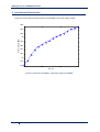
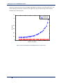
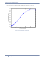
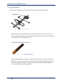
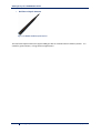
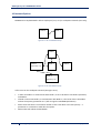
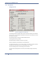
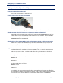
RFD900 Radio Modem Data Sheet
RFD900 Product Specifications and Performance
RFD900 Configuration
RFD900 Modem Tools User Manual
RFDesign Pty Ltd
6/97 Jijaws Street
Sumner Park, QLD 4074
rfdesign.com.au
RFDesign Pty Ltd - RFD900 Data Sheet
Contents
1.
Key Features................................................................................................................................ 4
2.
Specifications .............................................................................................................................. 5
3.
Power Levels ............................................................................................................................... 5
4.
Performance Characteristics ....................................................................................................... 6
5.
Pin Signals and Layout................................................................................................................. 9
6.
Software/GCS Support .............................................................................................................. 10
7.
Antenna Connectivity................................................................................................................ 11
7.1.
Diversity ............................................................................................................................ 11
•
Spatial Diversity..................................................................................................................... 11
•
Polarisation Diversity ............................................................................................................ 11
7.2.
Types of Antennas............................................................................................................. 12
•
Yagi Antenna ......................................................................................................................... 12
•
Quarter Wave Monopole Antenna ....................................................................................... 12
•
Half Wave Dipole Antenna .................................................................................................... 13
8.
AT Commands ........................................................................................................................... 14
9.
Air Data Rate ............................................................................................................................. 16
10.
Network Options ................................................................................................................... 17
11.
RFD900 Modem Tools User Manual ..................................................................................... 18
11.1.
Introduction .................................................................................................................. 18
11.2.
Requirements – for End Users ...................................................................................... 18
11.3.
User Interface................................................................................................................ 19
•
Configuration Tab ................................................................................................................. 19
•
Firmware Tab ........................................................................................................................ 20
12.
Frequently Asked Questions (FAQ) ....................................................................................... 21
How many antennas do I need to use? ........................................................................................ 21
How do I connect the FTDI cable to the modem? ........................................................................ 21
What do I need to upload the firmware or to change the modem configuration?...................... 21
What should I do if the RFD900 Modem Tools application keeps giving me back error messages?
...................................................................................................................................................... 21
I upgraded to V2.x firmware and the modems don't connect anymore? .................................... 21
How do I configure 2 base stations and one Airborne platform with 3 modems?....................... 21
13.
Useful Links ........................................................................................................................... 22
RFD900 Firmware.......................................................................................................................... 22
2 RFDesign Pty Ltd
31/05/2013
RFDesign Pty Ltd - RFD900 Data Sheet
RFD900 Modem Tools ................................................................................................................... 22
Software Solution Sik V1.x ............................................................................................................ 22
3DR Radio Configuration Tool ....................................................................................................... 22
3 RFDesign Pty Ltd
31/05/2013
RFDesign Pty Ltd - RFD900 Data Sheet
1. Key Features
RFD900 provides compact and yet powerful data communication. The key features are:
•
•
•
•
•
•
•
•
No configuration required for out of the box RF communications.
Operating frequency range of 902 – 928MHz
Outdoor RF line-of-site range of 40km or more depending on antennas
Air data rate speeds of up to 250kbps
Diversity antenna support
Operating temperature of -40 to +85 degrees Celsius
Dimensions of 30mm x 57mm x 12.8mm
Weight of 14.5g
Compliances and Worldwide Acceptances:
The RFD900 is designed to be compliant to AS4268:2012, and FCC 15.247. It has not been
certified as a standalone modem and should be compliance tested in the final product.
4 RFDesign Pty Ltd
31/05/2013
RFDesign Pty Ltd - RFD900 Data Sheet
2. Specifications
Performance
Supported RF Data Rates
Indoor Range
Line-Of-Sight Range
Transmit Power
Receiver Sensitivity
Low Noise Amplifiervv
4, 8, 16, 19, 24, 32, 48, 64, 96, 128, 192 and 250
500m – 1km
40km or more depending on antennas
0 to 30dBm in 1dBm steps
>121dBm at low data rates, >TBA at high data rates
>20dB
Features
Serial Data Interface
Configuration Method
Frequency Band
Interference Immunity
Serial Interface Data Rate
Antenna Options
GPIO
Compliance Standards
+3.3V nominal, 5V tolerant
AT Commands, APM Planner, Customised Configuration Tool
902MHz - 928MHz
FHSS (Frequency Hopping Spread Spectrum)
2400, 4800, 9600, 19200, 38400, 57600, 115200 baud
Yagi, ½ Wave Dipole, ¼ Wave Monopole Antenna
6 pins (Digital, ADC, PWM capable)
FCC Part 15.247, AS/NZS 4268:2008
Networking and Security
Addressing Options
Network ID: 0 –499
Channels
Up to 50 Frequency Hopping Channels
1
Supported Network Topologies
Point to point, Multipoint
1
Only available in firmware version 2.x and later
Power Requirements
Supply Voltage
Transmit Current
Receive Current
+5V nominal (+4V min, +5.5V max),
~1 A peak at max power
~60mA
3. Power Levels
Many countries have different legal power levels. Be sure to operate within the legal power
limits of the country that you are operating in. The RFD900 modem can support the power levels
between 0dBm and 30dBm in 1dBm steps. Formula (1) can be used to convert the power in dBm
into milliwatts.
= 10(
/) (1)
To calculate Effective Isotropic Radiated Power (EIRP) you can use the equation (2) below:
() = !()– #$%!%() + '!(()(2)
The FCC limit for EIRP is 4 Watts, or 36dBm for frequency hopping radios in the ISM 900 MHz
band. The Australian EIRP limit is 30dBm as defined by ACMA.
5 RFDesign Pty Ltd
31/05/2013
RFDesign Pty Ltd - RFD900 Data Sheet
4. Performance Characteristics
Figure 4.1 shows how the output power of the RFD900 varies with supply voltage.
29.6
29.4
29.2
Power Output (dBm)
29
28.8
28.6
28.4
28.2
28
27.8
27.6
4
4.5
5
5.5
Vcc (V)
Figure 4.1: Output Power of RFD900 vs. Input Supply Voltage to the RFD900
6 RFDesign Pty Ltd
31/05/2013
RFDesign Pty Ltd - RFD900 Data Sheet
Figure 4.2 shows how the current through the RFD900 varies with the transmit power level. The
current during transmission is shown by the ‘High Level’ plot and that during receive mode is
shown by the ‘Low Level’ plot.
1.4
High Level
Low Level
1.2
Current (A)
1
0.8
0.6
0.4
0.2
0
-5
0
5
10
15
Power Level (dBm)
20
25
30
Figure 4.2: Current consumption of the RFD900 modem vs. TX power level
7 RFDesign Pty Ltd
31/05/2013
RFDesign Pty Ltd - RFD900 Data Sheet
Figure 4.3 shows the occupied bandwidth (-20dB points) against the air data rate.
750
700
Occupied Bandwidth (kHz)
650
600
550
500
450
400
350
300
250
0
50
100
150
Air Data Rate (kbps)
200
250
Figure 4.3: Occupied Bandwidth vs. Air Data Rate
8 RFDesign Pty Ltd
31/05/2013
RFDesign Pty Ltd - RFD900 Data Sheet
5. Pin Signals and Layout
Pin #
1
2
3
4
5
6
7
8
9
10
11
12
13
14
15
16
Name
GND
GND
CTS
Vcc
Vusb
Vusb
RX
P2.3
TX
P2.2
RTS
P2.1
P0.1
P2.0
P2.6
GND
Direction
Either
Input
Either
Output
Either
Either
Either
Either
Either
Either
-
Description
Ground
Ground
Clear to send
Power supply
Power supply from USB
Power supply from USB
UART Data In
Digital I/O
UART Data Out
Digital I/O
Request to send
Digital I/O
Digital I/O
Digital I/O
Digital I/O
Ground
Max Voltage
0V
0V
5V
5V
5V
5V
5V
5V
5V
5V
5V
5V
5V
5V
5V
0V
Figure 5.1: Physical Pin Layout of the RFD900 Radio Modem
The FTDI cable (see Useful Links) is compatible with the RFD900 modem.
Pin 1 of the FTDI cable (black wire) should connect to pin 1 of the RFD900 header. In order to
power the modem from the +5V USB power, a jumper is needed to connect pins 4 and 6.
To power the modem from an external +5V supply, connect the power to pins 2 and 4 as
shown in figure 5.1.
In case there is need to force the modem into boot mode, short circuit pads 1 and 2 (labelled
BOOT) on the 9 way test pads.
9 RFDesign Pty Ltd
31/05/2013
RFDesign Pty Ltd - RFD900 Data Sheet
6. Software/GCS Support
The software solution (see Useful Links) is an open source development which is also compatible
with RFD900 Modem Tools (see Useful Links) and the 3DR Radio Config (see Useful Links) from
3D Robotics. It is called “SiK” and was created by Mike Smith and improved on by Andrew
Tridgell and RFDesign.
A boot loader and interface is available using RFD900 Modem Tools and field upgrade of the
modem firmware via the serial port.
The RFD900 Radio Modem is compatible with many configuration methods like the AT
Commands and APM Planner. The AT Commands can be used to change parameters such as
power levels, air data rates, serial speeds etc.
Integrated support for configuring the RFD900 Radio Modem is supported by the APM Planner,
with other GCS solutions in development. Its default serial port settings are as follows:
•
•
•
•
57600 baud rate
No parity
8 data bits
1 stop bit
The RFD900 Radio Modem has many software features which include:
•
•
•
•
•
•
•
•
Frequency Hopping Spread Spectrum
Transparent Serial Link
Configuration by simple AT commands for local radio, RT Commands for remote radio
User configurable serial data rates and air data rates
Error correction routines, Mavlink protocol framing (user selectable)
Mavlink radio status reporting (Local RSSI, Remote RSSI, Local Noise, Remote Noise)
Automatic antenna diversity switching on a packet basis in realtime
Automatic duty cycle throttling based on radio temperature in order to avoid
overheating
10 RFDesign Pty Ltd
31/05/2013
RFDesign Pty Ltd - RFD900 Data Sheet
7. Antenna Connectivity
7.1. Diversity
The RFD900 has two antenna ports and firmware which supports diversity operation of
antennas. During the receive sequence the modem will check both antennas and select the
antenna with the best receive signal. In the case of only one antenna connected, it will
automatically select the port with the antenna connected. Testing by Silicon Labs has shown
that link budgets can be improved in the order of 6-8dB by employing a diversity scheme.
•
Spatial Diversity
Spatial diversity is the case where the antennas are separated by some distance from one
another. It is recommended that two antennas connected to the RDF900 modem be separated
by at least 25cm, more if possible.
•
Polarisation Diversity
Polarisation diversity is the case where the antennas are perpendicular to each other. i.e. one
vertical, and one horizontal. This is effective in reducing multipath effects which affect one or
the other polarisation.
11 RFDesign Pty Ltd
31/05/2013
RFDesign Pty Ltd - RFD900 Data Sheet
7.2. Types of Antennas
Below are some examples of antennas that can be used with the RFD900 modems.
•
Yagi Antenna
Figure 7.1: 900MHz 6dBi Yagi Antenna
Yagi antennas are recommended for Ground-Station applications due to their size. They
have approximately 6dBi gain and give significant link budget improvement when compared
to standard dipole, or monopole antennas.
•
Quarter Wave Monopole Antenna
Figure 7.2: 900MHz Quarter Wave Monopole Antenna
Quarter Wave Monopole Antennas are recommended for air-borne, or space constrained
applications. They are required to be mounted on a ground plane of approx 20cm diameter
or more to operate as intended. Using an RF extension cable with an RPSMA bulkhead
connector will give good mounting options.
12 RFDesign Pty Ltd
31/05/2013
RFDesign Pty Ltd - RFD900 Data Sheet
•
Half Wave Dipole Antenna
Figure 7.3: 900MHz Half Wave Dipole Antenna
The half wave Dipole antenna has approx 3dBi gain with an omnidirectional radiation pattern. It is
suited for ground station, or large airborne applications.
13 RFDesign Pty Ltd
31/05/2013
RFDesign Pty Ltd - RFD900 Data Sheet
8. AT Commands
The RFD900 modem can support the Hayes ‘AT’ modem command set for configuration. The AT
command mode can be entered by using the ‘+++’ sequence. When doing this, you have to wait
for 1 second before and after entering the command mode in order to prevent data being
interpreted as data. When you are successfully in the AT command mode, an ‘OK’ prompt will be
displayed on the screen and the RFD900 modem will stop displaying information from the other
modem. Whilst in AT mode, you can use the AT commands to control the local RFD900 modem
or the RT commands to control the remote modem.
To set certain registers to a particular value, follow these steps:
1. Use the command ATSn=X where n is the register number and X is the actual value.
2. Use the command AT&W to write the new values to the RFD900 modem.
3. Use the command ATZ to reboot the RFD900 modem.
Figure 8.1 shows a table that gives a list of AT commands and their description.
AT Command
ATI
ATI2
ATI3
ATI4
ATI5
ATI6
ATI7
ATO
ATSn?
ATSn=X
ATZ
AT&W
AT&F
AT&T=RSSI
AT&T=TDM
AT&T
Description
Shows the radio version
Shows the board type
Shows board frequency
Shows board version
Shows all user settable EEPROM parameters
Displays TDM timing report
Displays RSSI signal report
Exits AT command mode
Displays radio parameter number ‘n’
Sets radio parameter number ‘n’ to ‘X’
Reboots the radio
Writes current parameters to EEPROM
Resets all parameters to factory defaults
Enables RSSI debugging report
Enables TDM debugging report
Disables debugging report
Figure 8.1: AT Commands and their description
Figure 8.2 shows a table that gives a list of RT commands and their description. The x parameter is
optional where x is the node ID. For example: use RTI,1 to get RTI value for node 1 or simply use RTI to get
the RTI value for the node set in the local NODEDESTINATION (see RFD900 Parameters in figure 8.3).
AT Command
RTI[,x]
RTI2[,x]
RTI3[,x]
RTI4[,x]
RTI5[,x]
RTI6[,x]
RTI7[,x]
Description
Shows the radio version.
Shows the board type
Shows board frequency
Shows board version
Shows all user settable EEPROM parameters
Displays TDM timing report
Displays RSSI signal report
14 RFDesign Pty Ltd
31/05/2013
RFDesign Pty Ltd - RFD900 Data Sheet
RTO[,x]
RTSn? [,x]
RTSn=X[,x]
RTZ[,x]
RT&W[,x]
RT&F[,x]
RT&T=RSSI[,x]
RT&T=TDM[,x]
RT&T[,x]
Exits AT command mode on the remote node
Displays radio parameter number ‘n’
Sets radio parameter number ‘n’ to ‘X’
Reboots the radio
Writes current parameters to EEPROM
Resets all parameters to factory defaults
Enables RSSI debugging report
Enables TDM debugging report
Disables debugging report
Figure 8.2: RT Commands and their description
Figure 8.3 shows a table with more details about the parameters that can be set in the RFD900
modem.
S Reg
#
S Register
Description
Default Val
Max Val
Min Val
0
FORMAT
This is for EEPROM version, it should
not be changed
Firmware
dependant
N/A
N/A
Should be the
same at both
ends of the link
for successful
communication
?
No
1
SERIAL_SPEED
Serial speed in ‘one byte form’
57
115
2
No
1
2
AIR_SPEED
Air data rate in one byte form
64, 128
250
2
Yes
3
NETID
Network ID. It should be the same on
both modems
25
499
0
Yes
4
TXPOWER
Transmit power in dBm. Maximum is
30dBm
20, 27
30
0
No
5
ECC
Enables or disables the golay error
correcting code
1, 0
1
1
0
Yes
6
MAVLINK
Enables or disables the MAVLink
framing and reporting
1, 0
1
1
0
No
7
OP_RESEND
OpportunicResend
1, 0
1
1
0
No
8
MIN_FREQ
Min freq in KHz
915,000
927,000
902,000
Yes
9
MAX_FREQ
Max freq in KHz
928,000
928,000
903,000
Yes
3
4
5
1
1
10
NUM_CHANNELS
Number of frequency hopping channels
50, 20
50
5
Yes
11
DUTY_CYCLE
The percentage of time to allow
transmit
100
100
10
No
12
LBT_RSSI
0
1
0
Yes
13
MANCHESTER
0
1
0
Yes
14
RTSCTS
0
1
0
No
15
NODEID
29
0
N/A
16
NODEDESTINATION
Listen before talk threshold
(This parameter shouldn’t be changed)
Manchester encoding (This parameter
shouldn’t be changed)
Ready To Send and Clear To Send (This
parameter shouldn’t be changed)
Node ID. Base node ID is 0. One node
must be acting as a base for a
multipoint environment to work.
NODECOUNT must be updated first
before updating this parameter with
bigger number.
Remote node ID to communicate with.
29
0
No
2
2
15 RFDesign Pty Ltd
2
1
65535
1
31/05/2013
RFDesign Pty Ltd - RFD900 Data Sheet
2
17
SYNCANY
18
NODECOUNT
2
Set the value to 65535 to broadcast to
all nodes. Cannot be the same as
NODEID. NODECOUNT must be
updated first before updating this
parameter with bigger number.
If set to 1, allows the modem to send
data to all non-base nodes without
finding the base. It is strongly
recommended to set the value to 0 to
avoid unwanted data communication
confusion on a multipoint
environment.
The total number of nodes.
0
1
1
0
No
3
1
30
2
Yes
Figure 8.3: RFD900 parameters
Notes:
1
Defaults for firmware version 2.* and later
2
Available only for firmware version 2.* and later
3
ECC - Software Detection and correction, extra packet information (twice the packet length) is sent to allow the recovery
of corrupted packets.
4
Injects RSSI packet when Mavlink protocol used and heartbeat packet detected.
5
Opportunicresend allows the node to resent packets if it has spare bandwith.
9. Air Data Rate
An air speed of 64kps will give a range of about 40km depending on antenna. If the air speed is
set to be lower, the range of the wireless link increases but the amount of data that you can
send will be limited. Therefore one has to compromise between range and data rate. The data
rates that you can choose are only limited to 2, 4, 8, 16, 19, 24, 32, 48, 64, 96, 128, 192 and 250.
The air data rate is chosen depending on:
•
•
•
•
•
the range that you need
the data rate that you will be sending
whether you send data in one direction or both
whether you have enabled ECC or not
whether you have APM firmware with adaptive flow control
16 RFDesign Pty Ltd
31/05/2013
RFDesign Pty Ltd - RFD900 Data Sheet
10. Network Options
RFD900 can be implemented in either simple pair (V1.x, V2.x) or multipoint network (V2.x Only).
Node 0
Node 1
Figure 10.1: Two-node Network Setup
Node 0
Node 1
(SyncAny = 0)
Node 2
Node 3
Node 4
(SyncAny = 1)
Figure 10.2: Five-node Network Setup
A few notes on the multipoint network (see Figure 10.2):
•
•
•
•
In order for Node 1 to communicate with Node 2, it has to be able to see Node 0 (the base)
and Node 2
If Node 4 cannot see Node 0, to communicate with Node 1, it has to be able to see Node 1
and set the SyncAny parameter to 1 (refer to Figure 8.3: RFD900 parameters).
Please note that there is a maximum number of one node which can have SyncAny = 1
parameter in a network to avoid data corruption.
More nodes will reduce the bandwidth.
17 RFDesign Pty Ltd
31/05/2013
RFDesign Pty Ltd - RFD900 Data Sheet
11. RFD900 Modem Tools User Manual
11.1. Introduction
This GUI is for changing RFD900 modem parameters as well as for uploading firmware.
11.2. Requirements – for End Users
Download and copy two files from RFDesign website (see Useful Links) and put them in the same
folder:
1. RFD900ModemTools.exe
2. RFD900ModemTools.glade
18 RFDesign Pty Ltd
31/05/2013
RFDesign Pty Ltd - RFD900 Data Sheet
11.3.
User Interface
•
Configuration Tab
Figure 11.1: Configuration Tab – Modem Tools
To communicate with the modem, make sure you connect the modem to the computer
using FTDI cable. Use the COM Port combobox to choose the correct COM port to which
the modem is connected.
Use the Refresh button to refresh the COM combobox list after
connecting/disconnecting a modem.
Set Node Destination to 65535 to send data to all nodes.
All other comboboxes and checkbuttons are self-explanatory.
Use Update Settings button to write setting changes to the modem. Initially, this button
is disabled and will be enabled once the Load Settings button is clicked.
Use the Load Settings button to load settings from the modem.
Use Reset Factory Settings button to reset the current modem settings to the factory
settings.
19 RFDesign Pty Ltd
31/05/2013
RFDesign Pty Ltd - RFD900 Data Sheet
•
Firmware Tab
Figure 11.2: Configuration Tab – Modem Tools
Use the COM Port combobox to choose the correct COM port to which the modem is
connected.
Use the Refresh button to refresh the COM combobox list after
connecting/disconnecting a modem.
Download the firmware from the RFDesign website (see Useful Links) and put the file on
the same folder as this RFD900 Modem Tools application. Browse for the file using the
“...” button then click the Upload button to upload the new firmware to the modem.
20 RFDesign Pty Ltd
31/05/2013
RFDesign Pty Ltd - RFD900 Data Sheet
12. Frequently Asked Questions (FAQ)
How many antennas do I need to use?
One is the minimum. Two is recommended.
How do I connect the FTDI cable to the modem?
The black cable of the FTDI (pin 1) should connect to pin 1 on the modem (see above)
What do I need to upload the firmware or to change the modem configuration?
Download the latest firmware (see Useful Links). Download the RFD900 Modem Tools (see
Useful Links). Connect the FTDI cable to the modem and to a computer. Use the RFD900
Modem Tools to upload the latest firmware or to change the modem configuration (see
RFD900 Modem Tools User Manual).
What should I do if the RFD900 Modem Tools application keeps giving me back error messages?
Make sure to connect the FTDI cable firmly into the modem. Make sure you choose the
correct COM port from the COM dropdown box and the correct Baud Rate. Try for two more
trials and if it still doesn’t work, disconnect and reconnect the modem.
I upgraded to V2.x firmware and the modems don't connect anymore?
The default setting for a modem is to have a NODEID set to 1. A network must have one
node set to 0 to be the base. The base node defines the synchronisation for the whole
network of nodes.
How do I configure 2 base stations and one Airborne platform with 3 modems?
Set the Airborne platform as follows:
NODEID = 0
NODEDESTINATION = 65535
MAVLINK = 1
Set the ground station as follows:
NODEID = 1 or 2
NODEDESTINATION = 0
MAVLINK = 1
This will allow the airborne modem to handover to multiple ground stations as it flies from
the coverage area of one ground station, to another. Both ground stations can be connected
and can control the Airborne platform simultaneously. (APM Planner using Mavlink)
21 RFDesign Pty Ltd
31/05/2013
RFDesign Pty Ltd - RFD900 Data Sheet
13. Useful Links
RFD900 Firmware
http://rfdesign.com.au/firmware/
V1.x firmware is standard SiK (open source)
V2.x firmware is multipoint SiK (MP SiK)
RFD900 Modem Tools
http://rfdesign.com.au/downloads/
FTDI Cable
http://www.ftdichip.com/Support/Documents/DataSheets/Cables/DS_TTL232R_CABLES.pdf
Software Solution Sik V1.x
https://github.com/RFDesign/SiK
3DR Radio Configuration Tool
http://vps.oborne.me/3drradioconfig.zip
22 RFDesign Pty Ltd
31/05/2013