1
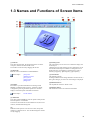
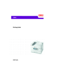
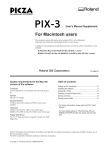
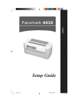
Virtual MODELA
USER'S MANUAL
Virtual MODELA is a
program that simulates
the movement of the
tool on the screen.
Contents
Contents
Part 1 Introduction
1-1 System Requirements ........................................................ 4
1-2 Overview of Virtual MODELA ........................................ 4
1-3 Names and Functions of Screen Items .............................. 5
Part 2 Operating procedure
Step 1: Get the tool path. ......................................................... 8
Step 2: Check the shape. .......................................................... 8
Step 3: Add color to the workpiece. ........................................ 9
Step 4: View the time required for cutting. ............................. 9
Step 5: Save the shape. ............................................................ 9
Part 3 Hints and Tips
3-1 Saving the shape to an image file .................................... 11
3-2 Increasing the speed of simulation .................................. 11
3-3 Make the workpiece look more realistic ......................... 12
Pasting an image on the surface of a workpiece ....... 12
Changing the strength and direction of light ............ 12
3-4 Redoing simulation for only a particular portion ............ 13
3-5 Changing the Measurement System for
Numerical Values ...................................................... 13
Part 4 Commands
4-1 Toolbar buttons ................................................................ 15
4-2 [File] menu ...................................................................... 16
[File] - [New Workpiece...] command ...................... 16
[File] - [Open...] command ....................................... 16
[File] - [Save Cutting Configuration] command ....... 17
[File] - [Export] - [BMP...] command ....................... 17
[File] - [Export] - [Clipboard] command .................. 17
[File] - [Print...] command ........................................ 17
[File] - [Print Preview] command ............................. 17
[File] - [Print Setup...] command .............................. 17
[File] - [Printing Layout] command .......................... 17
[File] - [Exit] command ............................................ 18
4-3 [Simulation] menu ........................................................... 18
[Simulation] - [Redo Cutting] command .................. 18
[Simulation] - [Start/Resume Cutting] command ..... 18
[Simulation] - [Estimate Cutting Time...]
command ...................................................... 18
[Simulation] - [Partial Zoom] command .................. 19
[Simulation] - [Original Reduced Scale]
command ...................................................... 19
[Simulation] - [Tool Setup...] command ................... 19
[Simulation] - [Workpiece Loading Position...]
command ...................................................... 19
[Simulation] - [Z-axis Smoothing] command ........... 20
[Simulation] - [Cutting-start Timing] command ....... 20
4-4 [View] menu .................................................................... 20
[View] - [Screen] - [2D Simulation] command ........ 20
[View] - [Screen] - [3D Simulation] command ........ 20
[View] - [Screen] - [3D View] command ................. 20
[View] - [Animate] command ................................... 20
[View] - [Show Grid] command ............................... 21
[View] - [Color Surface] command .......................... 21
[View] - [Set Effective Range] command ................. 21
[View] - [Texture Mapping] command ..................... 21
[View] - [256-color Palette] command ..................... 21
[View] - [Fit to Screen] command ............................ 21
[View] - [Draw While Moving] command ............... 21
[View] - [Confirmation Drawing] command ............ 21
[View] - [Toolbar] command .................................... 21
4-5 [Option] menu ................................................................. 22
[Option] - [Texture Setup...] command ..................... 22
[Option] - [Workpiece Color...] command ................ 22
[Option] - [Surface Color...] command ..................... 22
[Option] - [Light-source Setup...] command ............ 22
[Option] - [Cutting Graph] - [Cutting Volume]
command ...................................................... 23
[Option] - [Cutting Graph] - [Used Blade Length]
command ...................................................... 23
[Option] - [Cutting Graph] - [Update Interval]
command ...................................................... 23
[Option] - [Drawing Size] - [Fit to Window]
command ...................................................... 23
[Option] - [Drawing Size] - [Specify Size...]
command ...................................................... 23
4-6 [Help] menu .................................................................... 24
[Help] - [Contents] command ................................... 24
[Help] - [About...] command .................................... 24
Part 5 If You Think There's a Problem...
5-1 If You Think There’s a Problem... ................................... 26
5-2 Error Messages ................................................................ 26
Appendixies
Glossary ................................................................................. 28
Index ...................................................................................... 29
*
Windows® and Windows NT® are registered trademarks or trademarks of Microsoft® Corporation in the United States and/or
other countries.
i486 and Pentium are registered trademarks of Intel Corporation in the United States.
Copyright © 2000 Roland DG Corporation
2
Part 1
Introduction
Part 1 Introduction
1-1 System
Requirements
1-2 Overview of
Virtual MODELA
Computer
Personal computer running Windows 95, Windows 98,
Windows Me, Windows NT 4.0, or Windows 2000
Virtual MODELA is a program that accepts tool paths created
using a cutting program from Roland DG Corp. (such as
MODELA Player or 3D Engrave), and simulates the movement of the tool on the screen.
CPU
If you're using Windows 95 : i486SX or better (Pentium 100
MHz recommended)
If you're using Windows 98 : i486DX or better (Pentium 100
MHz recommended)
If you're using Windows Me : Pentium 150 MHz or better
If you're using Windows NT 4.0 : i486DX or better (Pentium 100
MHz recommended)
If you're using Windows 2000 : Pentium 133 MHz or better
Main Features of Virtual MODELA
System Memory
If you're using Windows 95 : 8 Mbyte or more (16 Mbyte or
more recommended)
If you're using Windows 98 : 16 Mbyte or more (32 Mbyte
or more recommended)
If you're using Windows Me : 32 Mbyte or more
If you're using Windows NT 4.0 : 16 Mbyte or more (32 Mbyte
or more recommended)
If you're using Windows 2000 : 32 Mbyte or more
-
-
-
-
You can display tool movement with animation.
You can view an animated display of what cutting of the
workpiece will look like. You can choose a flat view (2D
simulation) or even a three-dimensional view (3D
simulation).
You can verify the shape after cutting on the screen.
You can display a three-dimensional view of the shape
after cutting and check it on the screen.
You can rotate the view to change the perspective, as well
as zooming in and out.
You can paste images on the surface of the workpiece.
You can paste images on the surface of the workpiece, as
well as adding texture.
By pasting images of wood grain or images of metallic
colors, you can make textures like those of actual materials.
You can save on-screen images as files.
Hard Disk
5 MB or more of free space
4
Part 1 Introduction
1-3 Names and Functions of Screen Items
(9)
(8)
(7)
(1)
(2)
(3)
(6)
(4)
(5)
(1) Title bar
This shows the file name, the program name, the size of the
workpiece, and the resolution of the screen.
The window can be moved by dragging the title bar.
(2) Menu Bar
Runs the various commands for Virtual MODELA.
Related Topics
[File] menu
[Simulation] menu
[View] menu
[Option] menu
[Help] menu
(3) Toolbar
The toolbar is provided with buttons for running Virtual
MODELA commands such as [Open...] and [Save Cutting
Configuration]. Moving the mouse pointer over a button
displays a brief description of the button’s function.
Related Topics
(6) Drawing Area
This is the display area for 3D views. It limits the display area
for the object.
Changing the size of the drawing area also changes the size of
files saved with the Export command. To change the size of
the drawing area, click [Option] - [Drawing Size] - [Fit to
Window] or [Option] - [Drawing Size] - [Specify Size].
(7) Close button
This ends the program.
If changes made to the file being edited have not been saved, a
dialog box asking if you wish to save the changes is displayed.
(8) Maximize button
This expands the window to fill the screen.
(9) Minimize button
This shrinks the window to a button on the taskbar.
Toolbar buttons
(4) Status Bar
This shows Virtual MODELA’s state of operation and provides
brief descriptions of commands.
It also shows the zoom ratio for the simulation area, the cursor
location, and estimated cutting time.
(5)
When the mouse pointer is moved close to here, the pointer
changes to a diagonal arrow. You can then change the window
size by dragging.
5
Part 1 Introduction
The preceding screen is for checking the shape of a cutting
simulation (3D view). At this screen, you can rotate the object
to change the perspective, or zoom in or out.
Virtual MODELA can also display other simulation screens
beside 3D view. There are two simulation screens: a flat view
(2D simulation) and a three-dimensional view (3D simulation).
Flat view (2D simulation)
Three-dimensional view (3D simulation)
6
Part 2
Operating
procedure
Part 2 Operating Procedure
Step 1: Get the tool
path.
Step 2: Check the
shape.
Send a tool path created using MODELA Player or 3D
Engrave to Virtual MODELA.
When you do this, the cutting parameters are also sent at the
same time.
You can freely peruse the shape after the cutting simulation.
You can rotate the object to change the perspective, zoom in or
out, or move the display location.
1. Use MODELA Player or 3D Engrave to make the settings
for the cutting parameters and the process, and create the
tool path.
1. Click
to select it.
This switches to the 3D view for checking the shape.
2. Click [File] - [Output Preview].
Virtual MODELA starts and imports the tool path.
If Virtual MODELA is already running, the window does
not automatically become active. To make the Virtual
MODELA window active, click the taskbar in Windows.
3. At the same time that the tool path is received, the
simulation starts.
To only get the tool path without starting the simulation,
click [Simulation] - [Cutting-start Timing] - [Wait for
Instructions].
4. To change the animation to a three-dimensional display,
click
.
To quit animating and make processing run faster, click
to cancel the selection.
5. If you want to check the movement of the tool again, click
.
2. To rotate, click
and drag the object.
To zoom in or out, click
and drag up or down.
To change the display location, click
destination.
and drag to the
3. To display detailed information about the image, click
.
8
Part 2 Operating Procedure
Step 3: Add color
to the workpiece.
You can add color to the workpiece, making its shape easier to
see or giving it a texture like the actual material.
This example describes how to paste an image on the surface
of the workpiece. To make the setting for a single color, click
[Option] - [Workpiece Color].
1. Click
.
The [Texture Setup] dialog box appears.
2. Click [Select File].
The [Open] dialog box appears.
Step 4: View the
time required for
cutting.
You can check how much time cutting will take.
The time is an estimate calculated from the movement
distances of the respective axes. Actual cutting time may vary.
1. Click
to cancel the selection.
The display returns to the simulation screen.
3. Select the drive and folder where the image file is saved.
2. Click
.
The [Cutting Data Information] dialog box appears.
4. Click the file to select it, then click [Open].
Alternatively, double-click the file.
3. Check the expected cutting time, then click [OK].
5. The image you selected appears on the preview screen.
Check the image, then click [OK].
Step 5: Save the
shape.
6. Click
to select it.
The image is pasted to the surface of the workpiece.
After simulating cutting, save the shape to a file.
The material color and the light-source location and brightness
are saved along with the shape.
You can save the cut shapes for each process, such as up
through draft cutting or up through finishing.
1. Click [File] - [Save Cutting Configuration].
The [Save As] dialog box appears.
2. Select the destination drive and folder for saving the file.
3. Enter the file name.
4. Click [Save].
9
Part 3
Hints and Tips
Part 3 Hints & Tips
3-1 Saving the
shape to an image
file
This saves the on-screen image to a file.
Although you can also save 2D and 3D simulations to files,
this example describes how to save a 3D view to a file.
For this explanation, it is assumed that the 3D view is already
displayed, and the explanation begins at that point.
1. Click [Option] - [Drawing Size] - [Specify Size].
The [Drawing Size Setup] dialog box appears.
2. At [Drawing Size], enter the size of the image to save to a
file.
3-2 Increasing the
speed of simulation
This explains the settings that shorten the time from the start
to finish of a cutting simulation.
They select what can be omitted during simulation to optimize
the processing. The following table shows setting items and
values that are related to simulation speed.
Item
Fast
Animated view
Texture mapping
Cutting graph
Reduced scale
Z-axis smoothing
Off
Off
Off
1/100
Off
<---->
2D
<---->
Slow
3D
On
On
1/1
On
Animated view
When you don’t want to check the movement of the tool
during the simulation, you can turn off the animated view to
speed up processing.
If there is no need to view three-dimensional animation,
change the setting to 2D view.
Textures
3. Click [OK].
4. To paste a texture image to the surface of the workpiece,
click
.
To change the texture image, click
.
When you do this, the [Texture Setup] dialog box appears.
For more on how to make the settings, see the explanation
for the dialog box.
5. To change the color of the workpiece, [Option] [Workpiece Color].
The [Color] dialog box appears.
Select the color, then click [OK]. For more information,
see the explanation for the dialog box.
.
6. To change the strength or direction of the light, click
The [Light-source Setup] dialog box appears.
For more information, see the explanation for the dialog
box.
7. Rotate the object to change the perspective, zoom in or
out, or move the display location to decide on the image to
save to a file.
To rotate, click
and drag the object.
To zoom in or out, click
When animation is on, you can turn off textures to speed up
processing.
Textures are ordinarily pasted on the surfaces of completed
shapes. When texture mapping is not needed for a workpiece
that is in the process of being cut, turn it off.
Cutting graph
When you don’t want to check the cutting volume or used
blade length, you can turn off display of the graph to speed up
processing.
Reduced scale
When creating a new workpiece, you can make the setting for
the reduced scale (display scale) of the workpiece. A smaller
reduced scale results in faster processing.
The reduced scale of the workpiece is determined automatically when the tool path is imported from MODELA Player or
3D Engrave. Therefore, to choose a reduced scale before
starting simulation, make the following setting.
-
At [Simulation] - [Cutting-start Timing], make the set for
[Wait for Instructions].
-
After importing the tool path, click [File] - [New
Workpiece...] and choose a reduced scale.
-
Click
to begin simulation.
and drag up or down.
To change the display location, click
destination.
and drag to the
Z-axis smoothing
When processing for Z-axis smoothing is not needed, you can
turn it off to speed up processing.
8. Click [File] - [Export] - [BMP File].
The [Output to BMP File] dialog box appears.
9. Select the destination drive and folder for saving the file.
10. Enter the file name, then click [Save].
11
Part 3 Hints & Tips
3-3 Make the
workpiece look
more realistic
Pasting an image on the surface of a
workpiece
Changing the strength and direction of
light
You can change the strength and direction of the light striking
the workpiece to make rises and depressions easy to see and
make the workpiece appear more three-dimensional.
.
1. Click
The [Light-source Setup] dialog box appears.
You can paste an image on a workpiece, making its shape
easier to see or giving it a texture like the actual material.
For instance, you can paste a metallic-color image to make the
workpiece look like metal, or paste a wood-grain image to
make it look like wood.
1. Click
.
The [Texture Setup] dialog box appears.
2. Click [Select File].
The [Open] dialog box appears.
3. Select the drive and folder where the image file is saved.
4. Click the file to select it, then click [Open].
Alternatively, double-click the file.
5. The image you selected appears on the preview screen.
Check the image, then click [OK].
2. To change the direction of the light, change the parameters
for the light-source vector.
While using preview to check the direction of the light,
drag the X, Y, and Z sliders. You can also make changes
by typing in numeric values.
To go back to the initial values and start over, click
[Defaults].
3. To change the strength (brightness) of the light, change the
parameters for light-source brightness.
While using preview to check the strength of the light,
drag the [Primary], [Secondary], and [Threshold] sliders.
You can also make changes by typing in numeric values.
To go back to the initial values and start over, click
[Defaults].
6. Click
to select it.
The image is pasted to the surface of the workpiece.
4. Click [OK].
12
Part 3 Hints & Tips
3-4 Redoing
simulation for only
a particular portion
You can choose the area where you want to perform a cutting
simulation.
You can simulate cutting for just an area having detailed
cutting. When you do this, the reduced scale changes.
This can use less memory and result in faster processing than
enlarging the scale for the entire workpiece and displaying it
in detail.
1. If a 3D view is shown, click
simulation screen.
to switch to the 2D
2. If Set Effective Range is selected, click
selection.
3-5 Changing the
Measurement
System for
Numerical Values
The measurement system used for numerical values depends
on the unit setting for Windows in effect when Virtual
MODELA starts up. The settings for Windows can be
changed with [Measurement System] on the [Number] tab
under [Control Panel] - [Regional Setting].
If the measurement system has been changed, Virtual
MODELA must be stopped and restarted for the new setting to
take effect.
to clear the
3. Click [Simulation] - [Partial Zoom].
The area to enlarge is shown with a rectangle.
4. Align the rectangle with the area you want to enlarge, then
click. (Right-clicking cancels partial zoom.)
Cutting simulation starts.
To cancel partial zoom, click [Simulation] - [Original
Reduced Scale].
13
Part 4
Commands
Part 4 Commands
4-1 Toolbar buttons
This switches between adding and not adding color
to the surface of the workpiece.
The toolbar is provided with buttons for running Virtual
MODELA commands such as [Open...] and [Save Cutting
Configuration]. Moving the mouse pointer over a button
displays a brief description of the button’s function.
This restricts the 3D view range.
It also determines the printing area when performing
2D simulation.
The buttons provided on the toolbar are as shown below.
This pastes and image on the surface of the
workpiece.
By pasting an image of wood or metal, you can
make the workpiece look more realistic.
This creates a new, uncut workpiece.
This opens an existing cutting-configuration file.
This saves the shape of the present workpiece in a
file.
This performs the cutting simulation over again,
using the presently imported tool path.
This quits the simulation.
To resume, click
This rotates the object, changing the perspective.
This is available only during 3D view.
Click this button to activate it, then drag the object
in the direction you want to rotate it.
This zooms the view of an object in or out.
This is available only during 3D view.
Click this button to activate it, then drag the object.
Drag toward the top of the screen to zoom in or
toward the bottom to zoom out.
Shortcut:
.
This starts cutting.
If cutting was previously interrupted, it resumes
cutting.
This displays a prediction of how much time cutting
will take. The time is a general estimate.
Hold down the [Shift] key and
drag the object.
This changes an object’s displayed location on the
screen.
This is available only during 3D view.
Click this button to activate it, then drag the object
in the direction you want to move it.
Shortcut:
Hold down the [Ctrl] key and drag
the object.
This displays the simulation screen as a flat (twodimensional) view.
This enlarges or reduces what is displayed to fill the
drawing size.
This displays the simulation screen as a solid (threedimensional) view.
This displays the object using only lines. Choose this
when display speed is a priority.
This is for checking the shape after cutting simulation.
This applies color and shading to the object. This
displays a coarser image than Detail Rendering.
These change the perspective when displaying a
simulation three-dimensionally.
Clicking rotates the object by 90 degrees in the
direction of the arrow. You can control this even
while animation is in progress.
Use these when the place being cut is hidden by the
workpiece and difficult to see.
You can also change the perspective by pressing the
left and right arrow keys.
This applies color and shading to the object.
Choose this when image quality is a priority.
Conversely, the display speed is slowest.
To paste an image on the object when Texture
Mapping is on, select Precise Rendering to activate
it.
This displays the movement of the tool with
animation.
This changes the direction and brightness of incident
light, thereby changing the shading.
This selects the image to paste on the surface of the
workpiece.
15
Part 4 Commands
4-2 [File] menu
[File] - [New Workpiece...]
command
This creates a new, uncut workpiece.
Running this command opens the [Workpiece Setup] dialog
box.
Keyboard shortcut:
[Ctrl]+[N]
[Workpiece Setup] dialog box
Reduced Scale
Choose a reduced scale for the workpiece.
Reducing the scale can speed up processing for simulation
and display, but the object image becomes coarser.
Conversely, a scale that approaches 1 can make the image
more detailed, but speed is slowed.
It may be best to use this according to which factor takes
greater priority.
When the tool path is imported from MODELA Player or
3D Engrave, the reduced scale is selected automatically so
as to become a size close to the present window size.
X, Y
These show the number of points needed to display the
workpiece.
Changing the present reduced scale, the workpiece size, or
the resolution makes these values change.
Memory Use
This shows an estimate of the amount of memory Virtual
MODELA uses at the specified reduced scale, workpiece
size, and resolution.
This is the memory used only by Virtual MODELA, and
does not include the amount used by the operating system.
If the amount of memory actually installed in the computer is much less than this amount, the amount of disk
space used by virtual memory increases, and operating
speed may become slower as a result.
Workpiece
Enter the size of the workpiece.
Enter the size along the X axis in “Horizontal,” the size
along the Y axis in “Vertical,” and the size along the Z axis
in “Thickness.”
Resolution
This sets the resolution for the modeling machine (that is,
the program resolution).
Choose either 1/40 mm (0.025 mm) or 1/100 mm (0.01
mm).
Z-axis Smoothing
When reduced scale is set to 1 or 1/2, zooming in may
make small jaggedness, or steps, visible on the surface of
the workpiece. These steps are usually at a level that is not
visible unless you use something like a loupe, and are
difficult to see with the naked eye.
Also, these steps are produced by numerical calculation,
and may vary from actual cutting results due to factors
such as the rigidity of the modeling machine, the composition of the tool, and the composition of the workpiece.
When this setting is active, smoothing is performed to
reduce such small steps. To make the on-screen display
match what you see with the unaided eye, activate this
setting.
Tool Setup... button
Enter the specifications for the tool that was selected when
creating the tool path.
Simulation is carried out using this tool.
When the tool path is imported from MODELA Player or
3D Engrave, the tool specifications (blade shape, tool
diameter, and so on) are also imported at the same time.
This means there is normally no need to make these
settings.
Clicking this button displays the [Tool Setup] dialog box.
To change the tool specifications after closing the dialog
box, click [Simulation] - [Tool Setup...].
Workpiece Position... button
Enter the position of the workpiece loaded on the modeling machine.
Specify the lower-left point of the workpiece at the
number of millimeters (or the number of inches) from the
X- and Y-axis origin point.
Clicking this button displays the [Workpiece Loading
Position] dialog box.
To change the loading position after closing the dialog
box, click [Simulation] - [Workpiece Loading Position...].
[File] - [Open...] command
This opens an existing cutting-configuration file.
Running this command opens the [Open] dialog box.
Keyboard shortcut:
[Ctrl]+[O]
16
Part 4 Commands
[File] - [Save Cutting
Configuration] command
This saves the shape of the present workpiece in a file.
You can save the cut shapes for each process, such as up
through draft cutting or up through finishing.
The material color and the light-source location and brightness
are saved along with the shape.
Running this command opens the [Save As] dialog box.
Keyboard shortcut:
[File] - [Print Preview] command
This allows you to check the printing results on-screen before
actually printing the data.
Running this command makes the window change to the
Preview screen.
<Preview screen commands>
Print...
This performs printing. The [Print] dialog
box appears.
Page Setup...
This allows you to make settings for paper
size, margins, and the like. The [Page
Setup] dialog box appears.
Zoom In
This enlarges the view size of the print
image.
Zoom Out
This reduces the view size of the print
image.
Close
This closes the Preview screen for
printing.
[Ctrl]+[S]
[File] - [Export] - [BMP...] command
This saves the screen image of the scanned object as a file in
BMP format.
It saves the present perspective, workpiece color, light-source
location, and size in the file without change. Before saving the
file, make the settings for these items.
The image resolution is 72 dpi, and the number of colors is the
number set for the computer monitor.
[File] - [Print Setup...] command
[File] - [Export] - [Clipboard] command
This copies an image of the object to the clipboard.
The contents of the clipboard are retained until you copy
another image to the clipboard. To paste the contents of the
clipboard, start an image-editing program or the like and run
[PASTE].
Keyboard shortcut:
[Ctrl]+[C]
This is used to select the driver.
The [Print Setup] dialog box appears. To output data, then for
[Printer], click on the down-pointing arrow next to [Name],
then click on the driver to be used for output.
[File] - [Printing Layout] command
This allows you to set the printing position and size.
Running this command displays the [Printing Layout] dialog
box.
[File] - [Print...] command
[Printing Layout] dialog box
This outputs the image shown in the drawing area to the printer.
When you are at the 2D simulation screen, this outputs the
image in the effective range.
Running this command opens the [Print] dialog box. This
screen is normally used to make settings for paper size,
orientation, number of copies, and the like, but the available
setting items will vary according to the printer.
(1) (2)
Keyboard shortcut:
[Ctrl]+[P]
(1)
The mouse pointer changes to a diagonal double arrow
when it is placed over the black rectangle.
This can be dragged to change the size of the graphic on
paper. The graphic’s vertical and horizontal ratio is
always maintained. When the size is varied, the values
shown for [bottom] and [Right] for [Position] also change
accordingly.
This cannot be set larger than [Paper Size].
17
Part 4 Commands
(2)
The gray squares indicate the size of the graphic when
printed. The mouse pointer changes to a four-way arrow
when it is placed over one of these.
This can be dragged to change the graphic’s position on
paper when printed. When the position is varied, the
values shown for [Position] also change accordingly.
The printing position cannot be set at a location beyond
the edges of the paper.
Position
This displays, as numerical values, the graphic’s printing
position on the paper.
The values show the graphic’s distance in millimeters (or
inches) from the paper’s upper-left edge.
The printing position can also be set by typing in numerical values directly in the text box.
Related Topics
Changing the Measurement
System for Numerical Values
4-3 [Simulation] menu
[Simulation] - [Redo Cutting]
command
This performs the cutting simulation over again, using the
presently imported tool path.
Use this when you want to check the movement of the tool again.
[Simulation] - [Start/Resume
Cutting] command
This starts cutting.
If cutting was previously interrupted, it resumes cutting.
Paper Size
This displays the paper’s printing area without margins.
To change the paper size, click [Printer Setup...].
Related Topics
Changing the Measurement
System for Numerical Values
[File] - [Exit] command
This ends the program.
If changes made to the file being edited have not been saved, a
dialog box asking if you wish to save the changes is displayed.
[Simulation] - [Estimate Cutting
Time...] command
This displays a prediction of how much time cutting will take.
The time is a general estimate.
In addition to the time, you can also verify the tool movement
distance and movement range.
Running this command displays the [Cutting Data äÆformation] dialog box.
[Cutting Data Information] dialog box
Shortcut:
Click the button for closing the application window.
Estimated Cutting Time
This displays a prediction of how much time cutting will
take. The time is a general estimate.
Because the time until reaching the specified speed varies
from one modeling machine to another, the displayed time
is not necessarily accurate. Please consider it only a
general estimate.
Total Movement Distance
This shows the movement distance of the tool.
Related Topics
Changing the Measurement
System for Numerical Values
Tool Movement Range
This shows the movement range of the tool for each axis.
When the tool-path file is open, you can estimate the size
of the workpiece to prepare.
Related Topics
Changing the Measurement
System for Numerical Values
18
Part 4 Commands
[Simulation] - [Partial Zoom] command
This zooms in on a portion of the workpiece and does
simulation of the selected place over again.
Use this when you want to see only a detailed portion of the
cutting.
If you want to see the entire workpiece in detail, without
restriction to just one portion, put the reduced scale closer to
1/1. However, this requires much more memory than partial
view.
Blade Width
Enter the width of the blade for the engraving tool.
Setting range:
Related Topics
[Simulation] - [Original Reduced Scale]
command
When performing a simulation that zooms in on a portion of
the workpiece, this cancels the simulation.
0.01 to tool diameter (mm)
(0.001 to tool diameter [inch])
Changing the Measurement
System for Numerical Values
Blade Angle
Enter the angle of the blade for the engraving tool.
[Simulation] - [Tool Setup...] command
This makes the settings for the tool used in simulation.
When the tool path is imported from MODELA Player or 3D
Engrave, the tool specifications (blade shape, tool diameter,
and so on) are also imported at the same time. This means
there is normally no need to make these settings.
Running this command displays the [Tool Setup] dialog box.
Setting range:
1 to 60 degrees
If you’re using an engraving tool from Roland DG Corp.,
enter 24.2.
[Tool Setup] dialog box
[Simulation] - [Workpiece Loading
Position...] command
Tool
This selects the configuration of the tool tip.
Enter the position of the workpiece loaded on the modeling
machine.
Specify the lower-left point of the workpiece at the number of
millimeters (or the number of inches) from the X- and Y-axis
origin point.
Running this command displays the [Workpiece Loading
Position] dialog box.
[Workpiece Loading Position] dialog box
Blade Diameter (Tool Diameter)
Enter the diameter of the tool blade.
For an engraving tool, enter the diameter of the tool.
Lower Left
Specify the lower-left point of the workpiece at the
number of millimeters (or the number of inches) from the
X- and Y-axis origin point.
Related Topics
Related Topics
Changing the Measurement
System for Numerical Values
Changing the Measurement
System for Numerical Values
Reset button
This resets the position of the lower-left point to X=0,
Y=0.
19
Part 4 Commands
[Simulation] - [Z-axis Smoothing]
command
When reduced scale is set to 1 or 1/2, zooming in may make
small jaggedness, or steps, visible on the surface of the
workpiece. These steps are usually at a level that is not visible
unless you use something like a loupe, and are difficult to see
with the naked eye.
Also, these steps are produced by numerical calculation, and
may vary from actual cutting results due to factors such as the
rigidity of the modeling machine, the composition of the tool,
and the composition of the workpiece.
When this setting is active, smoothing is performed to reduce
such small steps. To make the on-screen display match what
you see with the unaided eye, activate this setting.
4-4 [View] menu
[View] - [Screen] - [2D Simulation]
command
This displays the simulation screen as a flat (two-dimensional)
view.
The status bar shows the coordinates of the point that the
pointer indicates.
To make the indicated point easier to see, cancel the effective
range setting and click the object. The pointer changes to a
cross. You can then use the keyboard arrow keys to move the
pointer.
To change to a solid (three-dimensional) view, click
press the up or down arrow key.
[Simulation] - [Cutting-start Timing]
command
or
.
To view the shape in detail after cutting simulation, click
Select the operation performed when the tool path is imported.
-
Start Cutting Immediately
This starts simulation at the same time when the tool path
is imported.
-
Cut Uncut Material Immediately
This starts simulation automatically when there is new
material that has not been cut yet.
-
Wait for Instructions
Nothing is done until you click
.
[View] - [Screen] - [3D Simulation]
command
This displays the simulation screen as a solid (three-dimensional) view.
To view from a different perspective, click
press the left or right arrow key.
or
To change to a flat (two-dimensional) view, click
the up or down arrow key.
, or
or press
To view the shape in detail after cutting simulation, click
.
[View] - [Screen] - [3D View]
command
This is for checking the shape after cutting simulation.
To rotate, click
and drag the object.
To zoom in or out, click
and drag up or down.
and drag to the
To change the display location, click
destination.
Right-drag to change the location of the light source.
[View] - [Animate] command
This displays the movement of the tool with animation.
There are two types of animation views: a flat view (2D
simulation) and a three-dimensional view (3D simulation).
To choose the flat view, click
dimensional view, click
. To choose the three-
.
20
Part 4 Commands
[View] - [Show Grid] command
[View] - [Draw While Moving] command
This toggles the display of the grid on or off.
This selects how the object is displayed on the 3D screen
during rotation, zooming in or out, or movement.
[View] - [Color Surface] command
This switches between adding and not adding color to the
surface of the workpiece.
To specify a color, click [Option] - [Surface Color].
By specifying a color other than the color of the workpiece,
you can check areas where the tool has not cut.
-
Wire Frame
This displays the object using only lines. Choose this
when display speed is a priority.
-
Quick Rendering
This applies color and shading to the object. This displays
a coarser image than Detail Rendering.
[View] - [Confirmation Drawing]
command
[View] - [Set Effective Range]
command
This restricts the 3D view range.
It also determines the printing area when performing 2D
simulation.
Restricting the range makes 3D view faster than when
displaying the entire workpiece.
[View] - [Texture Mapping]
command
This pastes and image on the surface of the workpiece.
By pasting an image of wood or metal, you can make the
workpiece look more realistic.
To select the image to paste, click [Option] - [Texture Setup].
You can paste an image only when performing detailed
rendering with 3D view.
[View] - [256-color Palette] command
When the computer monitor is set for 256 colors, use this to
display colors as attractively as possible.
-
Do Not Use
Choose this when the computer can display more than 256
colors.
-
Halftone
Choose this when you use Texture to paste an image or
pattern on the surface of the workpiece.
-
Optimize Workpiece Colors
Choose this when you specify a single color for the
workpiece color, without using Texture.
This selects how the object is displayed when on the 3D
screen when not performing any operation.
Wire Frame
This displays the object using only lines. Choose this
when display speed is a priority.
Quick Rendering
This applies color and shading to the object. This
displays a coarser image than Detail Rendering.
Detail Rendering
This applies color and shading to the object.
Choose this when image quality is a priority. Conversely, the display speed is slowest.
To paste an image on the object when Texture Mapping
is on, select Precise Rendering to activate it.
[View] - [Toolbar] command
This toggles the display of the toolbar on or off.
The toolbar is provided with buttons for running Virtual
MODELA commands such as [Open...] and [Save Cutting
Configuration]. Moving the mouse pointer over a button
displays the button’s name.
Toggling off the display of the toolbar enlarges the area of the
edit screen.
Related Topics
Toolbar buttons
[View] - [Fit to Screen] command
This enlarges or reduces what is displayed to fill the drawing
size.
To change the drawing size, click [Option] - [Drawing Size].
21
Part 4 Commands
4-5 [Option] menu
Texture Projection
This selects the direction for projecting the image onto the
object.
Depending on the shape of the curved surfaces, choose the
orientation that produces the most natural appearance.
[Option] - [Texture Setup...]
command
This selects the image to paste on the surface of the
workpiece.
to
To paste a selected image on the workpiece, click
activate it.
You can paste an image only when performing detailed
rendering with 3D view.
Running this command displays the [Texture Setup] dialog
box.
[Texture Setup] dialog box
(2)
[Option] - [Workpiece Color...]
command
This specifies the color of the workpiece.
Running this command displays the [Color] dialog box.
[Option] - [Surface Color...] command
(1)
This specifies the block surface color for uncut material.
To color the surfaces of the workpiece, select [View] - [Add
Color] to activate it.
Running this command displays the [Color] dialog box.
[Option] - [Light-source Setup...]
command
This changes the direction and brightness of incident light,
thereby changing the shading.
Running this command displays the [Light-source Setup]
dialog box.
[Light-source Setup] dialog box
Select File
This selects the image to paste on the surface of the
workpiece.
Clicking it displays the [Open] dialog box.
The image to be specified must be a file in bitmap (BMP)
format.
(1)
This selects a pattern to paste on the surface of the
workpiece from among patterns (image files) that you
have specified previously.
Click the drop-down arrow to display the list of image
files. Click the image file you want.
To choose the file you want, click [Select File].
(2)
This displays the image file you selected.
Fit to Workpiece Size
This resizes the image to fit the size of the object displayed with 3D view.
(1)
Primary Light-source Vector - X, Y, Z
Virtual MODELA offers two light sources: primary and
secondary.
This sets the direction of the primary light source,
changing the orientation of the light striking the object.
You cannot change the direction of the secondary light
source.
Specify the direction of the light source by specifying its
coordinates in an imaginary cube whose length on a side is
2.
Texture Image Orientation
This changes the orientation of the image.
You can rotate it in steps of 90 degrees.
To mirror the image (reversing it from left to right), click
[Mirror].
22
Part 4 Commands
Defaults - Primary Light-source Vector
This returns the direction of the primary light source to its
default value.
The default is X=-0.5, Y=0.5, Z=1.
Light-source Brightness - Primary
This adjusts the brightness of the primary light source.
The primary light source is at infinite distance in the
direction specified by the primary light-source vector.
Larger values make it brighter, and smaller values make it
dimmer.
Setting range:
0 to 1000
Light-source Brightness - Secondary
This adjusts the brightness of the secondary light source.
The secondary light source is at infinite distance on the Z
axis. You cannot change the direction of the light.
Larger values make it brighter, and smaller values make it
dimmer.
Setting range:
0 to 1000
Light-source Brightness - Threshold
This changes the luster of the object.
Larger values make it less glossy, and smaller values make
it glossier.
Setting range:
100 to 900
Default - Light-source Brightness
This returns the brightness of the light source to its default
value.
The default is Primary=950, Secondary=50, Threshold=750.
[Option] - [Cutting Graph] - [Update
Interval] command
This selects the update interval for the graphs of cutting
volume and used blade length.
[Option] - [Drawing Size] - [Fit to
Window] command
This resizes the drawing area during 3D view to the same as
the window size.
Changing the size of the drawing area also changes the size of
files saved with the Export command. To specify the size you
want for the drawing area, click [Option] - [Drawing Size] [Specify Size].
[Option] - [Drawing Size] - [Specify
Size...] command
This sets the size of the drawing area during 3D view to the
size you want.
Changing the size of the drawing area also changes the size of
files saved with the Export command.
Running this command displays the [Drawing Size Setup]
dialog box.
[Drawing Size Setup] dialog box
(1)
Changing the primary light source vector and the lightsource brightness alters the displayed image.
This lets you check the general results before you confirm
the settings.
[Option] - [Cutting Graph] - [Cutting
Volume] command
This displays a bar graph showing the volume of material cut
by the tool per second.
The graph’s horizontal axis is time, and the vertical axis is
volume.
To change the range of the vertical axis, click the spin box in
the upper-right area of the graph. To change the range of the
horizontal axis, click [Option] - [Cutting Graph] - [Update
Interval] and choose one of the selections.
Drawing Size
Enter the drawing size.
The units are in pixels.
[Option] - [Cutting Graph] - [Used Blade
Length] command
This displays a bar graph showing the length of the tool
cutting into the workpiece.
The graph’s horizontal axis is time, and the vertical axis is
length.
To change the range of the vertical axis, click the spin box in
the upper-right area of the graph. To change the range of the
horizontal axis, click [Option] - [Cutting Graph] - [Update
Interval] and choose one of the selections.
23
Part 4 Commands
4-6 [Help] menu
[Help] - [Contents] command
This displays the contents page for online help.
[Help] - [About...] command
This displays the version number and copyright information
for Virtual MODELA.
24
Part 5
If You Think
There's a
Problem...
Part 5 If You Think There's a Problem...
5-1 If You Think
There’s a
Problem...
5-2 Error Messages
-
Insufficient memory. Continue?
Virtual MODELA is using more memory than is installed
in the computer.
Continuing processing without change results in more
frequent use of virtual memory on the hard disk, which
may cause processing to take more time.
To reduce the amount of memory that Virtual MODELA
uses, make the scale of the workpiece smaller.
-
Could not perform 3D display.
The amount of memory required for 3D view was not
available.
To reduce the amount of memory that 3D view consumes,
make the drawing size smaller.
Virtual MODELA doesn’t function.
-
-
Does the computer you’re using provide the correct
operating environment for Virtual MODELA?
Check the conditions for the Virtual MODELA operating
environment and make sure that the computer offers a
suitable environment.
Was the software installed using the setup program?
The setup program puts the files for Virtual MODELA in
the necessary locations to enable the software to be used
under Windows.
Printing doesn’t work.
-
Was the correct port selected for the printer driver?
The data-output port is set with the printer driver.
Open the driver’s properties, and on the [Details] tab,
check the setting for [Print to the following port:].
-
Is the cable connected?
Switch off the power to the computer and the printer, and
use an interface cable to connect the two devices.
-
Is the correct type of cable used?
The type of interface cable may vary according to the
computer model. Make the connection with the correct
type of cable for the computer.
Be sure the computer and the printer are both switched off
before attempting to attach or disconnect the interface
cable.
26
-Appendixies
Appendixies
Glossary
BMP
Bitmap data is a data format that represents images (text and
shapes) as a collection of dots. Most paint-type software
applications show images as bitmaps.
Resolution
This is a scale that indicates the precision of images displayed
on screen, printed on the printer, or acquired with the scanner.
The larger the number, the more detailed and attractive is the
image it represents.
Clipboard
The clipboard is used to hold data temporarily when it is being
copied or cut. The clipboard is a standard feature of Windows.
28
Appendixies
Index
Start/Resume Cutting ............................................. 18
Surface Color... ...................................................... 22
Texture Mapping .................................................... 21
Texture Setup... ...................................................... 22
Tool Setup... ........................................................... 19
Toolbar ................................................................... 21
Update Interval ...................................................... 23
Used Blade Length ................................................ 23
Workpiece Color... ................................................. 22
Workpiece Loading Position... ............................... 19
Z-axis Smoothing ................................................... 20
[Confirmation Drawing] command ................................ 21
[Contents] command ...................................................... 24
Cutting Graph ................................................................. 23
Cutting graph ................................................................. 11
[Cutting Volume] command ........................................... 23
[Cutting-start Timing] command ................................... 20
Symbols
[256-color Palette] command ......................................... 21
2D simulation .............................................................. 4, 6
[2D Simulation] command ............................................. 20
3D simulation .............................................................. 4, 6
[3D Simulation] command ............................................. 20
[3D View] command ...................................................... 20
A
[About...] command ....................................................... 24
Add color ......................................................................... 9
Amount of memory ........................................................ 26
[Animate] command ...................................................... 20
Animation ............................................................ 4, 8, 11
B
BMP format .................................................................... 17
[BMP...] command ......................................................... 17
Button ............................................................................. 15
D
Detail Rendering ............................................................ 21
Dialog box
Drawing Size Setup ............................................... 23
Light-source Setup ................................................. 22
Printing Layout ...................................................... 17
Texture Setup ......................................................... 22
Tool Setup .............................................................. 19
Workpiece Loading Position .................................. 19
Workpiece Setup .................................................... 16
Direction of light ............................................................ 12
Display scale .................................................................. 11
Displayed location ......................................................... 15
[Draw While Moving] command ................................... 21
Drawing Area ................................................................... 5
Drawing Size .................................................................. 23
[Drawing Size Setup] dialog box ................................... 23
C
Clipboard ................................................................. 17, 28
[Clipboard] command .................................................... 17
Close button ..................................................................... 5
[Color Surface] command .............................................. 21
Command
256-color Palette .................................................... 21
2D Simulation ........................................................ 20
3D Simulation ........................................................ 20
3D View ................................................................. 20
About... .................................................................. 24
Animate .................................................................. 20
BMP... .................................................................... 17
Clipboard ............................................................... 17
Color Surface ......................................................... 21
Confirmation Drawing ........................................... 21
Contents ................................................................. 24
Cutting Volume ...................................................... 23
Cutting-start Timing ............................................... 20
Draw While Moving .............................................. 21
Estimate Cutting Time... ........................................ 18
Exit ......................................................................... 18
Fit to Screen ........................................................... 21
Fit to Window ........................................................ 23
Light-source Setup... .............................................. 22
New Workpiece... ................................................... 16
Open... .................................................................... 16
Original Reduced Scale ......................................... 19
Partial Zoom .......................................................... 19
Print Preview ......................................................... 17
Print Setup... .......................................................... 17
Print... ..................................................................... 17
Printing Layout ...................................................... 17
Redo Cutting .......................................................... 18
Save Cutting Configuration ................................... 17
Set Effective Range ............................................... 21
Show Grid .............................................................. 21
Specify Size... ........................................................ 23
E
Effective Range .............................................................. 13
Error Messages ............................................................... 26
[Estimate Cutting Time...] command ............................. 18
[Exit] command ............................................................. 18
Expected cutting time ...................................................... 9
Export ............................................................... 11, 17, 23
[Export] .......................................................................... 17
F
[File] menu ..................................................................... 16
[Fit to Screen] command ................................................ 21
[Fit to Window] command ............................................. 23
Flat view ............................................................. 6, 15, 20
H
[Help] menu ................................................................... 24
L
Light-source brightness .................................................. 12
29
Appendixies
Status Bar ......................................................................... 5
Strength of light ............................................................. 12
[Surface Color...] command ........................................... 22
Light-source location and brightness ............................... 9
[Light-source Setup] dialog box .................................... 22
[Light-source Setup...] command ................................... 22
Light-source vector ........................................................ 12
T
M
Taskbar ............................................................................. 8
Texture ...................................................................... 9, 11
Texture image ................................................................. 11
Texture mapping ............................................................ 11
[Texture Mapping] command ......................................... 21
Texture Setup ................................................................. 11
[Texture Setup] dialog box ............................................. 22
[Texture Setup...] command ........................................... 22
Three-dimensional .................................................. 15, 20
Three-dimensional view ................................................... 6
Threshold ....................................................................... 23
Time ................................................................................. 9
Tool Movement Range ................................................... 18
Tool path ................................................................... 8, 16
[Tool Setup] dialog box .................................................. 19
[Tool Setup...] command ................................................ 19
Toolbar .......................................... 5, 15, 16, 18, 20, 21
[Toolbar] command ........................................................ 21
Total Movement Distance .............................................. 18
Two-dimensional ..................................................... 15, 20
Material Color ................................................................ 11
Maximize button .............................................................. 5
Measurement .................................................................. 13
Menu
File ......................................................................... 16
Help ........................................................................ 24
Option .................................................................... 22
Simulation .............................................................. 18
View ....................................................................... 20
Minimize button ............................................................... 5
N
Names and Functions of Screen Items ............................. 5
[New Workpiece...] command ....................................... 16
O
[Open...] command ........................................................ 16
[Option] menu ................................................................ 22
[Original Reduced Scale] command .............................. 19
Overview .......................................................................... 4
U
[Update Interval] command ........................................... 23
[Used Blade Length] command ..................................... 23
P
[Partial Zoom] command ............................................... 19
Perspective ..................................................................... 15
Preview screen ............................................................... 12
Primary Light-source Vector .......................................... 22
Print ................................................................................ 17
[Print Preview] command .............................................. 17
[Print Setup...] command ............................................... 17
[Print...] command ......................................................... 17
[Printing Layout] command ........................................... 17
[Printing Layout] dialog box .......................................... 17
Printing position ............................................................. 17
V
[View] menu ................................................................... 20
Virtual memory .............................................................. 16
W
Wire Frame ..................................................................... 21
[Workpiece Color...] command ...................................... 22
[Workpiece Loading Position] dialog box ..................... 19
[Workpiece Loading Position...] command ................... 19
[Workpiece Setup] dialog box ........................................ 16
Q
Quick Rendering ............................................................ 21
R
[Redo Cutting] command ............................................... 18
Redoing .......................................................................... 13
Reduced scale .......................................................... 11, 20
Resolution ............................................................... 17, 28
Rotate ............................................................... 11, 15, 20
Z
Z-axis Smoothing ........................................................... 20
Z-axis smoothing ........................................................... 11
[Z-axis Smoothing] command ....................................... 20
Zoom In .......................................................................... 17
Zoom in/out ...................................................... 11, 15, 20
Zoom Out ....................................................................... 17
S
Save ......................................................................... 15, 17
[Save Cutting Configuration] command ........................ 17
Save the shape .................................................................. 9
Saving the shape to an image file .................................. 11
Scale ............................................................................... 16
Secondary light source ................................................... 23
[Set Effective Range] command .................................... 21
[Show Grid] command ................................................... 21
[Simulation] menu ......................................................... 18
Simulation speed ............................................................ 11
Solid view ............................................................... 15, 20
[Specify Size...] command ............................................. 23
[Start/Resume Cutting] command .................................. 18
30
R2-000922