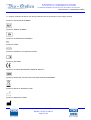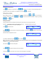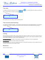
1
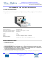
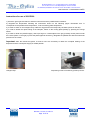
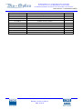
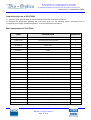
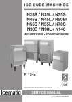
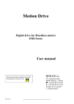
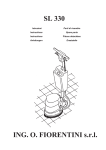
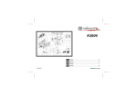
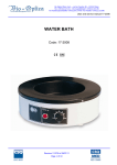
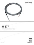
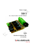
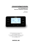
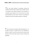
Bio Optica Milano S.p.A. • via San Faustino 58 • I-20134 Milano
Tel. +39 02.21.27.13.1 • Fax Acquisti/Export +39 02.21.54.155
Fax Assistenza/Contabilità +39 02.26.41.74.48 • Fax Vendite +39 02.21.53.000
User manual – CentralinaCD1000/L
EMBEDDING STATION CD1000/L
Code: 23-CD1000/L
In the photo, from the left: Freezer Plate, Paraffin Dispenser, Thermal Unit.
Revision 110714 of 14/07/11
Page 1 of 20
Bio Optica Milano S.p.A. • via San Faustino 58 • I-20134 Milano
Tel. +39 02.21.27.13.1 • Fax Acquisti/Export +39 02.21.54.155
Fax Assistenza/Contabilità +39 02.26.41.74.48 • Fax Vendite +39 02.21.53.000
User manual – CentralinaCD1000/L
USE PRECAUTIONS
Before using the instrument, read carefully the instructions and warnings contained in
this manual and keep it for further reference. They supply important indications regarding
the functions and safety for installing, using and maintaining the instrument.
Bio-Optica Milano S.p.A. cannot be held responsible for any damage caused by improper
or incorrect use and by the non-observance of any of the prescription provided in this
manual and by the safety regulations in force.
1. After unpacking, make sure that the instrument is complete and not damaged by transport.
2. Before connecting the instrument to the power supply make sure that its rating corresponds to that of the power
supply.
3. This instrument must only be used for the purpose for which it was designed, that is, as embedding station for
laboratory use. Any other use is to be considered improper and therefore hazardous.
4. The instrument must only be used by authorized and professionally qualified technician.
5. The electrical safety of this instrument can be guaranteed only if it is correctly connected to an efficient earth
circuit as indicated by current electrical safety regulations. It is necessary to check this fundamental safety
prerequisite, and if in doubt, ask to check the circuit. The instrument is provided with a power supply cable having 2
wires + ground tap that have to be connected to the power supply socket.
6. Do not remove the chassis or parts of it during operation. Switch off the instrument and disconnect the power
supply cable before opening it. This operation must to be effected only by authorized and professionally qualified
technician.
7. To eliminate instrument malfunctioning risks, do not work near strong magnetic fields and do not use transmitters
such as cellular phones near the instrument. In case of serious malfunctioning switch off the instrument and contact
the Technical Assistance Service.
8. All waste material, both infectious and radioactive, deriving from the appliance working cycle must be disposed in
compliance with the regulation in force.
This appliance is marked from this symbol, in compliance with EU directive 2002/96/CE regarding
electric and electronic appliances waste. This mean that the instrument, at the end of its useful life, must be collected
separately from other refuse. The user must deliver it to the special differentiated refuse collection centres, that are
predisposed by the public authority.
9. The contents of this manual is subject to change without further notice.
10. Please find enclosed the declaration of conformity.
Revision 110714 of 14/07/11
Page 2 of 20
Bio Optica Milano S.p.A. • via San Faustino 58 • I-20134 Milano
Tel. +39 02.21.27.13.1 • Fax Acquisti/Export +39 02.21.54.155
Fax Assistenza/Contabilità +39 02.26.41.74.48 • Fax Vendite +39 02.21.53.000
User manual – CentralinaCD1000/L
11. Graphic symbols indicated on the label (positioned near the instrument’s power supply socket):
Symbol for CATALOGUE NUMBER:
Symbol for SERIAL NUMBER:
Symbol for ALTERNATING CURRENT:
Symbol for FUSE:
Symbol for CONSULT THE INSTRUCTIONS:
Symbol for EC MARK:
Symbol for IN VITRO DIAGNOSTIC-MEDICAL DEVICE:
Symbol for DISPOSAL OF ELECTRIC AND ELECTRONIC EQUIPMENT:
Symbol for DATE OF MANUFACTURE:
Symbol for MANUFACTURER:
Revision 110714 of 14/07/11
Page 3 of 20
Bio Optica Milano S.p.A. • via San Faustino 58 • I-20134 Milano
Tel. +39 02.21.27.13.1 • Fax Acquisti/Export +39 02.21.54.155
Fax Assistenza/Contabilità +39 02.26.41.74.48 • Fax Vendite +39 02.21.53.000
User manual – CentralinaCD1000/L
DESCRIPTION
Modular instrument used to effect the paraffin inclusion of cytological and histological samples.
Composed of three separate modules called Paraffin Dispenser, Thermal Unit and Freezer Plate which can be
positioned in a different way depending on the operator’s requirements.
Dimensional features
Dimensions (WxDxH):
1200x560x290 mm.
Weight:
68 Kg.
Electrical connections
Power supply:
230V~ 50/60Hz.
Power:
1630 Watt (in total).
Other connections
Water connections:
Not necessary.
Fumes aspiration/filtration:
Not necessary.
Technical features common to the three modules
Working temperature adjustment:
Through electronic thermostat with microprocessor.
Working parameters visualization
and modification:
Through control panel with digital display, bilingual (Italian and English).
Programming possibility:
Instrument starting and switching off, weekly.
Installation
Position the instrument on a level and stable working bench and connect it to the power supply socket (230V~
50/60Hz) using the provided cable.
For the Freezer Plate: Make sure that the back grid has at least a 10 cm free space in order to allow the aeration of
the cooling system.
Important: Do not use any extension or adapter and do not modify the provided cable.
Revision 110714 of 14/07/11
Page 4 of 20
Bio Optica Milano S.p.A. • via San Faustino 58 • I-20134 Milano
Tel. +39 02.21.27.13.1 • Fax Acquisti/Export +39 02.21.54.155
Fax Assistenza/Contabilità +39 02.26.41.74.48 • Fax Vendite +39 02.21.53.000
User manual – CentralinaCD1000/L
Backlit control panel
The working of the control panel is equal for all the three modules. The only difference regards T1 and T2 probes:
- In the Freezer Plate there is only T1 probe, which measures the temperature of the stainless steel plate.
- In the Paraffin Dispenser T1 probe measures the temperature of the paraffin basin, T2 probe the temperature of the
working plate.
- In the Thermal Unit T1 probe measures the temperature of the upper chamber, T2 probe the temperature of the
lower basin.
TIMER DELAY: Delay the automatic instrument’s turn off.
TEMPERATURE SETTING: Set the desired temperature value.
MENU: Allows to access the functions.
ENTER: Accept/store values.
UP/DOWN SELECTIONS BUTTONS: Modify values or select the functions.
Display
Time
Automatic switching off
(Timer)
Day
MON
T1
08:35
56°
18:30
T2 58°
Temperature measured
from T1 probe
Temperature measured
from T2 probe
Revision 110714 of 14/07/11
Page 5 of 20
Bio Optica Milano S.p.A. • via San Faustino 58 • I-20134 Milano
Tel. +39 02.21.27.13.1 • Fax Acquisti/Export +39 02.21.54.155
Fax Assistenza/Contabilità +39 02.26.41.74.48 • Fax Vendite +39 02.21.53.000
User manual – CentralinaCD1000/L
Setting the temperature
Press
to display the temperature and
to change it. The value is saved automatically (after 5
for 4 seconds.
seconds the main screen appears on the display) or by pressing
Setting time and date
Before setting the timer, control time and date by pressing simultaneously
necessary, modify it by pressing
. Press
. Press
and
. The day will flash; if
to view the time and, if necessary, modify it by pressing
to exit.
Setting the timer
The timer allows to plan the starting and switching off of the instrument for every day of the week.
Example: From Monday to Friday: starting (ON) at 08.00 a.m. - switching off (OFF) at 18.30 p.m.
On Saturday and on Sunday: switching off.
Press
Progr
Monday
to view this screen:
Press
to set the starting or switching off for Monday. To confirm press
week, up to Sunday.
Afterwards will be displayed this screen:
Progr
Start
To modify the starting time, press
and, to confirm,
Day
TIMER
Work
. Repeat for every day of the
Timer
T1.
08.00
.
[Where provided, a second screen will appear and it will be possible to set the starting time of the second
resistance “T2”. Use the same procedure].
After pressing
Press
At last press
Progr
STOP
, this screen will appear:
to modify the switching off of the resistance.
for 3 seconds to exit. The main screen will appear on the display.
Revision 110714 of 14/07/11
Page 6 of 20
Timer
18.30
Bio Optica Milano S.p.A. • via San Faustino 58 • I-20134 Milano
Tel. +39 02.21.27.13.1 • Fax Acquisti/Export +39 02.21.54.155
Fax Assistenza/Contabilità +39 02.26.41.74.48 • Fax Vendite +39 02.21.53.000
User manual – CentralinaCD1000/L
Timer delay
To delay the automatic switching off of the instrument, press
flash, it will be possible to modify it by pressing
MON
T1
08:35
56°
for 4 seconds. When the switching off time will
.
18:30
This operation does not modify the preset switching off time.
Timer esclusion (manual operating)
To operate the instrument manually, it is necessary to set all days to ON. (see “Setting the timer”). On the display
will appear ON. To start or switching off the instrument it will be necessary to use the general switch every time.
MON
T1
08:35
56°
ON
Cleaning
Before effecting the cleaning, switch off the instrument and unplug the cable from the socket. Use only alcohol or
non-aggressive detergents. Do not use abrasive products or acids in order to avoid ruining the varnished or plastic
parts. A plastic spatula can be used to remove residual paraffin.
For Paraffin Dispenser: the paraffin collecting drawer, placed on the frontal side, must to be emptied daily.
For Freezer Plate: effect the periodic cleaning of the back grids.
The instrument does not need to be sterilized because is not expected the treatment of fresh samples but only of
histological samples fixed and included in paraffin.
Maintenance
Effect the periodic cleaning.
Revision 110714 of 14/07/11
Page 7 of 20
Bio Optica Milano S.p.A. • via San Faustino 58 • I-20134 Milano
Tel. +39 02.21.27.13.1 • Fax Acquisti/Export +39 02.21.54.155
Fax Assistenza/Contabilità +39 02.26.41.74.48 • Fax Vendite +39 02.21.53.000
User manual – CentralinaCD1000/L
Replacing the fuses
If the instrument doesn’t start, check that the electric cable has been connected properly, there is current and the two
fuses under the instrument’s socket aren’t burnt. If necessary, change them with fuses of identic value.
Fuses holder socket (N. 2 delayed fuses).
Instructions for the replacement: Switch off the appliance and unplug the cable from the socket. Make a light
pressure on the little carter covering the fuses (if necessary using a little screwdriver), change them, close the carter
and check the instrument’s ignition.
Revision 110714 of 14/07/11
Page 8 of 20
Bio Optica Milano S.p.A. • via San Faustino 58 • I-20134 Milano
Tel. +39 02.21.27.13.1 • Fax Acquisti/Export +39 02.21.54.155
Fax Assistenza/Contabilità +39 02.26.41.74.48 • Fax Vendite +39 02.21.53.000
User manual – CentralinaCD1000/L
FEATURES OF THE SEPARATE MODULES
1) Paraffin Dispenser 23-DP500
Paraffin dispenser used to effect the inclusion of histological samples quickly and cleanly. The constant temperature
of the paraffin basin, of the working plate and the separate heating of the dispensing nozzle assure the optimal
working temperature.
Dimensions (WxDxH):
360x550x290 mm.
Paraffin basin dimensions (WxDxH):
300x150x100 mm. Capacity ca. 4 litres.
Working plate dimensions (WxD):
360x300 mm.
Weight:
21 kg.
Power:
700 Watt.
Fuses:
N. 2 fuses of 4 Ampere - 5x20 mm - T4AH250V.
Working temperature:
Adjustable from +20°C to +70°C. Reading precision ±2°C.
Structural features of 23-DP500
Painted sheet steel chassis.
Structure consisting of two working areas heated and thermostated separately:
Stainless steel paraffin basin with cover, used to melt scale paraffin.
Aluminium working plate provided with 6 heated seats for tweezers and paraffin collecting drawer, both heated.
Paraffin dispensing system through dispensing nozzle controlled by proximity sensor (free of maintenance) or
through pedal (optional accessory). Flow adjustment through regulation knob.
Lighting through articulated halogen lamp of 12 Volt - 5 Watt.
Cold point for rapid cooling: ∅ 55 mm spot cooled at ca. -3°C through “Peltier” pl ate, with independent ignition.
Revision 110714 of 14/07/11
Page 9 of 20
Bio Optica Milano S.p.A. • via San Faustino 58 • I-20134 Milano
Tel. +39 02.21.27.13.1 • Fax Acquisti/Export +39 02.21.54.155
Fax Assistenza/Contabilità +39 02.26.41.74.48 • Fax Vendite +39 02.21.53.000
User manual – CentralinaCD1000/L
Instructions for use of 23-DP500
1) Press the green general switch to start the instrument and the paraffin basin resistance.
2) Regulate the temperature following the instructions shown on the following pages. Remember that T1
corresponds to the paraffin basin temperature, T2 to the working plate temperature.
3) In order to switch on the halogen lamp, rotate the ring placed on the lamp body clockwise (Photo on the left).
4) In order to obtain the rapid cooling of the samples, switch on the cooling plate (Peltier) by pressing the orange
switch.
5) In order to obtain the paraffin supply, draw up a finger or a metal object to the grey proximity sensor placed under
the nozzle (Photo on the right) or press the pedal (optional accessory). Regulate the paraffin flow with the white knob
placed over the nozzle.
Important: After the instrument ignition, at least 2 hours are necessary to obtain the complete heating of the
dispenser and the consequent supply of melted paraffin.
Halogen lamp.
Dispensing nozzle controlled by proximity sensor.
Revision 110714 of 14/07/11
Page 10 of 20
Bio Optica Milano S.p.A. • via San Faustino 58 • I-20134 Milano
Tel. +39 02.21.27.13.1 • Fax Acquisti/Export +39 02.21.54.155
Fax Assistenza/Contabilità +39 02.26.41.74.48 • Fax Vendite +39 02.21.53.000
User manual – CentralinaCD1000/L
Main components of 23-DP500
CODE
DESCRIPTION
QUANTITY
37-AR09E2F6A
6 ampere wire filter
1
37-B311/2N
N. 2 temperatures thermal timer
1
37-BSP/1
tube for block
3
37-BSP50X46
paraffin waste block
1
37-FI100
paraffin tank filter
1
37-FP604
noise filter
1
37-GH100
paraffin tank metal ring
1
37-RS208
static relay
1
37-0041
panel socket
1
37-129C240
electric valve body
1
37-129-432
green waterproof switch
1
37-181-D
diode
1
37-223-8601N
transformer
1
37-1003
resistance
1
37-1023
rubber feets
4
37-1044
paraffin passage block
1
37-1044/1
brass nut for block
1
37-1044/2
brass nipple
1
37-1044/3
basin fixing joint
1
37-1045
power supply cable
1
37-1046
peltier cell
1
37-1046A
peltier cell feeder
1
37-1047/1
aluminium plate
1
37-1047/2
plexiglas plate
1
37-1047/3
aluminium disc for peltier
1
37-1050
paraffin dispenser block
1
37-1050/1
stainless steel rubber holder
1
37-1050/2
delrin screw
1
37-1050/3
stainless steel nozzle
1
37-1050/4
teflon guide
1
37-4039
1
37-4043N
heat dissipator
halogen lamp
(spare bulb code: 37-370-3077)
polycarbonate panel
37-4050F
female connector
1
37-4225
dispenser sensor
1
37-6012
mica resistance
1
37-6013
waste drawer resistance
1
37-6014
cartridge resistance
2
37-4041
1
1
37-7001
fan
1
37-24548B2BY
bipolar switch
1
Revision 110714 of 14/07/11
Page 11 of 20
Bio Optica Milano S.p.A. • via San Faustino 58 • I-20134 Milano
Tel. +39 02.21.27.13.1 • Fax Acquisti/Export +39 02.21.54.155
Fax Assistenza/Contabilità +39 02.26.41.74.48 • Fax Vendite +39 02.21.53.000
User manual – CentralinaCD1000/L
37-1098/1
upper chassis
1
37-1098/2
hinged cover
1
37-1098/3
lower base
1
37-1098/4
paraffin basin
1
37-1098/5
paraffin recovery drawer
1
37-1098/6
paraffin drawer base
1
37-1098/7
drawer frontal
1
37-1098/8
internal basin
1
37-1098/9
resistance plate
1
37-1098/10
mask for display
1
MU23-DP500
user manual
1
Revision 110714 of 14/07/11
Page 12 of 20
Bio Optica Milano S.p.A. • via San Faustino 58 • I-20134 Milano
Tel. +39 02.21.27.13.1 • Fax Acquisti/Export +39 02.21.54.155
Fax Assistenza/Contabilità +39 02.26.41.74.48 • Fax Vendite +39 02.21.53.000
User manual – CentralinaCD1000/L
Electric wiring diagram 23-DP500
Revision 110714 of 14/07/11
Page 13 of 20
Bio Optica Milano S.p.A. • via San Faustino 58 • I-20134 Milano
Tel. +39 02.21.27.13.1 • Fax Acquisti/Export +39 02.21.54.155
Fax Assistenza/Contabilità +39 02.26.41.74.48 • Fax Vendite +39 02.21.53.000
User manual – CentralinaCD1000/L
2) Thermal Unit 23-UT200L
Thermal unit used for paraffin and blocks heating.
Dimensions (WxDxH):
360x550x290 mm.
Blocks upper chamber dimensions (WxDxH):
315x210x104 mm.
Removable upper basin (WxDxH):
310x195x100 mm. Capacity ca. 5,5 litres.
Samples lower basin dimensions (WxDxH):
265x205x40 mm. Capacity ca. 3 litres.
Weight:
17 kg.
Power:
330 Watt.
Fuses:
N. 2 fuses of 3,15 Ampere - 5x20 mm - T3.15AH250V.
Working temperature:
Adjustable from +20°C to +70°C. Reading precision ±2°C.
Structural features of 23-UT200L
Painted sheet steel chassis.
Structure consisting of two stainless steel working areas heated and thermostated separately:
Fixed upper chamber with cover used for the inclusion blocks preheating.
Removable upper basin that can be used to contain the cassette holder baskets coming directly from the
processor with maximum height of 100 mm.
Removable lower basin with horizontal sliding cover, used to melt scale paraffin where processed samples are
placed before being included.
Revision 110714 of 14/07/11
Page 14 of 20
Bio Optica Milano S.p.A. • via San Faustino 58 • I-20134 Milano
Tel. +39 02.21.27.13.1 • Fax Acquisti/Export +39 02.21.54.155
Fax Assistenza/Contabilità +39 02.26.41.74.48 • Fax Vendite +39 02.21.53.000
User manual – CentralinaCD1000/L
Instructions for use of 23-UT200L
1) Press the green general switch to start the instrument and the lower basin resistance.
2) Regulate the temperature following the instructions shown on the following pages. Remember that T1
corresponds to the upper chamber temperature, T2 to the lower basin temperature.
Main components of 23-UT200L
CODE
DESCRIPTION
QUANTITY
37-AR09E2F6A
6 ampere wire filter
1
37-B311/2N
2 temperatures thermal timer
1
37-FP604
noise filter
1
37-RS208
static relay
1
37-129-432
green waterproof switch
1
37-181-D
diode
1
37-245-641
resistance
1
37-1023
rubber feets
4
37-1045
power supply cable
1
37-4038
knurled handle
1
37-4044N/L
polycarbonate panel
1
37-6010
mica resistance
1
37-1097/1L
upper chassis
1
37-1097/2
lower chassis
1
37-1097/3L
upper hinged cover
1
37-1097/4
sliding cover
1
37-1097/5
removable lower dish
1
37-1097/6
lower frame
1
37-1097/7
lower base
1
37-1097/8
internal lower base
1
37-1097/9
lower resistance plate
1
37-1097/10L
upper basin
1
37-1097/11
upper basin base
1
37-1097/12
upper resistance plate
1
37-1097/13
rod for cover
1
37-1097/14
removable upper basin
1
MU23-UT200L
user manual
1
Revision 110714 of 14/07/11
Page 15 of 20
Bio Optica Milano S.p.A. • via San Faustino 58 • I-20134 Milano
Tel. +39 02.21.27.13.1 • Fax Acquisti/Export +39 02.21.54.155
Fax Assistenza/Contabilità +39 02.26.41.74.48 • Fax Vendite +39 02.21.53.000
User manual – CentralinaCD1000/L
Electric wiring diagram 23-UT200L
Revision 110714 of 14/07/11
Page 16 of 20
Bio Optica Milano S.p.A. • via San Faustino 58 • I-20134 Milano
Tel. +39 02.21.27.13.1 • Fax Acquisti/Export +39 02.21.54.155
Fax Assistenza/Contabilità +39 02.26.41.74.48 • Fax Vendite +39 02.21.53.000
User manual – CentralinaCD1000/L
3) Freezer plate 23-PF200L
Freezer plate used to obtain the rapid cooling of histological samples included in paraffin.
Dimensions (WxDxH):
500x550x290 mm.
Cooling chamber dimensions (WxDxH):
422x245x48 mm.
Weight:
30 kg.
Power:
600 Watt.
Working temperature:
Adjustable from +20°C to -20°C. Reading precision ±2°C.
Structural features
Painted sheet steel chassis.
Stainless steel cooling surface which can house up to 250 standard embedding cassettes, placed in vertical
position in the proper guides. Number of guides that the plate can house: 12.
Provided with plexiglass transparent cover and 48 mm high edge, where is concentrated most of the cooling
power, to obtain a refrigerated chamber and not only a cold supporting plane. The advantages of this solution
are: 1) a high cooling power independently from the contact between the cassette and the supporting surface 2)
absence of condensate on the supporting plane (condensate limits at 0°C the real temperature on the wo rking
surface) 3) absence of condensate drippings on the laboratory bench 4) higher number of cooled cassettes.
Cooling system by compressed cycle without CFC.
N. 3 metal guides for cassettes 23-PF210L.
Revision 110714 of 14/07/11
Page 17 of 20
Bio Optica Milano S.p.A. • via San Faustino 58 • I-20134 Milano
Tel. +39 02.21.27.13.1 • Fax Acquisti/Export +39 02.21.54.155
Fax Assistenza/Contabilità +39 02.26.41.74.48 • Fax Vendite +39 02.21.53.000
User manual – CentralinaCD1000/L
Instructions for use of 23-PF200L
1) Press the green general switch to start the cooling system.
2) Regulate the temperature following the instructions shown on the following pages. T1 corresponds to the stainless
steel plate temperature.
Main components of 23-PF200L
CODICE
DESCRIZIONE
QUANTITA’
37-AR09E2F6A
FILTRO DI RETE 6 AMPERE
1
37-B311/1N
THERMOTIMER 1 TEMPERATURA
1
37-FP606
SCHEDA ANTIDISTURBO
1
37-GL60TB
COMPRESSORE
1
37-RS208
RELE’ STATICO
1
37-VI100
VITI PER PIASTRA
6
37-129-432
INTERRUTTORE VERDE
1
37-0105L
CORNICE PIASTRA
1
37-01062L
COPERCHIO
1
37-1023
PIEDINI IN GOMMA
4
37-1045
CAVO ALIMENTAZIONE
1
37-4042L
PANNELLO POLICARBONATO
1
37-1099/1
SCOCCA SUPERIORE
1
37-1099/2
BASE INFERIORE
1
37-1099/3L
VASCA INOX
1
37-1099/4L
PIASTRA IN RAME
1
37-1099/5
DIVISORE PER GUIDA
9
23-PF210L
GUIDA PER CASSETTE
3
MU23-PF200L
MANUALE D’USO
1
Revision 110714 of 14/07/11
Page 18 of 20
Bio Optica Milano S.p.A. • via San Faustino 58 • I-20134 Milano
Tel. +39 02.21.27.13.1 • Fax Acquisti/Export +39 02.21.54.155
Fax Assistenza/Contabilità +39 02.26.41.74.48 • Fax Vendite +39 02.21.53.000
User manual – CentralinaCD1000/L
Electric wiring diagram 23-PF200L
Revision 110714 of 14/07/11
Page 19 of 20
Bio Optica Milano S.p.A. • via San Faustino 58 • I-20134 Milano
Tel. +39 02.21.27.13.1 • Fax Acquisti/Export +39 02.21.54.155
Fax Assistenza/Contabilità +39 02.26.41.74.48 • Fax Vendite +39 02.21.53.000
User manual – CentralinaCD1000/L
Milano, 14 luglio 2011
DICHIARAZIONE DI CONFORMITA’ / DECLARATION OF CONFORMITY
KONFORMITÄTSERKLÄRUNG / DECLARATION DE CONFORMITE
Nome e indirizzo della ditta
Name and address of the firm
Name und Adresse der Firma
Nom et adresse de l’enterprise
BIO OPTICA Milano S.p.A.
Via S.Faustino, 58
20134 MILANO
C.F./P.IVA 06754140157
Dichiariamo sotto la nostra responsabilità che / We declare under our sole responsibility that
Wir erklären in alleiniger Verantwortung, dass / Nous declarons sous notre propre responsabilitè que
il dispositivo medico-diagnostico in vitro
the in vitro diagnostic medical device
das Medizinprodukt für die In-vitro_Diagnostik
le dispositif mèdical de diagnostic in vitro
della classe:
of class:
der Klasse:
de la classe:
23-CD1000/L
Altro
Other
Sonstiges produrti
Autre
soddisfa tutte le disposizioni della direttiva 98/79/CE che lo riguardano
meets all the provisions of the directive 98/79/EC which apply to it
allen Anforderungen der Richtlinie 98/79/EG entspricht, die anwendbar sind
remplit toutes les exigences de la directive 98/79/CE qui le concernent
Norme nazionali o armonizzate applicate
Applied harmonised standards and National standards
Angewandte harmonisierte Normen, nationale Normen
Normes harmonisées et normes nationales
−
−
−
−
−
−
−
BIO-OPTICA MILANO SPA
Legale Rappresentante
Carlo Sbona
Revision 110714 of 14/07/11
Page 20 of 20
EN
EN
EN
EN
EN
EN
EN
375:2001
980:2003
ISO 14971:2007
60601-1-2:2007
61010-1:2001-03
61010-2-101:2002
61010-2-010:2003-10