1
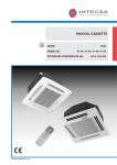
Bio Optica Milano S.p.A. • via San Faustino 58 • I-20134 Milano
Tel. +39 02.21.27.13.1 • Fax Acquisti/Export +39 02.21.54.155
Fax Assistenza/Contabilità +39 02.26.41.74.48 • Fax Vendite +39 02.21.53.000
Manuale d’uso e tecnico/ User and service manual 17-1770
BAGNO STENDIFETTE 1770
Codice: 17-1770
Revisione 120719 del 19/07/12
Pagina 1 di 27
Bio Optica Milano S.p.A. • via San Faustino 58 • I-20134 Milano
Tel. +39 02.21.27.13.1 • Fax Acquisti/Export +39 02.21.54.155
Fax Assistenza/Contabilità +39 02.26.41.74.48 • Fax Vendite +39 02.21.53.000
Manuale d’uso e tecnico/ User and service manual 17-1770
PRECAUZIONI D’USO
Prima di utilizzare lo strumento, leggere attentamente le istruzioni e le avvertenze
contenute nel presente manuale e conservarle per ogni ulteriore consultazione. Esse
forniscono indicazioni importanti per quanto riguarda la funzionalità e la sicurezza
nell’installazione, nell’uso e nella manutenzione.
La società Bio-Optica Milano S.p.A. non può essere considerata responsabile per
eventuali danni derivanti da usi impropri od erronei e per l’inosservanza di quanto
previsto da questo manuale e dalle vigenti norme di sicurezza.
1. Dopo aver tolto l’imballaggio assicurarsi che lo strumento si presenti integro senza visibili danneggiamenti che
potrebbero essere stati causati dal trasporto.
2. Prima di collegare lo strumento accertarsi che i dati di targa siano rispondenti a quelli della rete di distribuzione
elettrica.
3. Questo strumento deve essere destinato solo all’uso per il quale è stato espressamente concepito e cioè come
bagno stendifette in applicazioni di laboratorio. Ogni altro uso è da considerarsi improprio e quindi pericoloso.
4. Lo strumento deve essere utilizzato solo da personale autorizzato e professionalmente qualificato.
5. La manutenzione periodica annuale deve essere effettuata solo da personale qualificato e autorizzato da BioOptica. Per informazioni contattare il Servizio di Assistenza Tecnica Tel. 02-21271310.
6. La sicurezza elettrica di questo strumento è assicurata soltanto quando lo stesso è correttamente collegato ad un
efficace impianto di messa a terra come previsto dalle vigenti norme di sicurezza elettrica. E’ necessario verificare
questo fondamentale requisito di sicurezza e in caso di dubbio richiedere un controllo accurato dell’impianto. Lo
strumento è provvisto di un cavo di alimentazione a 2 cavi + terra da collegare alla presa di alimentazione.
7. Non rimuovere il telaio o parti di esso durante il funzionamento. Spegnere lo strumento e scollegarlo dalla presa
di alimentazione prima di procedere alla sua apertura. Questa operazione deve essere effettuata solo da personale
autorizzato e professionalmente qualificato.
8. Per eliminare il rischio di un cattivo funzionamento dello strumento, lo stesso deve operare in un ambiente privo di
forti campi elettromagnetici; ciò significa che trasmettitori quali telefoni cellulari non devono essere utilizzati nelle
vicinanze dello strumento.
In caso di grave malfunzionamento, spegnere lo strumento e contattare il Servizio di Assistenza Tecnica.
9. Tutti gli scarti e i rifiuti, sia infettivi sia radioattivi, derivanti dal ciclo di lavoro dello strumento devono essere
smaltiti in conformità con le leggi vigenti in materia.
Questa apparecchiatura è contrassegnata dal simbolo indicato a fianco, ai sensi della direttiva 2002/96/CE del
parlamento europeo e successive modifiche riguardanti i RAEE (Rifiuti di Apparecchiature Elettriche ed
Elettroniche). Ciò significa che è vietato smaltire questo apparecchio come un normale rifiuto; lo stesso deve invece
essere portato in un apposito centro di raccolta RAEE autorizzato e predisposto dalla Pubblica Amministrazione.
10. Il contenuto di questo manuale può essere soggetto a cambiamenti senza preavviso.
11. Si allega dichiarazione di conformità.
Revisione 120719 del 19/07/12
Pagina 2 di 27
Bio Optica Milano S.p.A. • via San Faustino 58 • I-20134 Milano
Tel. +39 02.21.27.13.1 • Fax Acquisti/Export +39 02.21.54.155
Fax Assistenza/Contabilità +39 02.26.41.74.48 • Fax Vendite +39 02.21.53.000
Manuale d’uso e tecnico/ User and service manual 17-1770
12. Simboli grafici presenti in etichetta (posizionata di fianco alla presa di alimentazione dello strumento):
Simbolo per NUMERO DI CATALOGO:
Simbolo per NUMERO DI SERIE:
Simbolo per CORRENTE ALTERNATA:
Simbolo per FUSIBILE:
Simbolo per CONSULTARE LE ISTRUZIONI PER L’USO:
Simbolo per MARCHIO CE:
Simbolo per DISPOSITIVO MEDICO DIAGNOSTICO IN VITRO:
Simbolo per SMALTIMENTO APPARECCHIATURE ELETTRICHE ED ELETTRONICHE:
Simbolo per DATA DI FABBRICAZIONE:
Simbolo per FABBRICANTE:
Revisione 120719 del 19/07/12
Pagina 3 di 27
Bio Optica Milano S.p.A. • via San Faustino 58 • I-20134 Milano
Tel. +39 02.21.27.13.1 • Fax Acquisti/Export +39 02.21.54.155
Fax Assistenza/Contabilità +39 02.26.41.74.48 • Fax Vendite +39 02.21.53.000
Manuale d’uso e tecnico/ User and service manual 17-1770
DESCRIZIONE
Bagno termostatato utilizzato per raccogliere e asciugare le sezioni di campioni istologici. Studiato per affiancare il
microtomo da laboratorio, è in grado di mantenere l’acqua alla temperatura desiderata in modo da far galleggiare e
distendere le sezioni in modo ottimale.
Caratteristiche dimensionali
Dimensioni (LxPxH):
350x365x155 mm.
Dimensioni piastra asciugavetrini (LxP):
350x100 mm.
Peso:
8 Kg.
Collegamenti elettrici
Alimentazione:
230V~ 50/60Hz.
Potenza:
350 Watt.
Fusibili:
N. 2 fusibili da 3,15 Ampere - 5x20 mm - T3.15AH250V.
Caratteristiche costruttive
Telaio in lamiera verniciata spessore 15/10.
Sonda NTC10K dotata di braccio mobile e dispositivo di sicurezza che interrompe l’alimentazione elettrica e il
riscaldamento della vasca quando si asporta la vaschetta.
Vaschetta pirex asportabile (capacità ca. 1,2 litri) per una semplice operazione di riempimento e svuotamento.
Una lampada neon da 6 Watt illumina la vasca per facilitare la raccolta delle sezioni.
Piastra asciugavetrini in grado di ospitare fino a 24 vetrini, situata nella parte posteriore.
Caratteristiche tecniche
Regolazione temperatura di lavoro Da +20°C a +70°C tramite termostato elettronico con microprocessore.
(Bagno stendifette):
Precisione di lettura ±1°C.
Controllo proporzionale della temperatura (PID).
Metodo
di
temperatura:
rilevazione
Modifica e visualizzazione
parametri di lavoro:
della
Tramite sonda NTC10K immersa direttamente nell’acqua.
dei
Tramite pannello di controllo con display digitale decimale.
Regolazione temperatura di lavoro
(Piastra asciugavetrini):
Da +20°C a +50°C tramite termostato manuale analogico.
Revisione 120719 del 19/07/12
Pagina 4 di 27
Bio Optica Milano S.p.A. • via San Faustino 58 • I-20134 Milano
Tel. +39 02.21.27.13.1 • Fax Acquisti/Export +39 02.21.54.155
Fax Assistenza/Contabilità +39 02.26.41.74.48 • Fax Vendite +39 02.21.53.000
Manuale d’uso e tecnico/ User and service manual 17-1770
Installazione
Posizionare lo strumento su un banco di lavoro piano e stabile e collegarlo alla presa elettrica (230V~ 50/60Hz)
utilizzando il cavo in dotazione.
Importante: Non utilizzare prolunghe o adattatori e non modificare il cavo in dotazione.
Revisione 120719 del 19/07/12
Pagina 5 di 27
Bio Optica Milano S.p.A. • via San Faustino 58 • I-20134 Milano
Tel. +39 02.21.27.13.1 • Fax Acquisti/Export +39 02.21.54.155
Fax Assistenza/Contabilità +39 02.26.41.74.48 • Fax Vendite +39 02.21.53.000
Manuale d’uso e tecnico/ User and service manual 17-1770
MODALITA’ D’USO
Istruzioni per il riempimento della vaschetta:
Tirare la sonda e ruotarla in senso orario (come indicato nell’immagine
a fianco).
Riempire la vaschetta con acqua distillata fino a metà livello.
Immergere la sonda nell’acqua.
Accendere lo strumento premendo l’interruttore principale verde. Sul display verrà visualizzata la temperatura
dell’acqua.
Impostazione temperatura Bagno Stendifette
Premere per ca. un secondo il TASTO 1 per visualizzare la temperatura impostata. Mantenendo premuto il TASTO
1 agire con i TASTI 2 o 3 per impostare il valore desiderato. Si consiglia di impostare la temperatura a ca. 40°C. Al
rilascio del TASTO 1 il nuovo valore viene memorizzato.
Il TASTO 4 serve per l’impostazione dei parametri (ad uso del servizio di assistenza tecnica).
Un LED rosso indica l’accensione e lo spegnimento della resistenza riscaldante.
Pannello frontale LTR-5 protezione IP55
Led rosso
TASTO 1
TASTO 2
TASTO 3
TASTO 4
Revisione 120719 del 19/07/12
Pagina 6 di 27
Bio Optica Milano S.p.A. • via San Faustino 58 • I-20134 Milano
Tel. +39 02.21.27.13.1 • Fax Acquisti/Export +39 02.21.54.155
Fax Assistenza/Contabilità +39 02.26.41.74.48 • Fax Vendite +39 02.21.53.000
Manuale d’uso e tecnico/ User and service manual 17-1770
Modifica parametri del termostato LAE
I parametri di funzionamento sono preimpostati secondo valori standard di riferimento e possono essere modificati.
Per accedere al menu di configurazione dei parametri, premere per 5 secondi i tasti 1 e 4.
Con i tasti 2 e 3 selezionare il parametro da modificare.
Una volta individuato il parametro che ci interessa, premere il tasto 1 per visualizzarne il valore.
Tenendo premuto il tasto, 1 agire con i tasti 2 e 3 per impostare il valore desiderato.
Al rilascio del tasto 1, il nuovo valore viene memorizzato e viene visualizzato il parametro successivo.
Per uscire dal setup premere il tasto 4 o attendere 30 secondi.
Parametro
Descrizione
Valore
SPL
Temperatura minima impostabile
20°C
SPH
Temperatura massima impostabile
70°C
OS1
Calibrazione sonda temperatura*
tra +01 e -02
*Lo scostamento medio tra la temperatura rilevata dalla sonda e la temperatura reale è minimo (± 1,5°C). Per
verificare il reale scostamento, portare l’acqua contenuta nella vaschetta a una temperatura di 40°C e misurare la
reale temperatura con un termometro digitale.
Se sul display del termostato la temperatura è di 40°C mentre il termometro digitale rileva una temperatura di 38°C,
togliere 2 al parametro OS1 per azzerare lo scostamento.
N.B. Per garantire l’ottimale funzionamento del controllo proporzionale (PID) non devono mai essere modificati i
valori relativi ai seguenti parametri: Pid, 1IT, 1DT, 1AR, 1CT.
Impostazione temperatura Piastra Asciugavetrini
Il riscaldamento della piastra viene avviato premendo l’interruttore principale verde; per escluderlo ruotare la
manopola del termostato in senso antiorario fino a fine corsa.
Lo strumento viene collaudato e preimpostato a una temperatura di ca. 40°C; per modificarla procedere nel modo
seguente:
1) Accendere lo strumento e attendere ca. 15 minuti.
2) Misurare la temperatura della piastra con un termometro o facendo asciugare qualche vetrino portaoggetto.
3) Regolare la temperatura ruotando la manopola nera, facendo piccoli movimenti intervallati da pause di ca. 10
minuti.
Revisione 120719 del 19/07/12
Pagina 7 di 27
Bio Optica Milano S.p.A. • via San Faustino 58 • I-20134 Milano
Tel. +39 02.21.27.13.1 • Fax Acquisti/Export +39 02.21.54.155
Fax Assistenza/Contabilità +39 02.26.41.74.48 • Fax Vendite +39 02.21.53.000
Manuale d’uso e tecnico/ User and service manual 17-1770
Pulizia
Prima di effettuare la pulizia, spegnere lo strumento e scollegare il cavo di alimentazione dalla presa di corrente.
Vaschetta pirex: utilizzare decalcificanti o acidi per il calcare, solventi per i residui di paraffina.
Telaio: utilizzare esclusivamente alcool o detergenti non aggressivi. Non utilizzare prodotti abrasivi o acidi al fine di
non rovinare le parti verniciate o in materiale plastico. Lo strumento non necessita di sterilizzazione, in quanto non è
previsto il trattamento di campioni freschi ma solo di campioni istologici fissati e inclusi in paraffina.
Manutenzione
La manutenzione periodica annuale deve essere effettuata da personale qualificato e autorizzato da Bio-Optica. Per
informazioni contattare il Servizio di Assistenza Tecnica Tel. 02-21271310.
Apertura dello strumento
Spegnere lo strumento e scollegare il cavo di alimentazione dalla presa di corrente. Rimuovere le viti del pannello
inferiore (i modelli più recenti sono assemblati con viti particolari, tipo TORX con foro centrale). Riposizionare lo
strumento sui piedini e ruotare la parte superiore verso sinistra (come indicato nell’ immagine).
Revisione 120719 del 19/07/12
Pagina 8 di 27
Bio Optica Milano S.p.A. • via San Faustino 58 • I-20134 Milano
Tel. +39 02.21.27.13.1 • Fax Acquisti/Export +39 02.21.54.155
Fax Assistenza/Contabilità +39 02.26.41.74.48 • Fax Vendite +39 02.21.53.000
Manuale d’uso e tecnico/ User and service manual 17-1770
Sostituzione fusibili
Se lo strumento non si accende, verificare il corretto inserimento del cavo di alimentazione, la presenza di corrente
nella rete e controllare che i due fusibili posti sotto la presa di corrente dell’apparecchio non siano bruciati.
Eventualmente sostituirli con altri di pari valore.
Presa di alimentazione porta fusibili (N. 2 fusibili ritardati da 3,15 Ampere - T3.15AH250V).
Modalità per la sostituzione: Spegnere lo strumento e scollegare il cavo di alimentazione dalla presa di corrente.
Fare una leggera pressione sul piccolo carter di plastica posto a copertura dei fusibili sotto l’ingresso
dell’alimentazione (se necessario aiutandosi con un piccolo cacciavite), procedere con la sostituzione dei fusibili,
richiudere il carter e verificare l’accensione dello strumento.
Aprire la scatola
portafusibili
con un cacciavite
Scatola portafusibili
aperta
Sostituzione lampada
Spegnere lo strumento e scollegare il cavo di alimentazione dalla presa di corrente.
Togliere il pannello sul fondo dello strumento svitando le 8 viti di fissaggio e sollevare il telaio ruotandolo verso
sinistra. Ruotare la lampada di 90° e sollevarla. Sostituirla con un modello analogo e ruotarla di 90°. Richiudere lo
strumento.
Sostituzione termostato LAE
Spegnere lo strumento e scollegare il cavo di alimentazione dalla presa di corrente, aprire lo strumento. Il termostato
è fissato con clip o staffe di bloccaggio. I collegamenti sono riportati nell’etichetta posizionata nella parte superiore
del termostato.
Revisione 120719 del 19/07/12
Pagina 9 di 27
Bio Optica Milano S.p.A. • via San Faustino 58 • I-20134 Milano
Tel. +39 02.21.27.13.1 • Fax Acquisti/Export +39 02.21.54.155
Fax Assistenza/Contabilità +39 02.26.41.74.48 • Fax Vendite +39 02.21.53.000
Manuale d’uso e tecnico/ User and service manual 17-1770
GUIDA ALLA SOLUZIONE DEI PROBLEMI
Lo strumento non si accende
Verificare il corretto inserimento del cavo, la presenza di corrente nella rete e che l’alimentazione sia corretta.
Controllare il funzionamento dei fusibili e sostituirli, se necessario.
Lo strumento si accende ma i tasti non rispondono ai comandi
E’ possibile che, dopo un certo periodo di utilizzo, la membrana che copre i tasti si possa deformare e bloccare.
Sostituire il termoregolatore LAE.
Lo strumento si accende ma il termostato non si accende e la resistenza non scalda
Il braccio inox a “L” che contiene la sonda temperatura nella posizione di lavoro chiude un microswitch che alimenta
il termostato. Verificare il funzionamento del micro, il corretto posizionamento e fissaggio del dischetto interno.
Nel display compare una segnalazione di errore (ad esempio DL1)
Verificare il corretto collegamento della sonda temperatura.
La vasca non si scalda
Il termostato segnala con un punto rosso la chiusura del circuito e quindi l’alimentazione della resistenza.
Se il led rosso non si accende, verificare i parametri del termostato. Se, invece, si accende controllare
l’alimentazione e il funzionamento della resistenza riscaldante.
La piastra superiore asciugavetrini non scalda
Verificare il corretto funzionamento del termostato analogico e il collegamento dei cablaggi.
Controllare l’alimentazione e il funzionamento della resistenza riscaldante.
La lampada non funziona
Sostituire la lampada o lo starter.
Revisione 120719 del 19/07/12
Pagina 10 di 27
Bio Optica Milano S.p.A. • via San Faustino 58 • I-20134 Milano
Tel. +39 02.21.27.13.1 • Fax Acquisti/Export +39 02.21.54.155
Fax Assistenza/Contabilità +39 02.26.41.74.48 • Fax Vendite +39 02.21.53.000
Manuale d’uso e tecnico/ User and service manual 17-1770
PRINCIPALI COMPONENTI
CODICE
DESCRIZIONE
Q.TA’
17-1771N
VASCHETTA PIREX
1
37-AR09E2F6A
FILTRO RETE 6 AMPERE
1
37-COP1770
COPERCHIO BIANCO IN OPALINA
1
37-MOL1770
MOLLA ACCIAIO
1
37-OPA220X30
OPALINA BIANCA
1
37-129-432
INTERRUTTORE IMPERMEABILE VERDE
1
37-1004
RESISTENZA 50 WATT
1
37-1005
TUBO A 90° PER SONDA
1
37-1006/A
POMELLO CON PERNO
1
37-1006/B
POMOLO FILETTATO
1
37-1006/C
DISCHETTO ∅ 30x10
1
37-1007
MICROSWITCH
1
37-1008
GHIERA
1
37-1011
PORTALAMPADA
2
37-1012
STARTER UNIVERSALE
1
37-1012P
PORTASTARTER
1
37-1013
REATTORE
1
37-1014
LAMPADA NEON
1
37-1023
PIEDINI IN GOMMA
4
37-1028
STAFFA
1
37-1040/N
TERMOREGOLATORE DIGITALE
1
37-RELE1040
RELE’
1
37-1045
CAVO ALIMENTAZIONE
1
37-2090
TERMOSTATO
1
37-4090
PANNELLO POLICARBONATO
1
37-6010
RESISTENZA IN MICA
1
37-1020/1
SCOCCA SUPERIORE
1
37-1020/2
PIASTRA PORTAVETRINI NERA
1
37-1020/3
PIASTRA PORTAVETRINI INTERNA
1
37-1020/4
VASCHETTA PORTAPIREX NERA
1
37-1020/5
VASCHETTA PORTAPIREX INTERNA
1
37-1020/6
PANNELLO INFERIORE
1
MU17-1770
MANUALE D’USO
1
Revisione 120719 del 19/07/12
Pagina 11 di 27
Bio Optica Milano S.p.A. • via San Faustino 58 • I-20134 Milano
Tel. +39 02.21.27.13.1 • Fax Acquisti/Export +39 02.21.54.155
Fax Assistenza/Contabilità +39 02.26.41.74.48 • Fax Vendite +39 02.21.53.000
Manuale d’uso e tecnico/ User and service manual 17-1770
Vista frontale e posteriore dello strumento
Revisione 120719 del 19/07/12
Pagina 12 di 27
Bio Optica Milano S.p.A. • via San Faustino 58 • I-20134 Milano
Tel. +39 02.21.27.13.1 • Fax Acquisti/Export +39 02.21.54.155
Fax Assistenza/Contabilità +39 02.26.41.74.48 • Fax Vendite +39 02.21.53.000
Manuale d’uso e tecnico/ User and service manual 17-1770
Circuito elettrico
Revisione 120719 del 19/07/12
Pagina 13 di 27
Bio Optica Milano S.p.A. • via San Faustino 58 • I-20134 Milano
Tel. +39 02.21.27.13.1 • Fax Acquisti/Export +39 02.21.54.155
Fax Assistenza/Contabilità +39 02.26.41.74.48 • Fax Vendite +39 02.21.53.000
Manuale d’uso e tecnico/ User and service manual 17-1770
WATER BATH 1770
Code: 17-1770
Revisione 120719 del 19/07/12
Pagina 14 di 27
Bio Optica Milano S.p.A. • via San Faustino 58 • I-20134 Milano
Tel. +39 02.21.27.13.1 • Fax Acquisti/Export +39 02.21.54.155
Fax Assistenza/Contabilità +39 02.26.41.74.48 • Fax Vendite +39 02.21.53.000
Manuale d’uso e tecnico/ User and service manual 17-1770
USE PRECAUTIONS
Before using the instrument, read carefully the instructions and warnings contained in
this manual and keep it for further reference. They supply important indications regarding
the functions and safety for installing, using and maintaining the instrument.
Bio-Optica Milano S.p.A. cannot be held responsible for any damage caused by improper
or incorrect use and by the non-observance of any of the prescription provided in this
manual and by the safety regulations in force.
1. After unpacking, make sure that the instrument is complete and not damaged by transport.
2. Before connecting the instrument to the power supply make sure that its rating corresponds to that of the power
supply.
3. This instrument must only be used for the purpose for which it was designed, that is, as a water bath for laboratory
use. Any other use is to be considered improper and therefore hazardous.
4. The instrument must only be used by authorized and professionally qualified technician.
5. The electrical safety of this instrument can be guaranteed only if it is correctly connected to an efficient earth
circuit as indicated by current electrical safety regulations. It is necessary to check this fundamental safety
prerequisite, and if in doubt, ask to check the circuit. The instrument is provided with a power supply cable having 2
wires + ground tap that have to be connected to the power supply socket.
6. Do not remove the chassis or parts of it during operation. Switch off the instrument and disconnect the power
supply cable before opening it. This operation must to be effected only by authorized and professionally qualified
technician.
7. To eliminate instrument malfunctioning risks, do not work near strong magnetic fields and do not use transmitters
such as cellular phones near the instrument. In case of serious malfunctioning switch off the instrument and contact
the Technical Assistance Service.
8. All waste material, both infectious and radioactive, deriving from the appliance working cycle must be disposed in
compliance with the regulation in force.
This appliance is marked from this symbol, in compliance with EU directive 2002/96/CE regarding
electric and electronic appliances waste. This mean that the instrument, at the end of its useful life, must be
collected separately from other refuse. The user must deliver it to the special differentiated refuse collection centres,
that are predisposed by the public authority.
9. The contents of this manual is subject to change without further notice.
10. Please find enclosed the declaration of conformity.
Revisione 120719 del 19/07/12
Pagina 15 di 27
Bio Optica Milano S.p.A. • via San Faustino 58 • I-20134 Milano
Tel. +39 02.21.27.13.1 • Fax Acquisti/Export +39 02.21.54.155
Fax Assistenza/Contabilità +39 02.26.41.74.48 • Fax Vendite +39 02.21.53.000
Manuale d’uso e tecnico/ User and service manual 17-1770
11. Graphic symbols indicated on the label (positioned near the instrument’s power supply socket):
Symbol for CATALOGUE NUMBER:
Symbol for SERIAL NUMBER:
Symbol for ALTERNATING CURRENT:
Symbol for FUSE:
Symbol for CONSULT THE INSTRUCTIONS:
Symbol for EC MARK:
Symbol for IN VITRO DIAGNOSTIC-MEDICAL DEVICE:
Symbol for DISPOSAL OF ELECTRIC AND ELECTRONIC EQUIPMENT:
Symbol for DATE OF MANUFACTURE:
Symbol for MANUFACTURER:
Revisione 120719 del 19/07/12
Pagina 16 di 27
Bio Optica Milano S.p.A. • via San Faustino 58 • I-20134 Milano
Tel. +39 02.21.27.13.1 • Fax Acquisti/Export +39 02.21.54.155
Fax Assistenza/Contabilità +39 02.26.41.74.48 • Fax Vendite +39 02.21.53.000
Manuale d’uso e tecnico/ User and service manual 17-1770
DESCRIPTION
Thermostated bath used to collect and dry histological samples sections. Designed to be used together with the
laboratory microtome, it maintains the water temperature at the desired level so that the sections can be handled
properly.
Dimensional features
Dimensions (WxDxH):
350x365x155 mm.
Slide-dryer plate dimensions (WxD):
350x100 mm.
Weight:
8 Kg.
Electrical connections
Power supply:
230V~ 50/60Hz.
Power:
350 Watt.
Fuses:
N. 2 fuses of 3,15 Ampere - 5x20 mm - T3.15AH250V.
Structural features
Thickness 15/10 painted sheet steel chassis.
NTC10K probe provided with articulated arm and safety device that cut off the power supply and the basin
heating when the basin is removed.
Removable pirex basin (capacity ca. 1,2 litres) for a simple operation of filling and emptying.
A 6 Watt neon lamp illuminates the basin in order to facilitate the sections collecting.
Slide-dryer plate that can house up to 24 slides, situated on the back side.
Technical features
Working temperature
(Water bath):
adjustment From +20°C to +70°C through electronic thermostat with microprocessor.
Reading precision ±1°C.
Control proportional of the temperature (PID).
Temperature taking system:
Through NTC10K probe immersed directly in water.
Working parameters
and modification:
visualization
Through control panel with decimal digital display.
Working temperature
(Slide-dryer plate):
adjustment
From +20°C to +50°C through analogic manual thermostat.
Revisione 120719 del 19/07/12
Pagina 17 di 27
Bio Optica Milano S.p.A. • via San Faustino 58 • I-20134 Milano
Tel. +39 02.21.27.13.1 • Fax Acquisti/Export +39 02.21.54.155
Fax Assistenza/Contabilità +39 02.26.41.74.48 • Fax Vendite +39 02.21.53.000
Manuale d’uso e tecnico/ User and service manual 17-1770
Installation
Position the instrument on a level and stable working bench and connect it to the power supply socket (230V~
50/60Hz) using the provided cable.
Important: Do not use any extension or adapter and do not modify the provided cable.
Revisione 120719 del 19/07/12
Pagina 18 di 27
Bio Optica Milano S.p.A. • via San Faustino 58 • I-20134 Milano
Tel. +39 02.21.27.13.1 • Fax Acquisti/Export +39 02.21.54.155
Fax Assistenza/Contabilità +39 02.26.41.74.48 • Fax Vendite +39 02.21.53.000
Manuale d’uso e tecnico/ User and service manual 17-1770
USE
Instructions for the basin filling:
Pull the probe and rotate it clockwise (as shown in the picture).
Fill the basin with distilled water up to half level.
Immerse the probe in the water.
Switch on the instrument by pressing the green main switch. The water temperature will appear on the display.
Setting the Water Bath’s temperature
Press BUTTON 1 for ca. one second in order to visualize the set temperature. By keeping BUTTON 1 pressed, use
BUTTONS 2 or 3 to set the desired value. We suggest to set it at ca. 40°C. When BUTTON 1 is released, the new
value is stored.
BUTTON 4 is used by technical assistance service to set the parameters.
A red LED shows ignition and switching off of the heating resistance.
Frontal panel LTR-5 protection IP55
Red led
BUTTON 1
BUTTON 2
BUTTON 3
BUTTON 4
Revisione 120719 del 19/07/12
Pagina 19 di 27
Bio Optica Milano S.p.A. • via San Faustino 58 • I-20134 Milano
Tel. +39 02.21.27.13.1 • Fax Acquisti/Export +39 02.21.54.155
Fax Assistenza/Contabilità +39 02.26.41.74.48 • Fax Vendite +39 02.21.53.000
Manuale d’uso e tecnico/ User and service manual 17-1770
Changing the LAE thermostat parameters
Working parameters are preset according to reference standard values and can be modified.
In order to access the setup menu, press keys 1 and 4 for 5 seconds.
Select the parameter to modify using keys 2 and 3.
After choosing the interested parameter, press key 1 to visualize the value.
By keeping key 1 pressed, use keys 2 and 3 to set the desired value.
When key 1 is released, the new value is saved and the next parameter is visualized.
In order to exit from the setup, press key 4 or wait for 30 seconds.
Parameter
Description
Value
SPL
Minimum temperature that can be set
20°C
SPH
Maximum temperature that can be set
70°C
OS1
Calibration of temperature probe*
between +01 and -02
*The standard deviation between the temperature shown by the probe and the real temperature is minimum (±
1,5°C). In order to verify the real deviation, let the water contained in the basin reach the temperature of 40°C and
measure the real temperature with a digital thermometer.
If the temperature on the thermostat display is 40°C whereas the digital thermometer shows 38°C, subtract 2 from
ADJ parameter in order to zero the deviation.
N.B. In order to guarantee the optimal working of the control proportional (PID) must not be modified the values
relative to the following parameters: Pid, 1IT, 1DT, 1AR, 1CT.
Setting the Slide-Dryer Plate’s temperature
The plate heating starts by pressing the green main switch; to exclude it, rotate the thermostat knob anticlockwise up
to end-run.
The instrument is tested and preset at a temperature of ca. 40°C; to modify it proceed as follows:
1) Switch on the instrument and wait ca. 15 minutes.
2) Measure the plate temperature with a thermometer or letting some slide dry.
3) Adjust the temperature rotating the black knob, making little movements with pauses of ca. 10 minutes.
Revisione 120719 del 19/07/12
Pagina 20 di 27
Bio Optica Milano S.p.A. • via San Faustino 58 • I-20134 Milano
Tel. +39 02.21.27.13.1 • Fax Acquisti/Export +39 02.21.54.155
Fax Assistenza/Contabilità +39 02.26.41.74.48 • Fax Vendite +39 02.21.53.000
Manuale d’uso e tecnico/ User and service manual 17-1770
Cleaning
Before effecting the cleaning, switch off the instrument and unplug the cable from the socket.
Pirex basin: use decalcifying products or acids for limescale, solvents for residual paraffin.
Chassis: use only alcohol or non-aggressive detergents. Do not use abrasive products or acids in order to avoid
ruining the varnished or plastic parts. The instrument does not need to be sterilized because is not expected the
treatment of fresh samples but only of histological samples fixed and included in paraffin.
Maintenance
Effect the periodic cleaning.
Opening the instrument
Switch off the instrument and unplug the cable from the socket. Remove the screws of the lower panel (the most
recent models are assembled with special screws, type TORX with central hole). Replace the instrument on the feet
and rotate the upper side towards left (as shown in the image).
Revisione 120719 del 19/07/12
Pagina 21 di 27
Bio Optica Milano S.p.A. • via San Faustino 58 • I-20134 Milano
Tel. +39 02.21.27.13.1 • Fax Acquisti/Export +39 02.21.54.155
Fax Assistenza/Contabilità +39 02.26.41.74.48 • Fax Vendite +39 02.21.53.000
Manuale d’uso e tecnico/ User and service manual 17-1770
Replacing the fuses
If the instrument doesn’t start, check that the electric cable has been connected properly, there is current and the
two fuses under the instrument’s socket aren’t burnt. If necessary, change them with fuses of identic value.
Fuses holder socket (N. 2 delayed fuses of 3,15 Ampere - T3.15AH250V).
Instructions for the replacement: Switch off the appliance and unplug the cable from the socket. Make a light
pressure on the little carter covering the fuses (if necessary using a little screwdriver), change them, close the carter
and check the instrument’s ignition.
Open the fuses box
using a screwdriver
Fuse box opened
Replacing the lamp
Switch off the instrument and unplug the cable from the socket.
Remove the panel at the bottom of the instrument unscrewing the 8 fixing screws and lift the chassis rotating it on
the left. Rotate the lamp of 90° and lift it. Change it with an equal model and rotate it of 90°. Close the instrument
again.
Replacing LAE thermostat
Switch off the instrument and unplug the power supply cable from the socket, open the instrument. The thermostat is
fixed with clips or blocking flasks. The connections are on the label positioned on the upper side of the thermostat.
Revisione 120719 del 19/07/12
Pagina 22 di 27
Bio Optica Milano S.p.A. • via San Faustino 58 • I-20134 Milano
Tel. +39 02.21.27.13.1 • Fax Acquisti/Export +39 02.21.54.155
Fax Assistenza/Contabilità +39 02.26.41.74.48 • Fax Vendite +39 02.21.53.000
Manuale d’uso e tecnico/ User and service manual 17-1770
TROUBLE SHOOTING
The instrument doesn’t switch on
Check that the cable is fixed correctly, there is current in the electric system and the power supply is correct.
Check the fuses working and change them, if necessary.
The instrument lights up but the keys doesn’t respond to controls
It is possible that, after some time, the membrane covering the keys warps and blocks the keys. Replace the
thermoregulator LAE.
The instrument lights up but the thermostat doesn’t light up and the resistance doesn’t heat
The “L”-shaped stainless steel arm containing the temperature probe in the working position close a microswitch that
feeds the thermostat. Verify the microswitch working, the correct positioning and fixing of the internal disk.
An error signal (for example DL1) appears on the display
Verify the correct connection of the temperature probe.
The basin doesn’t heat
The thermostat indicates with a red point the circuit closing and so the resistance power supply.
If the red led doesn’t light up, verify the thermostat parameters. If, on the contrary, it lights up check the power
supply and the working of the heating resistance.
The slide-dryer upper plate doesn’t heat
Verify the correct working of the analogic thermostat and the connection of the wiring.
Check the power supply and the working of the heating resistance.
The lamp doesn’t work
Replace the lamp or the starter.
Revisione 120719 del 19/07/12
Pagina 23 di 27
Bio Optica Milano S.p.A. • via San Faustino 58 • I-20134 Milano
Tel. +39 02.21.27.13.1 • Fax Acquisti/Export +39 02.21.54.155
Fax Assistenza/Contabilità +39 02.26.41.74.48 • Fax Vendite +39 02.21.53.000
Manuale d’uso e tecnico/ User and service manual 17-1770
MAIN COMPONENTS
CODE
DESCRIPTION
QUANTITY
pirex basin
1
37-AR09E2F6A
6 ampere wire filter
1
37-COP1770
opaline white cover
1
37-MOL1770
steel spring
1
white opaline
1
green waterproof switch
1
37-1004
50 watt resistance
1
37-1005
90° tube for feeler
1
37-1006/A
knob with pin
1
37-1006/B
threaded knob
1
37-1006/C
∅ 30x10 disk
1
37-1007
microswitch
1
37-1008
metal ring
1
37-1011
lamp holder
2
37-1012
universal starter
1
starter holder
1
reactor
1
37-1014
neon lamp
1
37-1023
rubber feets
4
37-1028
stirrup
1
digital thermoregulator
1
relay
1
37-1045
power supply cable
1
37-2090
thermostat
1
37-4090
polycarbonate panel
1
37-6010
17-1771N
37-OPA220X30
37-129-432
37-1012P
37-1013
37-1040/N
37-RELE1040
mica resistance
1
37-1020/1
upper chassis
1
37-1020/2
black slide holder plate
1
37-1020/3
internal slide holder plate
1
37-1020/4
black pirex holder dish
1
37-1020/5
internal pirex holder dish
1
37-1020/6
lower panel
1
MU17-1770
user manual
1
Revisione 120719 del 19/07/12
Pagina 24 di 27
Bio Optica Milano S.p.A. • via San Faustino 58 • I-20134 Milano
Tel. +39 02.21.27.13.1 • Fax Acquisti/Export +39 02.21.54.155
Fax Assistenza/Contabilità +39 02.26.41.74.48 • Fax Vendite +39 02.21.53.000
Manuale d’uso e tecnico/ User and service manual 17-1770
Instrument back and frontal view
Revisione 120719 del 19/07/12
Pagina 25 di 27
Bio Optica Milano S.p.A. • via San Faustino 58 • I-20134 Milano
Tel. +39 02.21.27.13.1 • Fax Acquisti/Export +39 02.21.54.155
Fax Assistenza/Contabilità +39 02.26.41.74.48 • Fax Vendite +39 02.21.53.000
Manuale d’uso e tecnico/ User and service manual 17-1770
Electric wiring diagram
Revisione 120719 del 19/07/12
Pagina 26 di 27
Bio Optica Milano S.p.A. • via San Faustino 58 • I-20134 Milano
Tel. +39 02.21.27.13.1 • Fax Acquisti/Export +39 02.21.54.155
Fax Assistenza/Contabilità +39 02.26.41.74.48 • Fax Vendite +39 02.21.53.000
Manuale d’uso e tecnico/ User and service manual 17-1770
Milano, 19 luglio 2012
DICHIARAZIONE DI CONFORMITA’ / DECLARATION OF CONFORMITY
KONFORMITÄTSERKLÄRUNG / DECLARATION DE CONFORMITE
Nome e indirizzo della ditta
Name and address of the firm
Name und Adresse der Firma
Nom et adresse de l’enterprise
BIO OPTICA Milano S.p.A.
Via S.Faustino, 58
20134 MILANO
C.F./P.IVA 06754140157
Dichiariamo sotto la nostra responsabilità che / We declare under our sole responsibility that
Wir erklären in alleiniger Verantwortung, dass / Nous declarons sous notre propre responsabilitè que
il dispositivo medico-diagnostico in vitro
the in vitro diagnostic medical device
das Medizinprodukt für die In-vitro_Diagnostik
le dispositif mèdical de diagnostic in vitro
della classe:
of class:
der Klasse:
de la classe:
BAGNO STENDIFETTE/WATER BATH 1770
Altro
Other
Sonstiges produrti
Autre
soddisfa tutte le disposizioni della direttiva 98/79/CE e successive modifiche ed integrazioni che lo riguardano
meets all the provisions of the directive 98/79/EC and following amendment which apply to it
allen Anforderungen der Richtlinie 98/79/EG entspricht, die anwendbar sind
remplit toutes les exigences de la directive 98/79/CE et modification qui lui sont applicables
Norme nazionali o armonizzate applicate
Applied harmonised standards and National standards
Angewandte harmonisierte Normen, nationale Normen
Normes harmonisées et normes nationales
−
−
−
−
−
−
−
EN 375
EN 980
EN ISO 14971
EN 60601-1-2
EN 61010-1
EN 61010-2-101
EN 61010-2-010
Edizione in vigore alla data di emissione del documento/Current
ed. at document date/Aktuelle Ausgabe am belegdatum/Édition
actuelle à la date du document
BIO-OPTICA MILANO SPA
Legale Rappresentante
Carlo Sbona
Revisione 120719 del 19/07/12
Pagina 27 di 27