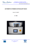
1
Bio Optica Milano S.p.A. • via San Faustino 58 • I-20134 Milano
Tel. +39 02.21.27.13.1 • Fax Acquisti/Export +39 02.21.54.155
Fax Assistenza/Contabilità +39 02.26.41.74.48 • Fax Vendite +39 02.21.53.000
User and service manual ReceivingBench
RECEIVING BENCH
Codes: 19-500/1000, 19-500/2000
Revision 120614 of 14/06/12
Page 1 of 21
Bio Optica Milano S.p.A. • via San Faustino 58 • I-20134 Milano
Tel. +39 02.21.27.13.1 • Fax Acquisti/Export +39 02.21.54.155
Fax Assistenza/Contabilità +39 02.26.41.74.48 • Fax Vendite +39 02.21.53.000
User and service manual ReceivingBench
USE PRECAUTIONS
Before using the instrument, read carefully the instructions and warnings contained in
this manual and keep it for further reference. They supply important indications regarding
the functions and safety for installing, using and maintaining the instrument.
Bio-Optica Milano S.p.A. cannot be held responsible for any damage caused by improper
or incorrect use and by the non-observance of any of the prescription provided in this
manual and by the safety regulations in force.
1. After unpacking, make sure that the instrument is complete and not damaged by transport.
2. Before connecting the instrument to the power supply make sure that its rating corresponds to that of the power
supply.
3. This instrument must only be used for the purpose for which it was designed, that is, as bench for histology for
laboratory use. Any other use is to be considered improper and therefore hazardous.
4. The instrument must only be used by authorized and professionally qualified technician.
5. The electrical safety of this instrument can be guaranteed only if it is correctly connected to an efficient earth
circuit as indicated by current electrical safety regulations. It is necessary to check this fundamental safety
prerequisite, and if in doubt, ask to check the circuit. The instrument is provided with a power supply cable having 2
wires + ground tap that have to be connected to the power supply socket.
6. Do not remove the chassis or parts of it during operation. Switch off the instrument and disconnect the power
supply cable before opening it. This operation must to be effected only by authorized and professionally qualified
technician.
7. To eliminate instrument malfunctioning risks, do not work near strong magnetic fields and do not use transmitters
such as cellular phones near the instrument. In case of serious malfunctioning switch off the instrument and contact
the Technical Assistance Service.
8. All waste material, both infectious and radioactive, deriving from the appliance working cycle must be disposed in
compliance with the regulation in force.
This appliance is marked from this symbol, in compliance with EU directive 2002/96/CE regarding
electric and electronic appliances waste. This mean that the instrument, at the end of its useful life, must be
collected separately from other refuse. The user must deliver it to the special differentiated refuse collection centres,
that are predisposed by the public authority.
9. The contents of this manual is subject to change without further notice.
10. Please find enclosed the declaration of conformity.
Revision 120614 of 14/06/12
Page 2 of 21
Bio Optica Milano S.p.A. • via San Faustino 58 • I-20134 Milano
Tel. +39 02.21.27.13.1 • Fax Acquisti/Export +39 02.21.54.155
Fax Assistenza/Contabilità +39 02.26.41.74.48 • Fax Vendite +39 02.21.53.000
User and service manual ReceivingBench
11. Graphic symbols indicated on the label (positioned near the instrument’s power supply socket):
Symbol for CATALOGUE NUMBER:
Symbol for SERIAL NUMBER:
Symbol for ALTERNATING CURRENT:
Symbol for FUSE:
Symbol for CONSULT THE INSTRUCTIONS:
Symbol for EC MARK:
Symbol for IN VITRO DIAGNOSTIC-MEDICAL DEVICE:
Symbol for DISPOSAL OF ELECTRIC AND ELECTRONIC EQUIPMENT:
Symbol for DATE OF MANUFACTURE:
Symbol for MANUFACTURER:
Revision 120614 of 14/06/12
Page 3 of 21
Bio Optica Milano S.p.A. • via San Faustino 58 • I-20134 Milano
Tel. +39 02.21.27.13.1 • Fax Acquisti/Export +39 02.21.54.155
Fax Assistenza/Contabilità +39 02.26.41.74.48 • Fax Vendite +39 02.21.53.000
User and service manual ReceivingBench
INDEX
1) Technical features.
Page 5
2) Installation.
Page 7
3) Electric connections.
Page 7
4) Aspiration system.
Page 7
5) Replacement of filter.
Page 8
6) Control panel.
Page 9
7) Replacing the neon lamp.
Page 15
8) Replacing the fuses.
Page 16
9) Cleaning and maintenance.
Page 17
10) Main components.
Page 18
11) Electric wiring diagram.
Page 19
12) Declaration of conformity.
Page 21
Revision 120614 of 14/06/12
Page 4 of 21
Bio Optica Milano S.p.A. • via San Faustino 58 • I-20134 Milano
Tel. +39 02.21.27.13.1 • Fax Acquisti/Export +39 02.21.54.155
Fax Assistenza/Contabilità +39 02.26.41.74.48 • Fax Vendite +39 02.21.53.000
User and service manual ReceivingBench
1) TECHNICAL FEATURES
Aspirated bench designed to hold and store disposable containers during reporting of histological samples
preserved in formalin.
Provided with fumes aspiration system from the supporting surface and the frontal side; predisposed for fumes
discharge outside.
Electrical connections
Power supply:
230V~ 50/60Hz.
Rated output:
1 Kw.
Nominal current:
6,3A with delayed fuses.
Power supply socket:
Placed at a height of 1200 mm, it can be on the right or on the left depending on
the position of the aspiration collector (it is on the opposite side compared with the
collector).
Emergency power supply:
Not necessary.
Remote exit:
Remote exit from card.
Fuses:
See paragraph 8) Fuses replacement on page 16.
Other connections
Water connections:
Not necessary.
Fumes discharge:
The bench is provided with ∅ 200 mm collector on its upper side in order to allow
the connection to the hospital’s centralized canalization system. The collector is
placeable on request on the right or on the left.
Lighting
N. 1 Neon (N. 2 for models 19-500/2000) - 30 Watt, protection IP20 – placed in the upper frontal side.
Structural features
Structure made entirely of satinized, thickness 12/10, AISI 304 stainless steel with smooth surface and rounded
edges (in compliance with the regulation in force).
6/7 mm accident prevention, satinized, stratified side glasses in order to avoid draughts near the working
surface and contain fumes.
Base with doors.
Antistatic and antislip adjustable feet allow to get a perfect horizontal position of the working surface.
Noise level < 56 dB (A).
Revision 120614 of 14/06/12
Page 5 of 21
Bio Optica Milano S.p.A. • via San Faustino 58 • I-20134 Milano
Tel. +39 02.21.27.13.1 • Fax Acquisti/Export +39 02.21.54.155
Fax Assistenza/Contabilità +39 02.26.41.74.48 • Fax Vendite +39 02.21.53.000
User and service manual ReceivingBench
Working surface features
Weldings-free, thickness 12/10, AISI 304 stainless steel surface, provided with liquids containing rim.
Large aspirated basin to collect incidental liquid leaks, covered by two removable perforated tops (three for
models 19-500/2000) - holes of ∅ 7 mm - which serve as a supporting surface.
Dimensional features in mm
Overall dimensions
Working usable dimensions
RECEIVING BENCH
WxDxH in mm
Weight
WxDxH in mm
19-500/1000
1000x750x1200
100 kg
900x650x900
19-500/2000
2000x750x1200
190 kg
1900x650x900
Revision 120614 of 14/06/12
Page 6 of 21
Bio Optica Milano S.p.A. • via San Faustino 58 • I-20134 Milano
Tel. +39 02.21.27.13.1 • Fax Acquisti/Export +39 02.21.54.155
Fax Assistenza/Contabilità +39 02.26.41.74.48 • Fax Vendite +39 02.21.53.000
User and service manual ReceivingBench
2) INSTALLATION
During the unpacking and positioning manoeuvring, proceed cautiously in order to avoid possible damages. Apply
the two glass parts in the proper side seats.
In case of connection to a canalization system for fumes expulsion outside, the bench must be positioned so that it is
possible to carry out the discharged air.
3) ELECTRIC CONNECTIONS
Before connecting the instrument to the electric system using the provided cable, verify the adequacy of the electric
line, the existence of ground tap and the compliance of the electric system with the law in force.
Important: Do not use any extension or adapter and do not modify the provided cable.
4) ASPIRATION SYSTEM
The bench is provided with:
N. 1 anti-spark three-phase electrofan (N. 2 for models 19-500/2000) adjustable through inverter (preinstalled).
N. 1 synthetic fibres prefilter (preinstalled) to retain possible impurities and improve the filter’s efficiency.
N. 1 filter for formalin (preinstalled), whose replacement happens from the lower side simply and cleanly.
The bench is provided with ∅ 200 mm collector on its upper side in order to allow the connection to the
hospital’s centralized canalization system for fumes discharge outside.
The electrofan allows fumes aspiration from the perforated supporting surface and the frontal grid. The air
is purified passing through prefilter and filter and can be discharged in this way:
1) FAN PREFILTER + 2 FILTERS DISCHARGE IN THE SAME ROOM.
Important: In case of discharge in the same room, it is necessary to install two filters in order to guarantee an effective
removal of the polluting substances. In this way it is guaranteed the filter’s efficacy of 100% as the residence time (Tr) of the
aspirated flow will be higher than 0,1 second.
2) FAN PREFILTER + FILTER DISCHARGE OUTSIDE THROUGH A NON-ASPIRATED CANALIZATION SYSTEM
(draining pipe not longer than 3 metres, with diameter of 200 mm).
3) FAN PREFILTER + FILTER DISCHARGE OUTSIDE THROUGH AN ASPIRATED CANALIZATION SYSTEM.
Important:
- In case of non-aspirated canalization, the length of the draining pipe must not be higher than 3 metres, the
diameter must be equal to 200 mm.
Revision 120614 of 14/06/12
Page 7 of 21
Bio Optica Milano S.p.A. • via San Faustino 58 • I-20134 Milano
Tel. +39 02.21.27.13.1 • Fax Acquisti/Export +39 02.21.54.155
Fax Assistenza/Contabilità +39 02.26.41.74.48 • Fax Vendite +39 02.21.53.000
User and service manual ReceivingBench
5) REPLACEMENT OF FILTER
The control panel is provided with a digital timer preset at 600 hours (filter’s middle life). When this value is reached
a visual and acoustic alarm enters into action to advise the operator to change the filter.
For the replacement proceed in the following way:
1) Switch off the instrument and unplug the cable form the socket.
2) Wear individual protection devices in compliance with the regulation in force.
3) Remove the frontal panel unscrewing the four knobs, unscrew the screws of the case and remove the internal
panel.
4) Extract the consumed filter and prefilter and replace them with identical filter and prefilter.
5) Replace the internal panel, screw the screws of the case and replace the frontal panel screwing the four knobs.
6) Dispose the consumed filter and prefilter in compliance with the regulation in force.
In case of accidental infiltration of liquids or foreign bodies in the filter area, contact the Technical Assistance Service
immediately and do not use the bench.
Filter
Prefilter
Revision 120614 of 14/06/12
Page 8 of 21
Bio Optica Milano S.p.A. • via San Faustino 58 • I-20134 Milano
Tel. +39 02.21.27.13.1 • Fax Acquisti/Export +39 02.21.54.155
Fax Assistenza/Contabilità +39 02.26.41.74.48 • Fax Vendite +39 02.21.53.000
User and service manual ReceivingBench
6) CONTROL PANEL
Control panel - with polycarbonate soft-touch keyboard and digital display - for the working parameters visualization
and modification.
Main functions
General ignition switch.
Emergency switch.
Start/stop switch for aspiration working.
Germicidal U.V. lamp switch (this function is not active).
Neon switch.
Adjustable halogen spotlights switch (this function is not active).
Aspiration speed regulation.
Red LED visual alarm and BUZZER acoustic alarm for filters saturation.
Acoustic alarms silencing key.
Working parameters change key.
Electric frontal glass ascent/descent key (this function is not active).
Bench ignition and switching off programming.
Filter’s change programming.
Revision 120614 of 14/06/12
Page 9 of 21
Bio Optica Milano S.p.A. • via San Faustino 58 • I-20134 Milano
Tel. +39 02.21.27.13.1 • Fax Acquisti/Export +39 02.21.54.155
Fax Assistenza/Contabilità +39 02.26.41.74.48 • Fax Vendite +39 02.21.53.000
User and service manual ReceivingBench
Description of keys and switches
Display.
Visual and acoustic alarm.
SET: Parameters setup/change Key.
MUTE: Alarms silencing key
Values change keys.
Increases the values.
Decreases the values.
Key to access the functions.
U.V. lamp ignition switch (this function is not active).
Neon switch.
Halogen spotlights switch (this function is not active).
Electric frontal glass ascent/descent key (this function is not active).
Fan ignition switch.
Green general ignition switch.
Emergency switch.
Important: If this key is kept pressed accidentally, the bench doesn’t work.
Revision 120614 of 14/06/12
Page 10 of 21
Bio Optica Milano S.p.A. • via San Faustino 58 • I-20134 Milano
Tel. +39 02.21.27.13.1 • Fax Acquisti/Export +39 02.21.54.155
Fax Assistenza/Contabilità +39 02.26.41.74.48 • Fax Vendite +39 02.21.53.000
User and service manual ReceivingBench
Example of parameters change
1)Press
3)Function
4)Confirm the
selection
5)Select
2)Select
6)Choose the
function
7)Confirm the
selection
9)Confirm the change
Revision 120614 of 14/06/12
Page 11 of 21
8)Change
Bio Optica Milano S.p.A. • via San Faustino 58 • I-20134 Milano
Tel. +39 02.21.27.13.1 • Fax Acquisti/Export +39 02.21.54.155
Fax Assistenza/Contabilità +39 02.26.41.74.48 • Fax Vendite +39 02.21.53.000
User and service manual ReceivingBench
Aspiration speed adjustment
The fan’s speed is visualized on the display. In order to change it, use the increase/decrease keys positioned
over the MENU key.
Fan self-switching off
The programmable time MAX TIME can change between 0 (DISABLED, default value) and 24 hours. In order to
visualize alternately set time and elapsed time, press SET/MUTE key.
ELAPSED TIME is automatically updated by the software. Normally, it is automatically zeroed after the fan’s selfswitching off, but it can be zeroed by the operator by pressing at the same time the increase/decrease keys placed
over MENU key.
The count happens only if the fan is in operation.
Filter life
Visualizes/sets the life of the filter in order to effect the relative replacement.
The programmable time MAX TIME can change between 0 (DISABLED) and 999 hours. The default preset time is
equal to 600 hours.
In order to visualize alternately set time and elapsed time (updated automatically by the software), press SET/MUTE
key.
When elapsed time reaches the maximum value MAX TIME, a visual and acoustic alarm enters into action to advise
the operator to change the filter because it is saturated.
In order to silence the acoustic alarm press SET/MUTE key. The red LED, instead, disappears only after zeroing
ELAPSED TIME (effect this operation only after changing the filter, in compliance with the safety regulations).
Revision 120614 of 14/06/12
Page 12 of 21
Bio Optica Milano S.p.A. • via San Faustino 58 • I-20134 Milano
Tel. +39 02.21.27.13.1 • Fax Acquisti/Export +39 02.21.54.155
Fax Assistenza/Contabilità +39 02.26.41.74.48 • Fax Vendite +39 02.21.53.000
User and service manual ReceivingBench
How "ELAPSED TIME” of the function “LIVE FILTER” is zeroed
After changing the filter, zero ELAPSED TIME by pressing at the same time the increase/decrease keys placed over
the MENU key.
1)Press
3)Function
2)Select
4)Confirm the
selection
5)Select
“Elapsed Time”
by pressing
8)Confirm the
change
7)Zero the value
by pressing
at the same time
Revision 120614 of 14/06/12
Page 13 of 21
6)
Bio Optica Milano S.p.A. • via San Faustino 58 • I-20134 Milano
Tel. +39 02.21.27.13.1 • Fax Acquisti/Export +39 02.21.54.155
Fax Assistenza/Contabilità +39 02.26.41.74.48 • Fax Vendite +39 02.21.53.000
User and service manual ReceivingBench
Working with external fan
This function is used only if the fan is not installed inside the bench but is situated outside. This parameter can have
only two values: DISABLED (default value) and ENABLED. The filter’s life computation system does not to change in
case of external fan.
Software features
During the parameters visualization/change, the selected function continues working normally.
The parameters changes are executed by the software in real time.
The parameters and timers state are saved automatically on internal EPROM every hour and for every exit
from the screen of a parameter by pressing the MENU key.
Alarms function
When a determinate function reaches the maximum value MAX TIME, a visual and acoustic alarm enters into action
and the display shows the function in alarm (WARNING).
In order to silence the acoustic alarm press SET/MUTE key. The red LED, instead, disappears only after zeroing
ELAPSED TIME (effect this operation only after changing the filter, in compliance with the safety regulations).
Revision 120614 of 14/06/12
Page 14 of 21
Bio Optica Milano S.p.A. • via San Faustino 58 • I-20134 Milano
Tel. +39 02.21.27.13.1 • Fax Acquisti/Export +39 02.21.54.155
Fax Assistenza/Contabilità +39 02.26.41.74.48 • Fax Vendite +39 02.21.53.000
User and service manual ReceivingBench
7) REPLACING THE NEON LAMP
1) Switch off the instrument and unplug the cable form the socket.
2) Unthread the two plastic blocks placed at the ends of the lamp holder by pressing the lever and, at the same time,
by pushing outwards the block (Picture A).
3) Remove the plastic transparent protection and extract the lamp rotating it of 90° clockwise or anticlockwise
(Picture B).
4) Insert the new lamp and block it rotating of 90°. Verify the ignition by pressing the switch on the control panel. In
case of non-ignition, check that the switch situated on the back side of the lamp is on.
5) Replace the plastic protection and the two blocks by pushing them inwards (Picture C).
6) Dispose the lamp in compliance with the regulation in force.
Picture A
Picture B
Picture C
Revision 120614 of 14/06/12
Page 15 of 21
Bio Optica Milano S.p.A. • via San Faustino 58 • I-20134 Milano
Tel. +39 02.21.27.13.1 • Fax Acquisti/Export +39 02.21.54.155
Fax Assistenza/Contabilità +39 02.26.41.74.48 • Fax Vendite +39 02.21.53.000
User and service manual ReceivingBench
8) REPLACING THE FUSES
1) If the instrument doesn’t start, check that the electric cable has been connected properly, there is current and
the two fuses under the instrument’s socket aren’t burnt.
If necessary, change them with fuses of identic value.
N. 2 delayed fuses placed in the fuses holder socket: of 6,3 A - T6.3AH250V. Switch off the appliance and unplug
the cable from the socket. Make a light pressure on the little case covering the fuses (if necessary using a little
screwdriver), change them and close the case.
2) If the green switch is on but the bench doesn’t work, check, and if necessary replace, the delayed fuse placed
inside the control panel: of 3,15 A 5x20 mm – T3.15AH250V.
Revision 120614 of 14/06/12
Page 16 of 21
Bio Optica Milano S.p.A. • via San Faustino 58 • I-20134 Milano
Tel. +39 02.21.27.13.1 • Fax Acquisti/Export +39 02.21.54.155
Fax Assistenza/Contabilità +39 02.26.41.74.48 • Fax Vendite +39 02.21.53.000
User and service manual ReceivingBench
10) CLEANING AND MAINTENANCE
Cleaning
A proper standard of hygiene and the routine maintenance of the laboratory are necessary to keep the instrument in
good working conditions. The operator is responsible for the proper cleaning of the bench.
1) Use only products suitable for steel surfaces. Do not use brushes with hard bristles nor abrasive sponges or
detergents in order to avoid ruining the surface.
2) Wear anti-cut gloves over or under the common gloves to avoid possible accidents.
3) The bench is made of AISI 304 stainless steel, resistant against a lot of solvents and acids except for muriatic
acid that might cause a rust effect.
4) In case of accidental pouring of dangerous or corrosive material, remove every trace of substance immediately.
The prolonged contact of such substances with steel might stain it and, in extreme cases, corrode it.
5) The control panel keys are sealed by a membrane which prevent liquids or dirt from entering. It is recommended,
however, to clean periodically the panel surface with a soft and damp cloth and avoid the contact with
hydrocarbons and chemical substances (xylol, toluol, ecc.) which might damage it.
Maintenance
Daily
-
Remove possible accidental leaks of liquids on the bench.
Half-yearly
-
Control that the filter isn’t obstruct by formalin salts or dust and that isn’t consumed. Effect the replacement if
necessary. The bench is, however, provided with visual and acoustic alarm in case of filters saturation. See
paragraph 6) Control panel, Filter life on page 12.
Annually
Effect the following main operations:
-
Verify the wholeness of stainless steel structure, power supply cable and aspiration tube.
Replace filter and prefilter apart form the use of the bench.
Inspect the possible aspiration tube.
Effect the electric controls inspecting control panel, fan, lighting.
Cleaning and general working.
Revision 120614 of 14/06/12
Page 17 of 21
Bio Optica Milano S.p.A. • via San Faustino 58 • I-20134 Milano
Tel. +39 02.21.27.13.1 • Fax Acquisti/Export +39 02.21.54.155
Fax Assistenza/Contabilità +39 02.26.41.74.48 • Fax Vendite +39 02.21.53.000
User and service manual ReceivingBench
10) MAIN COMPONENTS
CODE
DESCRIPTION
QUANTITY
19-FT300AL
filter for formalin
1
19-PRE300
prefilter
1
37-AR09E2F6A
6 ampere wire filter
1
37-B700
control card
1
37-IT350
interface card for inverter
1
37-REMN402/T
three-phase fan (N. 2 for models 19-500/2000)
1
37-1045
power supply cable
1
37-1200075/N
inverter
1
MU-RECEIVINGBENCH
user manual
1
Revision 120614 of 14/06/12
Page 18 of 21
Bio Optica Milano S.p.A. • via San Faustino 58 • I-20134 Milano
Tel. +39 02.21.27.13.1 • Fax Acquisti/Export +39 02.21.54.155
Fax Assistenza/Contabilità +39 02.26.41.74.48 • Fax Vendite +39 02.21.53.000
User and service manual ReceivingBench
11) ELECTRIC WIRING DIAGRAMS - 19-500/1000
Revision 120614 of 14/06/12
Page 19 of 21
Bio Optica Milano S.p.A. • via San Faustino 58 • I-20134 Milano
Tel. +39 02.21.27.13.1 • Fax Acquisti/Export +39 02.21.54.155
Fax Assistenza/Contabilità +39 02.26.41.74.48 • Fax Vendite +39 02.21.53.000
User and service manual ReceivingBench
11) ELECTRIC WIRING DIAGRAMS - 19-500/2000
Revision 120614 of 14/06/12
Page 20 of 21
Bio Optica Milano S.p.A. • via San Faustino 58 • I-20134 Milano
Tel. +39 02.21.27.13.1 • Fax Acquisti/Export +39 02.21.54.155
Fax Assistenza/Contabilità +39 02.26.41.74.48 • Fax Vendite +39 02.21.53.000
User and service manual ReceivingBench
Milano, 14 giugno 2012
12) DICHIARAZIONE DI CONFORMITA’ / DECLARATION OF CONFORMITY
KONFORMITÄTSERKLÄRUNG / DECLARATION DE CONFORMITE
Nome e indirizzo della ditta
Name and address of the firm
Name und Adresse der Firma
Nom et adresse de l’enterprise
BIO OPTICA Milano S.p.A.
Via S.Faustino, 58
20134 MILANO
C.F./P.IVA 06754140157
Dichiariamo sotto la nostra responsabilità che / We declare under our sole responsibility that
Wir erklären in alleiniger Verantwortung, dass / Nous declarons sous notre propre responsabilitè que
il dispositivo medico-diagnostico in vitro
the in vitro diagnostic medical device
das Medizinprodukt für die In-vitro_Diagnostik
le dispositif mèdical de diagnostic in vitro
della classe:
of class:
der Klasse:
de la classe:
RECEIVING BENCH 1000, 2000
Altro
Other
Sonstiges produrti
Autre
soddisfa tutte le disposizioni della direttiva 98/79/CE e successive modifiche ed integrazioni che lo riguardano
meets all the provisions of the directive 98/79/EC and following amendment which apply to it
allen Anforderungen der Richtlinie 98/79/EG entspricht, die anwendbar sind
remplit toutes les exigences de la directive 98/79/CE et modification qui lui sont applicables
Norme nazionali o armonizzate applicate
Applied harmonised standards and National standards
Angewandte harmonisierte Normen, nationale Normen
Normes harmonisées et normes nationales
−
−
−
−
−
−
EN 375
EN 980
EN ISO 14971
EN 60601-1-2
EN 61010-1
EN 61010-2-101
Edizione in vigore alla data di emissione del documento/Current
ed. at document date/Aktuelle Ausgabe am belegdatum/Édition
actuelle à la date du document
BIO-OPTICA MILANO SPA
Legale Rappresentante
Carlo Sbona
Revision 120614 of 14/06/12
Page 21 of 21