1
Fire Detection Control Panel
Series BC216
User Manual - Part B
©©by
byLabor
MEP -Strauss
Gefahrenmeldetechnik
Sicherungsanlagenbau
GmbH.Ges.m.b.H.
Pockau Wien
Assembly - Connecting - Commissioning
Subject to change without notice
2
User Manual Series BC216 / Part B
All rights reserved. Under the copyright laws, no part of this manual or of the software may be multiplied, copied, disseminated, transferred by phototechnical means, reproduced, translated, or reduced to any electronic medium or machine-readable form, in whole or in part, without the prior written consent of Labor Strauss Sicherungsanlagenbau Ges.m.b.H., Vienna.
The information written in this User Manual has been worked out with the highest care. Neither juridical responsibility nor any kind of liability is taken for
eventually remaining incorrect information. Labor Strauss Sicherungsanlagenbau Ges.m.b.H. reserves the right to change information without notice and
thereby does not take any liability. The pointing out of possible errors in the manual will be gratefully accepted by the authors.
All brand names and product names used in this manual are trade names, sevice marks, trademarks, or registered trademarks of their respective owners.
HB216BE.SAM / 0140 / AN9161206
ZN5015/59/2
3
User Manual Series BC216 / Part B
Contents
1
1.1
1.2
1.3
1.4
1.4.1
1.4.2
Introduction . . . . . . . . . . . . . . . . . . . . . . . . . . . . . . . . . . . . . . . . . . . . . . . . . . . . . . . . . . . . . . . . . . . . . . . . . . . .
General . . . . . . . . . . . . . . . . . . . . . . . . . . . . . . . . . . . . . . . . . . . . . . . . . . . . . . . . . . . . . . . . . . . . . . . . . . . . . . . .
Symbols and type fonts . . . . . . . . . . . . . . . . . . . . . . . . . . . . . . . . . . . . . . . . . . . . . . . . . . . . . . . . . . . . . . . .
Important notes . . . . . . . . . . . . . . . . . . . . . . . . . . . . . . . . . . . . . . . . . . . . . . . . . . . . . . . . . . . . . . . . . . . . . . . .
Scope of delivery . . . . . . . . . . . . . . . . . . . . . . . . . . . . . . . . . . . . . . . . . . . . . . . . . . . . . . . . . . . . . . . . . . . . . .
Fire detection control panel BC216-1 . . . . . . . . . . . . . . . . . . . . . . . . . . . . . . . . . . . . . . . . . . . . . . . . .
Fire detection control panel BCnet216 . . . . . . . . . . . . . . . . . . . . . . . . . . . . . . . . . . . . . . . . . . . . . . . .
2
2.1
2.2
2.2.1
2.2.2
2.2.3
2.2.4
2.2.5
2.3
2.3.1
2.3.2
2.4
2.5
2.6
2.7
2.8
2.8.1
2.9
2.10
2.11
2.12
2.12.1
2.12.2
2.13
2.13.1
2.13.2
Components of the fire detection control panel Series BC216 . . . . . . . . . . . . . . . . . . . . . . . . . 9
Overview . . . . . . . . . . . . . . . . . . . . . . . . . . . . . . . . . . . . . . . . . . . . . . . . . . . . . . . . . . . . . . . . . . . . . . . . . . . . . . 9
Components of the basic version . . . . . . . . . . . . . . . . . . . . . . . . . . . . . . . . . . . . . . . . . . . . . . . . . . . . . . . 9
Case . . . . . . . . . . . . . . . . . . . . . . . . . . . . . . . . . . . . . . . . . . . . . . . . . . . . . . . . . . . . . . . . . . . . . . . . . . . . . . . . . 9
Central processing board ZTB216-1, ZTB216-2 . . . . . . . . . . . . . . . . . . . . . . . . . . . . . . . . . . . . . 10
Power unit NTB216-1 . . . . . . . . . . . . . . . . . . . . . . . . . . . . . . . . . . . . . . . . . . . . . . . . . . . . . . . . . . . . . . . 10
Display and operating board ABB216-1 . . . . . . . . . . . . . . . . . . . . . . . . . . . . . . . . . . . . . . . . . . . . . 11
Mounting bracket BW216-1 . . . . . . . . . . . . . . . . . . . . . . . . . . . . . . . . . . . . . . . . . . . . . . . . . . . . . . . . . 11
Function modules for detectors and modules . . . . . . . . . . . . . . . . . . . . . . . . . . . . . . . . . . . . . . . . . . 11
Conventional detector interface GIF8-1 . . . . . . . . . . . . . . . . . . . . . . . . . . . . . . . . . . . . . . . . . . . . . . 11
Loop interface LIF64-1 . . . . . . . . . . . . . . . . . . . . . . . . . . . . . . . . . . . . . . . . . . . . . . . . . . . . . . . . . . . . . 12
Connection of fire brigade devices . . . . . . . . . . . . . . . . . . . . . . . . . . . . . . . . . . . . . . . . . . . . . . . . . . . . 12
Serial interface modules SIM216-1 and SIM216-2 . . . . . . . . . . . . . . . . . . . . . . . . . . . . . . . . . . . . . 13
Network interface NIF5-1 . . . . . . . . . . . . . . . . . . . . . . . . . . . . . . . . . . . . . . . . . . . . . . . . . . . . . . . . . . . . . 13
Light-emitting diode displays . . . . . . . . . . . . . . . . . . . . . . . . . . . . . . . . . . . . . . . . . . . . . . . . . . . . . . . . . 13
Stand-by battery . . . . . . . . . . . . . . . . . . . . . . . . . . . . . . . . . . . . . . . . . . . . . . . . . . . . . . . . . . . . . . . . . . . . . . 13
Determining the required capacity of the stand-by battery . . . . . . . . . . . . . . . . . . . . . . . . . . . . 14
Auxiliary case GEH216-4 . . . . . . . . . . . . . . . . . . . . . . . . . . . . . . . . . . . . . . . . . . . . . . . . . . . . . . . . . . . . . 15
Battery bracket BK216-1 . . . . . . . . . . . . . . . . . . . . . . . . . . . . . . . . . . . . . . . . . . . . . . . . . . . . . . . . . . . . . 15
Mounting bracket BW216-1 . . . . . . . . . . . . . . . . . . . . . . . . . . . . . . . . . . . . . . . . . . . . . . . . . . . . . . . . . . 15
Printer . . . . . . . . . . . . . . . . . . . . . . . . . . . . . . . . . . . . . . . . . . . . . . . . . . . . . . . . . . . . . . . . . . . . . . . . . . . . . . . . 15
Operation as event printer . . . . . . . . . . . . . . . . . . . . . . . . . . . . . . . . . . . . . . . . . . . . . . . . . . . . . . . . . . . 15
Operation as service printer . . . . . . . . . . . . . . . . . . . . . . . . . . . . . . . . . . . . . . . . . . . . . . . . . . . . . . . . . 16
Accessories . . . . . . . . . . . . . . . . . . . . . . . . . . . . . . . . . . . . . . . . . . . . . . . . . . . . . . . . . . . . . . . . . . . . . . . . . . . 16
Printer cable . . . . . . . . . . . . . . . . . . . . . . . . . . . . . . . . . . . . . . . . . . . . . . . . . . . . . . . . . . . . . . . . . . . . . . . . 16
Connection cable between BC216-1, -2, -3 and a PC . . . . . . . . . . . . . . . . . . . . . . . . . . . . . . . . . 16
3
3.1
3.2
3.3
3.3.1
3.3.2
3.3.3
3.3.4
3.3.4.1
3.3.5
3.3.6
3.3.7
3.3.8
3.4
3.4.1
3.4.2
Assembly and installation of optional componentries . . . . . . . . . . . . . . . . . . . . . . . . . . . . . . . . .
Place of assembly . . . . . . . . . . . . . . . . . . . . . . . . . . . . . . . . . . . . . . . . . . . . . . . . . . . . . . . . . . . . . . . . . . . . .
Panel installation . . . . . . . . . . . . . . . . . . . . . . . . . . . . . . . . . . . . . . . . . . . . . . . . . . . . . . . . . . . . . . . . . . . . .
Installation of optional components . . . . . . . . . . . . . . . . . . . . . . . . . . . . . . . . . . . . . . . . . . . . . . . . . . .
Conventional detector interface GIF8-1, Loop interface LIF64-1 . . . . . . . . . . . . . . . . . . . . .
Fire brigade interface FWI2-1 . . . . . . . . . . . . . . . . . . . . . . . . . . . . . . . . . . . . . . . . . . . . . . . . . . . . . . .
Fire brigade interface additional board FWZ2-1 . . . . . . . . . . . . . . . . . . . . . . . . . . . . . . . . . . . . .
LED-display field LAB48-1 . . . . . . . . . . . . . . . . . . . . . . . . . . . . . . . . . . . . . . . . . . . . . . . . . . . . . . . . .
Insertable labels for LED-display field . . . . . . . . . . . . . . . . . . . . . . . . . . . . . . . . . . . . . . . . . . . . .
Serial interface modules . . . . . . . . . . . . . . . . . . . . . . . . . . . . . . . . . . . . . . . . . . . . . . . . . . . . . . . . . . . . .
Network interface NIF5-1 . . . . . . . . . . . . . . . . . . . . . . . . . . . . . . . . . . . . . . . . . . . . . . . . . . . . . . . . . . .
Relay modules RL58-1 and RL58-2 . . . . . . . . . . . . . . . . . . . . . . . . . . . . . . . . . . . . . . . . . . . . . . . . .
Stand-by batteries . . . . . . . . . . . . . . . . . . . . . . . . . . . . . . . . . . . . . . . . . . . . . . . . . . . . . . . . . . . . . . . . . . .
Installation of the auxiliary case GEH216-4 . . . . . . . . . . . . . . . . . . . . . . . . . . . . . . . . . . . . . . . . . . .
Installation of the stand-by batteries . . . . . . . . . . . . . . . . . . . . . . . . . . . . . . . . . . . . . . . . . . . . . . . . .
Installation of mounting brackets BW216-1 . . . . . . . . . . . . . . . . . . . . . . . . . . . . . . . . . . . . . . . . . .
HB216BE.SAM / 0140 / AN9161206
ZN5015/59/3
7
7
7
7
8
8
8
17
17
18
19
20
20
20
21
22
23
24
24
25
26
26
26
4
User Manual Series BC216 / Part B
28
28
29
29
30
31
32
33
34
35
36
37
38
38
39
40
41
41
42
4.9
4.10
Connection . . . . . . . . . . . . . . . . . . . . . . . . . . . . . . . . . . . . . . . . . . . . . . . . . . . . . . . . . . . . . . . . . . . . . . . . . . . .
General instructions . . . . . . . . . . . . . . . . . . . . . . . . . . . . . . . . . . . . . . . . . . . . . . . . . . . . . . . . . . . . . . . . . .
Power unit NTB216-1 . . . . . . . . . . . . . . . . . . . . . . . . . . . . . . . . . . . . . . . . . . . . . . . . . . . . . . . . . . . . . . . .
Connection of mains power, the stand-by battery and the external devices . . . . . . . . . . . .
Connection to the siren output . . . . . . . . . . . . . . . . . . . . . . . . . . . . . . . . . . . . . . . . . . . . . . . . . . . . . . .
Connection of the INFO bus . . . . . . . . . . . . . . . . . . . . . . . . . . . . . . . . . . . . . . . . . . . . . . . . . . . . . . . . .
Connection of the contact outputs for summary alarm and summary fault . . . . . . . . . . . . .
Connection of relay modules RL58-1 and RL58-2 . . . . . . . . . . . . . . . . . . . . . . . . . . . . . . . . . . .
GSSnet wiring . . . . . . . . . . . . . . . . . . . . . . . . . . . . . . . . . . . . . . . . . . . . . . . . . . . . . . . . . . . . . . . . . . . . . . . .
Conventional detector interface GIF8-1 . . . . . . . . . . . . . . . . . . . . . . . . . . . . . . . . . . . . . . . . . . . . . . .
Loop interface LIF64-1 . . . . . . . . . . . . . . . . . . . . . . . . . . . . . . . . . . . . . . . . . . . . . . . . . . . . . . . . . . . . . . .
Fire brigade interface FWI2-1 . . . . . . . . . . . . . . . . . . . . . . . . . . . . . . . . . . . . . . . . . . . . . . . . . . . . . . . . .
Relay contacts on the FWI2-1 . . . . . . . . . . . . . . . . . . . . . . . . . . . . . . . . . . . . . . . . . . . . . . . . . . . . . . .
Open collector outputs of the FWI2-1 . . . . . . . . . . . . . . . . . . . . . . . . . . . . . . . . . . . . . . . . . . . . . . .
System fault / redundant alarm . . . . . . . . . . . . . . . . . . . . . . . . . . . . . . . . . . . . . . . . . . . . . . . . . . . . .
Inputs of the FWI2-1 . . . . . . . . . . . . . . . . . . . . . . . . . . . . . . . . . . . . . . . . . . . . . . . . . . . . . . . . . . . . . . . .
Fire brigade interface additional board FWZ2-1 . . . . . . . . . . . . . . . . . . . . . . . . . . . . . . . . . . . . . . .
Connection of country-specific fire brigade installations . . . . . . . . . . . . . . . . . . . . . . . . . . . . . . .
Connection of the fire brigade installations / Austria . . . . . . . . . . . . . . . . . . . . . . . . . . . . . . . . .
Connection of the fire brigade control unit FBF58-1, the key safe adapter
AD800-1 and additional installations. . . . . . . . . . . . . . . . . . . . . . . . . . . . . . . . . . . . . . . . . . . . . . .
Connection of the fire brigade control unit FBF58-2, the key safe adapter
AD800-1 and additional installations . . . . . . . . . . . . . . . . . . . . . . . . . . . . . . . . . . . . . . . . . . . . . .
Connection of the BCnet redundant alarm line . . . . . . . . . . . . . . . . . . . . . . . . . . . . . . . . . . . . .
Connection of the fire brigade installations / Germany . . . . . . . . . . . . . . . . . . . . . . . . . . . . . . .
Connection of the fire brigade control unit FBF900-1, the key depot adapter
AD700 and additional installations . . . . . . . . . . . . . . . . . . . . . . . . . . . . . . . . . . . . . . . . . . . . . . . .
Connection of the fire brigade control unit FBF900-2, the key depot adapter
AD700 and additional installations. . . . . . . . . . . . . . . . . . . . . . . . . . . . . . . . . . . . . . . . . . . . . . . . .
Connection of a typical fire brigade control unit, Swiss version . . . . . . . . . . . . . . . . . . . . . . . .
Connection of a printer or computer . . . . . . . . . . . . . . . . . . . . . . . . . . . . . . . . . . . . . . . . . . . . . . . . . . .
5
5.1
5.2
5.3
5.4
5.5
5.6
5.6.1
Commissioning . . . . . . . . . . . . . . . . . . . . . . . . . . . . . . . . . . . . . . . . . . . . . . . . . . . . . . . . . . . . . . . . . . . . . . . .
Preparation . . . . . . . . . . . . . . . . . . . . . . . . . . . . . . . . . . . . . . . . . . . . . . . . . . . . . . . . . . . . . . . . . . . . . . . . . . .
Power supply connection . . . . . . . . . . . . . . . . . . . . . . . . . . . . . . . . . . . . . . . . . . . . . . . . . . . . . . . . . . . . .
Setting parameters and function tests . . . . . . . . . . . . . . . . . . . . . . . . . . . . . . . . . . . . . . . . . . . . . . . . . .
Recalculation of the bridging time . . . . . . . . . . . . . . . . . . . . . . . . . . . . . . . . . . . . . . . . . . . . . . . . . . . .
Concluding activities . . . . . . . . . . . . . . . . . . . . . . . . . . . . . . . . . . . . . . . . . . . . . . . . . . . . . . . . . . . . . . . . .
Reconditioning . . . . . . . . . . . . . . . . . . . . . . . . . . . . . . . . . . . . . . . . . . . . . . . . . . . . . . . . . . . . . . . . . . . . . . .
Lost installer code . . . . . . . . . . . . . . . . . . . . . . . . . . . . . . . . . . . . . . . . . . . . . . . . . . . . . . . . . . . . . . . . . .
50
50
51
52
53
53
53
54
6
6.1
6.2
6.2.1
6.2.2
6.2.3
6.2.4
6.3
6.4
6.5
6.6
6.7
6.8
Specifications . . . . . . . . . . . . . . . . . . . . . . . . . . . . . . . . . . . . . . . . . . . . . . . . . . . . . . . . . . . . . . . . . . . . . . . . . .
Fire detection control panel BC216-1/xx, BC216-2/xx, BC216-3/xx . . . . . . . . . . . . . . . . . . .
Power unit NTB216-1 . . . . . . . . . . . . . . . . . . . . . . . . . . . . . . . . . . . . . . . . . . . . . . . . . . . . . . . . . . . . . . . .
Primary alarming device . . . . . . . . . . . . . . . . . . . . . . . . . . . . . . . . . . . . . . . . . . . . . . . . . . . . . . . . . . . .
INFO bus . . . . . . . . . . . . . . . . . . . . . . . . . . . . . . . . . . . . . . . . . . . . . . . . . . . . . . . . . . . . . . . . . . . . . . . . . . .
Contact outputs for alarm relay and fault relay . . . . . . . . . . . . . . . . . . . . . . . . . . . . . . . . . . . . . . .
NTB auxiliary outputs . . . . . . . . . . . . . . . . . . . . . . . . . . . . . . . . . . . . . . . . . . . . . . . . . . . . . . . . . . . . . .
Conventional detector interface GIF8-1 . . . . . . . . . . . . . . . . . . . . . . . . . . . . . . . . . . . . . . . . . . . . . . .
Loop interface LIF64-1 . . . . . . . . . . . . . . . . . . . . . . . . . . . . . . . . . . . . . . . . . . . . . . . . . . . . . . . . . . . . . . .
Fire brigade interface FWI2-1 . . . . . . . . . . . . . . . . . . . . . . . . . . . . . . . . . . . . . . . . . . . . . . . . . . . . . . . . .
Fire brigade interface additional board FWZ2-1 . . . . . . . . . . . . . . . . . . . . . . . . . . . . . . . . . . . . . . .
LED-display field LAB48-1 . . . . . . . . . . . . . . . . . . . . . . . . . . . . . . . . . . . . . . . . . . . . . . . . . . . . . . . . . .
Serial interface module SIM216-1 . . . . . . . . . . . . . . . . . . . . . . . . . . . . . . . . . . . . . . . . . . . . . . . . . . . . .
55
55
55
56
56
56
56
56
56
57
57
57
57
4
4.1
4.2
4.2.1
4.2.2
4.2.3
4.2.4
4.2.5
4.3
4.4
4.5
4.6
4.6.1
4.6.2
4.6.2.1
4.6.3
4.7
4.8
4.8.1
4.8.1.1
4.8.1.2
4.8.1.3
4.8.2
4.8.2.1
4.8.2.2
43
44
45
45
46
47
48
48
HB216BE.SAM / 0140 / AN9161206
ZN5015/59/4
5
User Manual Series BC216 / Part B
6.9
6.10
6.11
6.12
6.13
7
HB216BE.SAM / 0140 / AN9161206
ZN5015/59/5
Network interface NIF5-1 . . . . . . . . . . . . . . . . . . . . . . . . . . . . . . . . . . . . . . . . . . . . . . . . . . . . . . . . . . . . .
Network cable . . . . . . . . . . . . . . . . . . . . . . . . . . . . . . . . . . . . . . . . . . . . . . . . . . . . . . . . . . . . . . . . . . . . . . . .
Auxiliary case GEH216-4 . . . . . . . . . . . . . . . . . . . . . . . . . . . . . . . . . . . . . . . . . . . . . . . . . . . . . . . . . . . . .
Battery bracket BK216-1 . . . . . . . . . . . . . . . . . . . . . . . . . . . . . . . . . . . . . . . . . . . . . . . . . . . . . . . . . . . . .
Mounting bracket BW216-1 . . . . . . . . . . . . . . . . . . . . . . . . . . . . . . . . . . . . . . . . . . . . . . . . . . . . . . . . . .
58
58
58
58
58
Index . . . . . . . . . . . . . . . . . . . . . . . . . . . . . . . . . . . . . . . . . . . . . . . . . . . . . . . . . . . . . . . . . . . . . . . . . . . . . . . . . . 59
6
User Manual Series BC216 / Part B
HB216BE.SAM / 0140 / AN9161206
ZN5015/59/6
User Manual Series BC216 / Part B
1
Introduction
1.1
General
Chapter 1 • Introduction
7
The present second part of the User Manual (Part B) of the fire detection control panel Series BC216
provides the competent installer with the information necessary for planning the control panel configuration and for the installation, connection and commissioning of the fire detection control panels
BC216-1 and BCnet216. This part of the manual is directly based on Part A of the User Manual. The
determinations, remarks and explanations provided there will not be repeated in the present part of the
manual. It is therefore indispensable that you familiarise yourself with the contents of Part A of the
User Manual before starting installation, connection and commissioning jobs.
All information of this part of the manual for the parameter setup refers to the scope of function of the
operating software version number PL149 V4.11. Units using software with another version status may
differ in their function from the scope of function described in this manual.
1.2
Symbols and type fonts
Particularly important text passages of this manual are marked with symbols as in Part A. The following symbols are used:
Means DANGER! Failure to observe the instructions may threaten life and health.
Means ATTENTION! Failure to observe the instructions may lead to malfunctioning of the system or damage to property.
Means TIP! The text passage contains information facilitating the operation.
81*
=8/$66
1.3
Means that the country- and/or site-specific demands of the approvals of the fire detection control
panel must be observed.
Important notes
Fire detection systems and devices must always be planned, installed and commissioned by continuously trained specialists. The specific training for the functions of the fire detection control panel Series BC216 must be provided by Labor Strauss Sicherungsanlagenbau Ges.m.b.H. Wien (LST) or by
persons expressly authorised by LST for this purpose.
Peripheral equipment such as fire detectors, signalling devices, transmitting devices, etc., which are
used in a fire detection system in addition to the control panel will only be referred to as examples in
this manual. The present manual does not provide any information concerning the expert planning or
construction of a fire detection system. Neither does it replace the necessary technical qualification nor
the specific training of the installer.
Comprehensive precautions of technical circuit and design nature were taken by the manufacturer of
the fire detection control panel Series BC216 to suppress interference through electromagnetic fields or
noise voltages.
For this reason the control panel can - under normal conditions - be employed in an unshielded cable
network. If shielded cables are used all the same, the shielding wires must be connected to the appropriate terminals on the bottom part of the control panel case. Please observe the generally applicable installation regulations for shielded cables.
HB216BE.SAM / 0140 / AN9161206
ZN5015/59/7
8
Chapter 1 • Introduction
User Manual Series BC216 / Part B
Prior to opening the case, switch off the mains voltage and secure to prevent switching on!
Please note that with the case open, components are exposed which carry dangerous voltages with the
mains switched on! The protective cover of these components must not be removed.
When working on the fire detection control panel and when handling componentries, observe the usual
protective measures for the discharge of static charges: Before and during the work to be performed on
the circuit boards it is necessary to reliably discharge static charges of the body by contacting an earthconnected metallic part. It is indispensable for mains-operated tools (e.g., soldering iron) to be connected with protective earth or expressly approved for use on static sensitive installations. The usual
protective insulation is not sufficient.
During installation, maintenance and reconditioning, observe the applicable laws, standards and guidelines for the installation and maintenance of fire alarm systems!
1.4
Scope of delivery
The basic version of the fire detection control panel BC216-1 is assembled at the factory and supplied
100% function-tested. Please check the delivery for completeness and transport damage before assembling the equipment.
The modules for the connection of fire detectors, componentries and other components as well as the
stand-by batteries must be ordered separately in accordance with the planned functions of the control
panel. These components are supplied separately from the control panel and must be installed by the
system installer. The functions of these components are described from page 9 in Chapter 2: "Components of the fire detection control panel Series BC216" and their installation in the fire detection control panel is described from page 19 in Chapter 3.3: "Installation of optional components".
1.4.1
Fire detection control panel BC216-1
The basic version of the fire detection control panel BC216-1 consists of:
power unit NTB216-1,
central processing board ZTB216-1,
case bottom part,
case cover with keypad and built-in display and operating board ABB216-1,
installation bracket for the installation of optional additional componentries,
enclosed packet of assembly material, replacement fuses, end of line resistors and equipment
documentation.
1.4.2
Fire detection control panel BCnet216
The fire detection control panel BCnet216 is not constructed as compact unit but consists of several
BCnet sectional control panels of type BC216-2 (with display and operating unit) and BC216-3 (without display and operating unit) which are arranged within the surveilled area of the fire detection system and are interconnected via a data line.
The basic version of every BCnet sectional control panel consists of:
power unit NTB216-1,
central processing board ZTB216-2 equipped with the network interface NIF5-1,
case bottom part,
case cover
- BC216-2: with keypad and built-in display and operating board ABB216-1
- BC216-3: without keypad and display and operating board ABB216-1,
installation bracket for the installation of optional additional componentries,
enclosed packet of assembly material, replacement fuses and end of line resistors. The equipment
documentation (one copy each of User Manual Series BC216 / Part A and B, Operation Manual In
Short Form, etc.) are enclosed with every delivery of a fire detection control panel BCnet216.
HB216BE.SAM / 0140 / AN9161206
ZN5015/59/8
User Manual Series BC216 / Part B
2
Chapter 2 • Components of the fire detection control panel Series BC216
9
Components of the fire detection control panel Series BC216
The components of the fire detection control panel Series BC216 and the optional extension modules
are briefly introduced and explained in this chapter. It also provides information for calculating the
necessary capacity of the stand-by battery.
2.1
Overview
A fire detection control panel BC216-1 or a BCnet sectional control panel of a fire detection control
panel BCnet216 consists of the function units included in the basic version and the assemblies for optional installations. Please note when perusing the explanations in this manual that country-specific
variants (e.g., with the software of the central processing board ZTB216-1 or ZTB216-2) are possible
even in the basic control panel version.
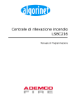
SIM1,2(6)
ZTB216-1,2
(1)
NTB216-1
(2)
OPT
(8)
SIM1,2(7)
FWI
2-1
(5)
FM1
(4)
FM2
(4)
ABB
216-1
(3)
OPT
(8)
OPT
(8)
OPT
(8)
LAB48-1
(9)
Battery
Battery
Case Series BC216
Battery
(1) Central processing board ZTB216-1 (BC216-1)
or ZTB216-2 (BC216-2, BC216-3)
(2) Power unit NTB216-1
(3) Display and operating board ABB216-1
(only with BC216-1 and BC216-2)
(4) Function modules GIF8-1 or LIF64-1
(5) Fire brigade interface FWI2-1 and FWZ2-1
(6) Serial interface modules SIM216-1 oder SIM216-2
(7) SIM216-1 or SIM216-2 (BC216-1)
or NIF5-1 (BC216-2, BC216-3)
(8) Optional space for RL58-1, RL58-2, SLM1-2, SZ58-2
(9) LED-display field LAB48-1
(not with BC216-3)
Battery
Auxiliary case
Figure 1:
2.2
Expansion versions of the fire detection control panel Series BC216
With the BCnet sectional control panels of the network control panel BCnet216 the network interface
NIF5-1 is basically implemented in the optional space (7), the only vacant serial interface left is
therefore optional space (6).
The display and operating board ABB216-1 and the optional LED-display board LAB48-1 are attached to the detachable case cover.
Components of the basic version
Which components are included in the corresponding basic version of the fire detection control panel
Series BC216 is described in detail from page 8 in Chapter 1.4: "Scope of delivery".
2.2.1
Case
The two-part powder-coated steel sheet case is intended for wall surface mounting. The cover can be
hooked into the bottom part of the case during commissioning with the cable to the central processing
board ZTB216-1 or ZTB216-2 plugged in. Two stand-by batteries with 12V/max. 20Ah each can be installed in the case even with fully extended control panel.
HB216BE.SAM / 0140 / AN9161206
ZN5015/59/9
10
2.2.2
Chapter 2 • Components of the fire detection control panel Series BC216
User Manual Series BC216 / Part B
Central processing board ZTB216-1, ZTB216-2
With its powerful 32-bit processor system, the central processing board ZTB216-1 or ZTB216-2, respectively in the applicable country-specific version is largely responsible for internal signal processing, communication with the display and operating board, the monitoring of the detector modules, the
monitoring of in- and outputs, the activation of the outputs and the communication with the peripheral
devices (e.g., signalling devices) of the system. With the help of optional interface modules, two serial
interfaces permit the connection of an external printer, the link-up to a remote maintenance system, a
connection to master systems (e.g., main panel, building management system) or with BCnet sectional
control panels of a network control panel BCnet216, the connection to the GSSnet.
Upon failure of the processor system of the central computer, the processor system of the display and
operating board takes on essential tasks of the central computer. In this way it is ensured that the lightemitting diode signals, the displays and the operation facilities required in the state of alarm are also
serviced upon failure of the central computer. Furthermore the relay HM1 on the fire brigade interface
FWI2-1 (usually used as primary transmitting device for fire alarms) as well as the supervised siren
output of the power unit NTB216-1 (usually used as primary alarming device) are activated in this
case.
The componentries of the fire detection control panel Series BC216 are connected with the central
processing board through a processor-supported bus system. In order to increase the failsafe capacity,
this bus system is further protected by an additional diverse bus system.
2.2.3
Power unit NTB216-1
The power unit NTB216-1 serves to generate the voltages for the supply of the fire detection control
panel, charging of the stand-by batteries, the supply of the automatic fire detectors and of the additional
devices connected internally and externally to the control panel from the mains voltage.
In addition to this, the standard outputs for summary alarm and summary fault, the supervised siren
output, the INFO bus connection and 16 open collector outputs with free to set parameters are arranged
on the power unit.
The power supply unit is designed as a primary switch converter with high efficiency, resulting in low
self-heating and consequently in a high MTBF value. A power failure will be recognised after a few
seconds and shown as a fault.
The automatic monitoring of the connected stand-by batteries (including their supply cables and the
fuse Si2) is accomplished through a periodical disconnection of the batteries from the charging device,
simultaneous loading with a load resistor and measuring of the battery voltage under that load. This
complex process ensures that - contrary to other simple monitoring methods - the supply voltage of the
entire fire detection system is not subject to periodic fluctuations, but remains largely constant.
Battery monitoring is not performed for as long as mains failure is being signalled.
Monitoring of the mains voltage or the stand-by batteries can be suppressed through parameter setup
for special cases where either no mains voltage or no stand-by batteries are available (see User
Manual / Part C).
81*
=8/$66
A fire detection system must be supplied by two independent power sources.
The stand-by batteries are charged with current limitation and temperature optimisation. The temperature sensor for controlling the final charge voltage is arranged on the right next to the terminal 20 of the
NTB216-1. If the stand-by batteries are not placed in the case of the control panel (or not immediately
next to the control panel), but at another place of installation with considerably different temperature
conditions, an external temperature sensor may be connected in place of the internal temperature
sensor.
HB216BE.SAM / 0140 / AN9161206
ZN5015/59/10
User Manual Series BC216 / Part B
Chapter 2 • Components of the fire detection control panel Series BC216
11
An electronic switching device disconnects the stand-by batteries from the charging device in the
events of short-circuit or overload, preventing repercussions for the control panel or the BCnet sectional control panel. The stand-by batteries are disconnected from the control panel also when there is a
risk of total discharge of the battery.
For reasons of safety a totally discharged stand-by battery is no longer charged automatically by the
charging device. The connections for the external devices and those within the control panel are fuseprotected separately, fuse failure is recognised immediately and displayed as a fault.
The entire installation connected to this control panel or BCnet sectional control panel is subject to
earth leakage monitoring by the power unit NTB216-1. If earth leakage occurs anywhere within the fire
alarm cable system, this is indicated on the fire detection control panel as a fault/earth leakage.
The earth leakage monitoring can be taken out of service through parameter setup for special cases
where a connection of the cable network with earth has been established on purpose (e.g., in an intrinsically safe area by the connection of a cable section with the local equipotential busbar) (see User
Manual / Part C).
81*
=8/$66
2.2.4
Since the fire detection control panel Series BC216 indicates any malfunction of the system, which
may be caused by multiple earth leakage, as a fault of that function, indication of simple earth leakage
is not required by the European Standard EN54.
Display and operating board ABB216-1
The display and operating board ABB216-1 has its own processor system to activate the LC-display
and light-emitting diodes and to enable the operation of the fire detection control panel. An alarm or
fault is acoustically signalled by the buzzer arranged on the display and operating board.
Upon failure of the display and operating board processor, the processor of the central processing
board ensures that the LED displays required in the state of alarm are activated and the operation of
the built-in buzzer and the supervised siren output of the NTB216-1 is maintained.
2.2.5
Mounting bracket BW216-1
A standardly built-in componentry mounting bracket, equipped with holes according to the LST standard grid, permits the installation of additional componentries. Relay modules RL58-1 or RL58-2, control zone modules SLM1-2, siren supervising modules SZ58-2, isolator modules and other
componentries for instance can be quickly and easily installed in this way.
2.3
Function modules for detectors and modules
Function modules for conventional detector technology and for intelligent ADM- or ADMPROtechnology are provided for the connection of fire detectors, fault detectors, technical detectors, control
modules and monitor modules. Installation space in the central processing board is provided for two of
these function modules. Depending on the size of the system, the control panel or the BCnet sectional
control panel can be equipped either with only one, two identical or two different function modules.
2.3.1
Conventional detector interface GIF8-1
The conventional detector interface GIF8-1 is employed for the connection of conventional detectors.
Up to 8 detector lines, each comprising one detector zone in addressable conventional technology, can
be connected to this module. Depending on your requirements, one or two conventional detector interfaces can be installed in the function module locations of the central processing board (ST2 or ST3, see
from page 20 in Chapter 3.3.1: "Conventional detector interface GIF8-1, Loop interface LIF64-1") and
thereby up to 16 detector lines can be connected.
Detector line is the term used for the (usually branched) cable path connecting the detectors with the
control panel. A detector zone is formed by the detectors of a surveilled area sharing a common display on the fire detection control panel. With the conventional detector interface GIF8-1, all detectors
connected to a detector line form one detector zone.
HB216BE.SAM / 0140 / AN9161206
ZN5015/59/11
12
2.3.2
Chapter 2 • Components of the fire detection control panel Series BC216
User Manual Series BC216 / Part B
Loop interface LIF64-1
The loop interface LIF64-1 is employed for the use of the intelligent analogue technology. A loop with
bi-directional data traffic for the connection of detectors and modules of ADM- or ADMPROtechnology can be connected to it. The detectors and modules connected to a loop can be combined
into a total of 128 independent zones.
Due to organizational reasons the total number of zones serviced by the fire detection control panel
BC216-1 or by each BCnet sectional control panel of the fire detection control panel BCnet216 must
not exceed 144.
Depending on your requirements, you can install one or two loop interfaces at the space for function
modules provided in the central processing board (plug-in port ST2 or ST3, see from page 20 in Chapter 3.3.1: "Conventional detector interface GIF8-1, Loop interface LIF64-1"), accomplishing up to 144
detector or actuation zones in this way.
During the configuration, the installer determines through parameter setup of each loop interface
whether ADM-technology (99 detectors + 99 modules per loop) or ADMPRO-technology (126 address points per loop) are to be processed.
2.4
Connection of fire brigade devices
The fire brigade interface FWI2-1 is available for the connection to a designated alarm respondent
(e.g., the fire brigade).
Two relays (HM1 and HM2) with free to set parameters and dry change-over contacts for passing
on alarms in various combinations,
9 inputs with free to set parameters,
8 outputs with free to set parameters, and
1 output for system fault
are arranged on this interface for the connection of a country-specific fire brigade control unit, a key
safe or a key depot adapter and other equipment. Individual functions can also be assigned to the inputs
or outputs with free to set parameters (see User Manual / Part C).
The fire brigade interface additional board FWZ2-1 that fits onto the fire brigade interface FWI2-1 is
provided for the line-monitored connection of a transmitting device. With this addition it is possible to
accomplish two independent outputs for transmitting devices (e.g., for alarm and/or fault signals)
which are monitored for interruption and short circuit. The line monitoring current of these outputs can
be parameterised.
Basically, a fire brigade interface FWI2-1 and a fire brigade interface additional board FWZ2-1 can be
built into every BCnet sectional control panel with the network fire detection control panel BCnet216.
Either further in- and outputs for general use (e.g., for actuations) are provided for the control panel or,
with main- and sub-control panel configuration, additional sectional fire brigade control units, sectional
key safes, etc. can be controlled.
With the fire detection control panel BC216-1 or the BCnet sectional control panel BC216-2, in case
of a failure of the processor system of the ZTB216-1 or ZTB216-2, the siren output of the power unit
NTB216-1 and its connected local devices as well as the relay HM1 (which is usually used as primary
transmitting device) on the fire brigade interface FWI2-1 are activated in the event of an alarm. As an
option it is additionally possible to activate the relay HM2 and the FWI-OC-output terminal 14 (see
from page 38 in Chapter 4.6.1: "Relay contacts on the FWI2-1" and from page 38 in Chapter 4.6.2:
"Open collector outputs of the FWI2-1"). A failure of the processor system of the ZTB216-2 of a nonoperatable BCnet sectional control panel BC216-3 ("black box control panel") is displayed as fault in
the overall system. Nevertheless, the local signalling devices and transmitting devices are not serviced
in case of alarm.
HB216BE.SAM / 0140 / AN9161206
ZN5015/59/12
User Manual Series BC216 / Part B
2.5
Chapter 2 • Components of the fire detection control panel Series BC216
13
Serial interface modules SIM216-1 and SIM216-2
The fire detection control panel BC216-1 can be expanded with two, every BCnet sectional control
panel of the network fire detection control panel BCnet216 can be expanded with one serial interface
of type RS232-C. The serial interface modules SIM216-1 and SIM216-2 serve to convert the processor
signals to the standardised interface levels.
The serial interface module SIM216-1 is designed with isolated potentials and is therefore suitable for
the connection of devices, which are not themselves designed with isolated potentials. Typical applications for this are: Printers, PC with parameter setup software PARSOFT-1 or -2x, etc.
The serial interface module SIM216-2 has no potential separation and is therefore suitable only for the
connection of a device having its own internal potential separation. This interface module also supports
handshake lines of the interface. Typical applications for this are: Remote maintenance via modem, remote parameter setup via modem, etc.
2.6
Network interface NIF5-1
The connection of the BCnet sectional control panels of a network fire detection control panel
BCnet216 to the redundant data line which combines the BCnet sectional control panels to an overall
control panel is constructed in serial technology via the network interface NIF5-1 which is plugged
onto the central processing board ZTB216-2. Besides converting the processor signals to the RS485 interface level of the GSSnet, this componentry also realizes error management for faults of the circularly
constructed GSSnet data line via intelligent short circuit isolators and interface change-over switches.
2.7
Light-emitting diode displays
The optionally applicable LED-display field LAB48-1 contains 48 freely adjustable light-emitting diode pairs (one red and one yellow light-emitting diode each) to indicate the activation, fault or switchoff conditions of a defined part of the system. The LED-display field LAB48-1 is controlled by the display and operating board ABB216-1. Insertable labels serve to individually name the light-emitting
diodes.
2.8
Stand-by battery
The case of the fire detection control panel Series BC216 is designed to accommodate 2 seriesconnected stand-by batteries of 12V/17Ah (max. 20Ah). If the capacity of the built-in batteries is not
sufficient, the capacity can be doubled by parallel-connecting another 17Ah arrangement (see from
page 15 in Chapter 2.9: "Auxiliary case GEH216-4" and from page 29 in Chapter 4.2.1: "Connection of
mains power, the stand-by battery and the external devices"). These additional batteries should be installed as close as possible to the built-in batteries in order to ensure identical temperature conditions
for all batteries.
Stand-by battery charging is automatically adapted by the control panel to the operating temperature of
the batteries.
81*
=8/$66
Only 24V units (i.e., 2 series-connected individual 12V-batteries) may be connected in parallel. The
individual batteries must be of the same type.
In order to meet the requirements of the 24-hour charging time, the total capacity of the stand-by batteries connected to the BC216-1 or to a BCnet sectional control panel of a BCnet216 must not exceed
34Ah (e.g., 2 x 17Ah connected in parallel).
Use the auxiliary case GEH216-4 which fits to the fire detection control panel Series BC216 for installing additional stand-by batteries or other additional elements, see from page 15 in Chapter 2.9:
"Auxiliary case GEH216-4".
The stand-by batteries can generally be operated in any position, but the upright position is preferred
(with the connections facing up). Ensure that the connections of the batteries do not make electrical
HB216BE.SAM / 0140 / AN9161206
ZN5015/59/13
14
Chapter 2 • Components of the fire detection control panel Series BC216
User Manual Series BC216 / Part B
contact with the case or other metallic parts during the installation or during subsequent operation, this
might destroy the battery or the fire detection control panel!
Connect the connection lines to the stand-by battery only when all the cabling work on the system has
been completed and checked!
Use only maintenance-free, sealed stand-by batteries with fixed electrolyte and low self-discharge,
which are specially suited and approved for emergency power supply of electronic security systems in
standby parallel mode.
Do not under any circumstances use batteries of a type other than the type provided as standard, which has been specially designed for use in security systems! The charging process employed in the fire detection control panel is designed for this type of battery, other batteries
could start leaking in operation or even burst - the fire detection control panel could be
destroyed!
2.8.1
Determining the required capacity of the stand-by battery
In general the required stand-by battery capacity is dependent on
the system current during the mains failure,
the system current during acoustic and optical alarm and
on the required mains failure bridging time.
A separate stand-by battery is installed in every BCnet sectional control panel of the network fire detection control panel BCnet216. The required capacity of these batteries is to be harmonized with the
system parts connected to the corresponding BCnet sectional control panel.
The system current to be supplied by the stand-by battery upon mains failure must be calculated during
the project phase. To do so, take the quiescent current values from the data sheets of the devices you
intend using in the system. The values of the control panel itself can be found from page 55 in Chapter
6: "Specifications". Please note that the fire detection control panel will be subject to a fault status in
the event of mains failure!
Avoid all loads not absolutely necessary for the operation of the system. Any permanently connected
device will be a burden on the stand-by battery upon mains failure. As part of commissioning the entire system, check in the state of mains shut down to see if the measured system current corresponds
with the calculated value.
Determine the current consumption in the state of alarm from the data sheets of the acoustic alarming
devices (sirens) and the optical alarming devices (flashlight) employed. Take into account also the
power consumption of connected transmitting devices and other facilities (e.g., a fire brigade key safe
or a fire brigade key depot).
The required mains failure bridging time is dependent on the respective installation regulations and the
local conditions.
81*
=8/$66
A typical requirement, e.g., is that a fire detection system must be able to recognise an alarm even
72 hours after the mains failure started and to signal such alarm optically and acoustically for 30
minutes.
Without taking into account reserves, efficiency, etc., you can approximately determine the minimum
capacity of the required stand-by batteries, using the above mentioned installation regulations as a base
as follows
CMIN = 72 × IMAINS FAILURE + 0.5 × IAL whereas
CMIN
... Minimum capacity in [Ah]
IMAINS FAILURE ... total system current during mains failure in [A], without raising alarm
IAL
... entire system current while raising the alarm in [A]
HB216BE.SAM / 0140 / AN9161206
ZN5015/59/14
User Manual Series BC216 / Part B
Chapter 2 • Components of the fire detection control panel Series BC216
15
With a BCnet sectional control panel of the network fire detection control panel BCnet216 the current
required for supplying the system section which is serviced by the corresponding BCnet sectional control panel (including the BCnet sectional control panel itself) is referred to as "system current".
Add a safety allowance to this calculated minimum value to compensate for exemplary fluctuations or
capacity losses caused by the effect of temperature and ageing.
2.9
Auxiliary case GEH216-4
The auxiliary case GEH216-4 with the same dimensions as the control panel case is available for the
installation of additional stand-by batteries if higher current is required by the fire detection system or
when optional assemblies are installed.
The auxiliary case can house either
four batteries 12V/17Ah (one battery bracket BK216-1 is required additionally) and a mounting
bracket BW216-1 or
two batteries 12V/17Ah (a maximum of 20Ah each) and four mounting brackets BW216-1.
2.10
Battery bracket BK216-1
An auxiliary case GEH216-4 can house up to four stand-by batteries of 12V/max. 20Ah. Two stand-by
batteries are arranged on the bottom of the auxiliary case, further two batteries can be installed by using the battery bracket BK216-1 which is screwed on to the bottom part of the case.
2.11
Mounting bracket BW216-1
Mounting brackets BW216-1 are used for the installation of additional componentries fitting the LST
standard grid by using plastic spacers.
2.12
Printer
A printer can be connected to the fire detection control panel BC216-1 or to every BCnet sectional control panel of the network control panel BCnet216 either permanently or only for service purposes via
one of the two serial interfaces. The printer can also be installed separately from the control panel
while the cable length is limited to 5m.
The control panel is prepared for the connection of the following types of printer:
Seiko DPU-414, Art. Nr. 227003
Upright unit with particularly small dimensions (160mm × 170mm × 66.5mm)
Thermal paper, 28m/roll, automatic change-over to offline mode on paper end
80 characters per line
Operation via power supply unit and optional Ni-Cd battery
Required printer cable: Port D-SUB 9-pin, plug D-SUB 9-pin, max. length 5m
Epson LX-300, Art. Nr. 227008
Upright unit with the dimensions 366mm × 275mm × 132mm
Matrix printer, 9 needles
Standard reel paper
80 characters per line
Mains operation
Required printer cable: Port D-SUB 9-pin, plug D-SUB 25-pin, max. length 5m
Both types of printer require the installation of a serial interface module SIM216-1 in the control panel.
2.12.1
Operation as event printer
The events are recorded with date and time, a continuous number and the additional text information
(e.g., location) as a function of the set printer filter (see User Manual / Part C).
HB216BE.SAM / 0140 / AN9161206
ZN5015/59/15
16
2.12.2
Chapter 2 • Components of the fire detection control panel Series BC216
User Manual Series BC216 / Part B
Operation as service printer
This operation type of the printer was installed especially for supporting the service and maintenance
technician. As installer you can select from the following print-out possibilities for the connected and
set-up printer (see User Manual Series BC216 / Part A, menu point [System] - [Print-out]):
Service print-out: On request the printer prints the contents of the event memory, considering the
set printer filter.
Settings print-out: On request the printer prints a summary of the entire control panel configuration (hardware and parameter setup).
Measured value print-out: The printer prints the measured values of the connected ADM or
ADMPRO detectors and modules. The measured value print-out is available as an unique status
print-out of one or several elements (e.g., all detectors of one zone) or as an automatically and continuously operating current measuring value output for a single element.
2.13
Accessories
2.13.1
Printer cable
Standard cables obtainable in specialized stores are used as connection cables for the optional printers
Seiko DPU-414 and Epson LX-300 for connection to the serial interface module SIM216-1. The structure of these cables is shown in the following figures.
SIM216-1
socket
D-SUB 9 pin
Figure 2:
2.13.2
length max. 5m
2 TxD
3 RxD
5 GND
8 CTS
Seiko DPU-414
connector
D-SUB 9 pin
Printer cable for Seiko DPU-414 (Art. Nr. 227007, length: 1,8m)
SIM216-1
socket
D-SUB 9 pin
Figure 3:
RxD 2
TxD 3
GND 5
CTS 8
RxD 2
TxD 3
GND 5
CTS 8
length max. 5m
2 TxD
Epson LX-300
3 RxD
7 GND connector
20 DTR D-SUB 25 pin
Printer cable for Epson LX-300
Connection cable between BC216-1, -2, -3 and a PC
In order to connect a PC (Notebook) to the fire detection control panel BC216-1 or to a BCnet sectional
control panel BC216-2 or BC216-3 you require a standard cable obtainable in specialized stores. The
structure of the cable is shown in the following figure.
SIM216-1
socket
D-SUB 9 pin
RxD 2
TxD 3
GND 5
length max. 3m
3 TxD
2 RxD
5 GND
PC
socket
D-SUB 9 pin
In each of the two D-SUB ports it is necessary to additionally connect the ports 1 with 4 and 7 with 8.
Figure 4:
Connection cable control panel - PC
HB216BE.SAM / 0140 / AN9161206
ZN5015/59/16
User Manual Series BC216 / Part B
3
Chapter 3 • Assembly and installation of optional componentries
17
Assembly and installation of optional componentries
This chapter presents the assembly of the fire detection control panel BC216-1, the BCnet sectional
control panels of the fire detection control panel BCnet216 and the auxiliary case GEH216-4 as well as
the installation of the optional componentries and facilities. You can install and wire-up the optional
componentries beforehand so that you merely have to assemble and connect the already assembled control panel on site. Parameter setup (see User Manual / Part C) can be carried out beforehand also, except for date and time the input data will be preserved indefinitely even without supply voltage.
Do not under any circumstances transport the fire detection control panel or the auxiliary case
with the stand-by batteries installed! It is indispensable to remove the batteries from the case for
transporting (even over short distances!).
Attention with MOS components! The MOS components employed in the device can be destroyed
by static loads with the device opened. Prior to and during the work carried out on the printed circuit
boards it is necessary to reliably discharge static charges of the body by contacting an earth-connected
metallic part (e.g., the earth-connected control panel case).
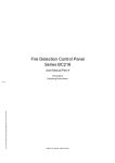
Figure 5:
3.1
Opened case of the fire detection control panel BC216-1
A ... Connection cable from the display and operating board ABB216-1
to the central processing board ZTB216-1 / connector ST1
B ... FASTON Tabs for the earth connection of the case cover
C ... Mounting bracket for optional componentries
D ... Equipotential busbar connection
E ... Terminal connections for shielding wires of shielded cables
Place of assembly
The fire detection control panel BC216-1 and every BCnet sectional control panel of the network fire
detection control panel BCnet216 must be installed in a clean and dry room on a stable wall surface.
The room temperature must range between -5°C and +50°C, the relative humidity of the air must not
exceed 90%. Protect the control panel against splashing water and other mechanical and chemical
effects.
The place of assembly must be easily accessible for the public safety personnel (e.g., the fire brigade).
Coordinate the place of assembly with the officials concerned. The control panel must be installed at a
level above ground at which operation and reading of the displays is possible without obstacle.
81*
=8/$66
HB216BE.SAM / 0140 / AN9161206
ZN5015/59/17
The fire development risk must be low in the room where the fire detection control panel is to be
mounted. The room must be monitored by the fire detection system.
18
3.2
Chapter 3 • Assembly and installation of optional componentries
User Manual Series BC216 / Part B
Panel installation
The control panel is installed in a 2-piece powder-coated steel sheet case (consisting of the bottom part
and the cover). The cover is detachable and can be hooked into the bottom part with the connection cable plugged in to facilitate commissioning. All necessary mounting elements (bolts and plugs) are included in the package accompanying the control panel.
C
B
A
Figure 6:
Control panel case
A ... dimensions of the control panel case, position of the installation bores
B ... swivel area of the case cover (approximate values)
C ... case cover hooked into the bottom part of the case
At least 25mm of vacant space must be available below the case to remove the case cover from the
bottom part! This minimum vacant space is sufficient for removing the case cover but not for tilting,
corresponding to figures 6B or 6C.
Loosen the two mounting screws of the case cover and tilt the cover forward. Disconnect the flat cable connecting the display and operating board with the central processing board ZTB216-1 or
ZTB216-2 from the central processing board. Loosen the two earth connections from the case and
remove the case cover.
Mark the three mounting points on the wall, drill the mounting holes with a drill suitable for the
plugs, insert the plugs in the drilled holes and provisionally screw the mounting screws in the two
upper plugs.
Suspend the control panel from the two screws screwed into the wall. Pull the already installed cables through the cable openings at the back of the case, ensuring the proper separation of cables carrying mains voltage and low-voltage.
Secure the case using the lower mounting screw. Then tighten the two upper screws, adjusting irregular mounting surfaces through the insertion of spacer elements if required. Ensure that no cables
are squashed and that the case is not bent by an uneven mounting surface during tightening.
Install the optional componentries at the places provided for this purpose, see from page 19 in Chapter 3.3: "Installation of optional components".
Carry out all cabling jobs according to your installation documentation taking into account the connection diagrams shown from page 28 in Chapter 4: "Connection" and the installation regulations
for fire alarm systems. Ensure that mains power is not switched on while cabling jobs are in
progress!
When using shielded cables, connect the shielding wires with the case (earth). The terminal connections on the case bottom part below the function modules are provided for this purpose. Bare shielding wires must be insulated by fitting an insulation tube or similar measures to prevent short
circuits.
HB216BE.SAM / 0140 / AN9161206
ZN5015/59/18
User Manual Series BC216 / Part B
Chapter 3 • Assembly and installation of optional componentries
19
The fire detection control panel Series BC216 is comprehensively protected against the effects of electrical faults. Shielded cables are therefore not required for the safe operation of the control panel under
normal ambient conditions.
Hook in the case cover and reconnect the flat cable to the connector ST1 of the central processing
board ZTB216-1 or ZTB216-2 (see survey figure from page 19 in Chapter 3.3: "Installation of optional components") and the two earth connections.
When closing the case ensure that the bottom part of the case is introduced in the lateral guides of
the case cover and no cable is squashed. Secure the case cover with the two mounting screws provided for this purpose.
It is indispensable for the case of the control panel to be earthed in operation! For this purpose connect
the control panel case with the equipotential busbar connection of the local electrical installation. Ensure that protective earth is connected to the earth connection terminal on the bottom part of the case,
the connection between the protective earth connection of the mains terminal and the bottom part of
the case is established and the case cover and the bottom part of the case are electrically connected
with the two earth connection lines.
3.3
Installation of optional components
All installation work must only be carried out with the fire detection control panel in the de-energised
state. Mains power must be switched off and locked to prevent switching on and the stand-by batteries
must be disconnected.
It is absolutely essential that the protective earth conductor and the equipotential busbar are connected
to the bottom part of the case to ensure the required discharge of electrostatic charges.
All optional modules are delivered in an antistatic package. Before removing a module from the package it is essential that you discharge yourself by contacting an earth-connected metallic part (e.g., the
control panel case). Plug the componentry taken from the package in the connector of the control panel
provided for this purpose and tighten the screws. If you remove a componentry it must be immediately
placed in the antistatic package without storing the module anywhere in between.
Figure 7:
HB216BE.SAM / 0140 / AN9161206
ZN5015/59/19
Survey of the connection of optional componentries to the central processing board ZTB216-1 or
ZTB216-2.
A ... Place of installation for fire brigade interface FWI2-1
B ... Place of installation for function module FM1
C ...Place of installation for function module FM2
D ...Connector ST5: Power unit NTB216-1
E ... Connector ST4: Fire brigade interface FWI2-1
F ... Connector ST2: Function module FM1
G ...Connector ST3: Function module FM2
H ...Connector ST1: Display and operating board ABB216-1
I ... Connector ST8: Connector for PC keyboard
J ... Connector ST6: "Serial interface 1" serial interface module SIM216-1 or SIM216-2
K ...Connector ST7: "Serial interface 2"
20
Chapter 3 • Assembly and installation of optional componentries
User Manual Series BC216 / Part B
BC216-1: serial interface module SIM216-1 or SIM216-2
BCnet sectional control panel of a BCnet216: NIF5-1
L ... Connector ST9: 10-pin connector for diagnostic functions during the manufacturing process
3.3.1
Conventional detector interface GIF8-1, Loop interface LIF64-1
Ensure that the control panel is de-energised. Reliably discharge static loads also during the following
activities by touching the control panel case connected to the protective conductor.
Plug the first conventional detector or loop interface in the function module space 1 (ST2) of the
central processing board ZTB216-1 or ZTB216-2 and secure the module to the case bottom part using the two enclosed screws.
Plug the second conventional detector or loop interface (if required) into the function module space
2 (ST3) of the central processing board and secure it to the case bottom part with the two enclosed
screws.
With a BCnet sectional control panel of a fire detection control panel BCnet216 the mounting bolts
of the function module space 2 are additionally used for securing the terminal board of the network
interface NIF5-1. In this case you have to remove the two hexagon bolts which secure the terminal
board and plug the corresponding function module (GIF8-1, LIF64-1) in the central processing
board as priorly described; secure the function module by tightening the hexagon bolts. Successively, secure the terminal board of the NIF5-1 on these bolts by using the screws enclosed with
every function module (further hints see from page 24 in Chapter 3.3.6: "Network interface
NIF5-1").
Ensure that the conventional detector or loop interfaces are plugged in only in the function module
spaces provided for this purpose (ST2 or ST3).
To ensure a safe earth connection the mounting screws must be adequately tightened.
3.3.2
Fire brigade interface FWI2-1
Verify that the control panel is de-energised. Reliably discharge static loads also during the following
activities by touching the control panel case connected to the protective conductor.
Plug the fire brigade interface FWI2-1 into the plug-in space 4 (ST4) of the central processing board
ZTB216-1 or ZTB216-2 and secure the assembly to the case bottom part with the two enclosed
screws.
Ensure that the fire brigade interface is only plugged into the intended plug-in space ST4.
The mounting screws must be sufficiently tightened to ensure safe earth connection.
If you require monitored outputs for transmitting devices, the fire brigade interface additional board
FWZ2-1 must be fitted to the FWI2-1 before installing the fire brigade interface in the control panel.
3.3.3
Fire brigade interface additional board FWZ2-1
Install the fire brigade interface additional board on the fire brigade interface with the help of the three
enclosed hexagon bolts as shown in the following.
HB216BE.SAM / 0140 / AN9161206
ZN5015/59/20
User Manual Series BC216 / Part B
Figure 8:
Chapter 3 • Assembly and installation of optional componentries
21
Assembly of the fire brigade interface additional board FWZ2-1 to the fire brigade interface FWI2-1.
The power unit NTB216-1 positioned in front was removed for more detailed photographic presentation.
A ... Enclosed hexagon bolts
Ensure that the control panel is de-energised. Reliably discharged static loads also during the following
activities by touching the control panel case connected to the protective conductor.
If the fire brigade interface FWI2-1 is already installed in the control panel, it has to be removed.
Attach one of the supplied hexagon bolts to the fire brigade interface in the centre bore below the
pin terminal ST2 by means of the enclosed nut.
Plug the fire brigade interface FWI2-1 into the plug-in space 4 (ST4) of the central processing board
ZTB216-1 or ZTB216-2 and secure it to the case bottom part using the remaining two hexagon
bolts.
Plug the fire brigade interface additional board FWZ2-1 into the pin terminal ST2 of the fire brigade
interface FWI2-1 provided for this purpose. Ensure that all 16 pins of the pin terminal are engaged
in the connector and are not bent. When plugging in, support the fire brigade interface FWI2-1 from
behind to avoid excessive mechanical load on the plug connection ST4.
Secure the fire brigade interface additional board to the hexagon bolts using the three enclosed recessed head screws.
To ensure secure earth connection, adequately tighten the hexagon bolts and the mounting screws.
3.3.4
LED-display field LAB48-1
The LED-display field consists of two printed circuit boards, which are interconnected when delivered.
These two printed circuit boards must be separated prior to installation. To do so, position the unit
against a solid edge along the provided scored fracture line and break the unit over this edge using both
hands. Ensure that the connection cable connecting the two printed circuit boards and the components
mounted on the printed circuit boards are not damaged.
Prior to and during the work to be conducted on the printed circuit boards, static charges of the body
must be reliably discharged by contacting an earthed metallic part.
Slide the enclosed plastic spacer tubes onto the 6 threaded pins in the interior of the case cover, fit each
of the printed circuit boards onto 3 of the threaded pins and secure the printed circuit boards to the
threaded pins using the enclosed nuts according to the following figure. Connect the flat cable to the
connector ST2 of the display and operating board ABB216-1.
HB216BE.SAM / 0140 / AN9161206
ZN5015/59/21
22
Chapter 3 • Assembly and installation of optional componentries
Figure 9:
User Manual Series BC216 / Part B
Installation of the LED-display field LAB48-1 in the cover of the fire detection control panel Series
BC216.
Spacer tubes (not visible in the picture) are fitted onto the threaded pins between the printed circuit
boards and the cover.
A ... Slots for accommodating insertable labels
B ... Connector ST2
Installation of the LED-display field LAB48-1 in a non-operatable BCnet sectional control panel
(BC216-3) of a network fire detection control panel BCnet216 is not possible.
3.3.4.1
Insertable labels for LED-display field
When delivered, two insertable labels are affixed to the interior of the control panel. Depending on the
side with which they are inserted, the insertable labels fulfil two purposes:
If no LED-display field is used, the insertable labels are introduced with the evenly grey side in
front. They cover both the transparent inscription field and also the transparent light-emitting diode
passages.
If the LED-display field is employed, the inscribed insertable labels are introduced with the
grey/transparent side first.
Inscribe the insertable labels with suitable means, taking into account the position of the inscription to
the lateral reference marks (see following figure). The inscription must be positioned to the right of the
transparent part of the label! Subsequently slide the label behind the transparent field next to the lightemitting diodes from below, locate the label with adhesive tape and cut the excessive length with a pair
of scissors.
Figure 10: Inscription label for LED-display field LAB48-1
The inscription must be positioned to the right of the transparent part of the label. The reference
marks (A) symbolise the lines, the inscription should be positioned central between two such lines.
HB216BE.SAM / 0140 / AN9161206
ZN5015/59/22
User Manual Series BC216 / Part B
Chapter 3 • Assembly and installation of optional componentries
23
You can also use a cardboard or paper label, which you previously printed with a laser printer instead
of the plastic strip. Print examples for such insertable labels for use with some standard programmes
can be found on the CD on which the parameter setup software PARSOFT-1 is delivered (file names:
LEDBeschrift.wk4, LEDBeschrift.123, LEDBeschrift.xls). Ensure that the inserted strip does not
cover the light-emitting diodes.
On no account should you use sharp or pointed tools to pull out an inserted strip. The surface of the
keypad is highly sensitive to scratching on the inside and these scratches are also visible from the
outside.
3.3.5
Serial interface modules
By using the enclosed hexagon bolts, install the serial interface modules SIM216-1 and SIM216-2 on
the central processing board ZTB216-1 on the plug-in spaces ST6 or ST7 or on plug-in space ST6
when using the central processing board ZTB216-2 of a BCnet sectional control panel. Depending on
the pin terminals to which you connect the interface module, the interface module will be addressed as
"Serial interface 1" (ST6) or as "Serial interface 2" (ST7) during parameter setup.
With all BCnet sectional control panels of the fire detection control panel BCnet216, plug-in space
ST7 of the central processing board ZTB216-2 is reserved for the connection to the GSSnet via the
network interface NIF5-1.
Figure 11: Arrangement of the serial interface modules SIM216-1 and SIM216-2 on the central processing
board ZTB216-1 of the fire detection control panel BC216-1. The two plug-in spaces ST6 and ST7 are
functionally identical.
A ... Plug-in space ST6, "Serial interface 1"
B ... Plug-in space ST7, "Serial interface 2"
Ensure that the control panel is de-energised. Reliably discharge static loads also during the following
activities by touching the control panel case connected to the protective conductor.
For the installation as "Serial interface 1" (plug-in space ST6), remove the two screws on the top
right of the central processing board and screw in the enclosed hexagon screws instead.
Plug the serial interface in the pin terminal ST6 of the central processing board provided for this
purpose. Ensure that all 16 pins of the pin terminal are introduced and not bent.
Take care that the componentries are plugged-in as shown in the above figure (figure 11). The connection is not secured against wrong polarity, a componentry connected invertedly can cause considerable
damage to the control panel.
Secure the serial interface module to the hexagon bolts using the two screws you removed
beforehand.
Under no circumstances connect a cable to a serial interface module unless the module is tightly
screwed to the central processing board.
The installation as "Serial interface 2" (plug-in space ST7) is admissible with the fire detection control panel BC216-1 only. It is carried out similarly to the installation on plug-in space ST6, but displaced by 180°: Remove the two screws from the right bottom of the central processing board and
replace with the enclosed hexagon bolts. The further procedure is the same as above.
HB216BE.SAM / 0140 / AN9161206
ZN5015/59/23
24
3.3.6
Chapter 3 • Assembly and installation of optional componentries
User Manual Series BC216 / Part B
Network interface NIF5-1
The network interface NIF5-1 is necessary for every BCnet sectional control panel of a fire detection
control panel BCnet216 for the connection to the network. With every BCnet sectional control panel it
is installed as standard on plug-in space ST7 of the central processing board ZTB216-2 at delivery.
Figure 12: Arrangement of the network interface NIF5-1 on the central processing board ZTB216-2 of a BCnet
sectional control panel (BC216-2 or BC216-3) of the fire detection control panel BCnet216.
A ... mounting screws of the ZTB216-2
B ... hexagon bolts of the enclosed packet of assembly material of the NIF5-1
When installing a network interface NIF5-1 supplementary, proceed as described in the following. Ensure that the control panel is de-energised. Reliably discharge static loads also during the following activities by touching the control panel case connected to the protective conductor.
Replace the two screws (A) on the right lower part of the central processing board with the enclosed
hexagon bolts (B).
Plug the network interface NIF5-1 in the pin terminal ST7 of the central processing board provided
for this purpose. Ensure that all 16 pins of the pin terminal are introduced and not bent.
Secure the network interface to the hexagon bolts using the two screws you removed beforehand.
The installation of the terminal board of the NIF5-1 is dependent on whether or not a function module is installed in installation space FM2 of the sectional control panel.
A function module is installed in installation space FM2:
Replace the two screws which secure the function module FM2 to the case bottom part with the enclosed hexagon bolts (B). Screw the terminal board of the network interface on the hexagon bolts of
the FM2 using the two screws you removed beforehand.
Installation space FM2 is vacant:
Secure the terminal board of the network interface to the mounting bolts of installation space FM2
using the two enclosed hexagon bolts.
3.3.7
Relay modules RL58-1 and RL58-2
A mounting bracket to accommodate up to four relay modules is provided in the fire detection control
panel. The modules are installed using the enclosed plastic spacers. Connection is by means of the flat
cables enclosed with the relay modules. The first relay module RL58-1 is plugged to the connector 1
(ST1), the second relay module RL58-1 to the connector 2 (ST2) of the power unit NTB216-1.
HB216BE.SAM / 0140 / AN9161206
ZN5015/59/24
User Manual Series BC216 / Part B
Chapter 3 • Assembly and installation of optional componentries
25
Figure 13: Installation of the relay modules RL58-1 in the standard mounting bracket and connection to the
plug-in spaces ST1 and ST2 of the power unit NTB216-1.
A ... Connector ST2
B ... Connector ST1
Proceed in like manner for connecting relay modules of type RL58-2 taking into account the cascading
possibility of two modules.
In addition to connecting with the flat cables, the relay modules must also be connected to the 24V
supply voltage (see page 33 in Chapter 4.2.5: "Connection of relay modules RL58-1 and RL58-2").
After a possible removal of the mounting bracket, the bracket must be reinstalled in the original position (with the short leg downward, see the above figure).
3.3.8
Stand-by batteries
Place the stand-by batteries in the bottom part of the fire detection control panel case or the auxiliary
case according to the following figure. Ensure that you do not short-circuit the battery terminals with
the overhead mounting bracket when installing the batteries.
Figure 14: Position of installed stand-by batteries in the bottom part of the case
Connect the stand-by batteries to the power unit only when all cabling work has been completed!
Install the stand-by batteries in the case only when it has been permanently and securely mounted to
the wall. The stand-by batteries are heavy, provisionally screwed in screws may be torn from the wall
by that weight!
Under no circumstances must a fire detection control panel Series BC216 be transported with
stand-by batteries installed!
HB216BE.SAM / 0140 / AN9161206
ZN5015/59/25
26
3.4
Chapter 3 • Assembly and installation of optional componentries
User Manual Series BC216 / Part B
Installation of the auxiliary case GEH216-4
The same instructions apply for the installation and the place of assembly of the auxiliary case
GEH216-4 as for the control panel (see from page 17 in Chapter 3.1: "Place of assembly" and from
page 18 in Chapter 3.2: "Panel installation"). Basically you should install the auxiliary case to the left
or to the right of the control panel case in direct vicinity. It is ensured only then that
the cables connecting the two cases are protected sufficiently against EMC and mechanical influences and
the temperature conditions inside the two cases are approximately equal.
81*
=8/$66
3.4.1
In order to refer to the two cases as "fire detection control panel", the control panel Series BC216 case
and the auxiliary case GEH216-4 must be installed directly to one another.
Installation of the stand-by batteries
The same instructions and hints apply for the installation of the stand-by batteries in the auxiliary case
GEH216-4 as for the installation in the control panel (see from page 25 in Chapter 3.3.8: "Stand-by
batteries").
If you intend to install more than one battery set (consisting of 2 batteries of 12V/17Ah, max. 20Ah) in
the auxiliary case GEH216-4 you have to install a battery bracket BK216-1, corresponding to the following figure. The assembly material necessary is enclosed to the battery bracket.
Figure 15: Auxiliary case GEH216-4 with installed battery bracket BK216-1
An auxiliary case GEH216-4 may under no circumstances be transported with stand-by batteries installed!
3.4.2
Installation of mounting brackets BW216-1
Thread bolts are arranged on the case bottom part to which up to 4 optional mounting brackets for additional componentries (mounting brackets BW216-1) can be installed, corresponding to the following
figure. The assembly material necessary is enclosed to every mounting bracket BW216-1.
Is a battery bracket already installed in the auxiliary case GEH216-4, only 1 mounting bracket
BW216-1 can be installed additionally.
HB216BE.SAM / 0140 / AN9161206
ZN5015/59/26
User Manual Series BC216 / Part B
Chapter 3 • Assembly and installation of optional componentries
Figure 16: Auxiliary case with installed mounting brackets BW216-1
HB216BE.SAM / 0140 / AN9161206
ZN5015/59/27
27
28
4
Chapter 4 • Connection
User Manual Series BC216 / Part B
Connection
This chapter generally describes the connection of the usual components of a fire detection system to
the fire detection control panel Series BC216. With the network fire detection control panel BCnet216
the connection hints are analogously valid for all BCnet sectional control panels.
Detailed connection and terminal assignment of detectors, signalling devices, transmitting devices, operating and display facilities, etc., are described in the respective equipment descriptions.
4.1
General instructions
The conductor cross section of the connection cables to the external components must be chosen as a
function of the power consumption of the connected components and the length of the cables. In dimensioning the wires, pay special attention to the voltage drops on the connection cables of the signalling devices! To ensure adequate strength, adhere to the minimum core diameter of 0.6mm for the
connection of external components.
If the number of connection terminals for the 24V supply of the external devices is inadequate, additional distribution terminals must be installed. On no account should several wires be connected to one
terminal.
The wires must be pull-relieved in the control panel. A stamped bracket in the cable inlet area to which
cables can be secured by means of cable straps serves this purpose.
If shielded cables are used for the installation, the shielding wires must be connected with the control
panel case on one side. Terminal connections are provided for this purpose in the control panel case
bottom part. The bare shielding wires must be insulated (e.g., by covering with an insulating tube) so
that they cannot cause any short circuits. The shielding wires of an interrupted wiring (e.g., with a detector base) must be safely connected to avoid earth leakage at this point. In order to avoid induction
loops, the shielding wire of one end of a circular wiring installation must only be connected to one of
the earth connections of the control panel case (e.g., only at the beginning of the ring line), and the
shielding wire of the other end of the ring line must be insulated.
Observe the installation regulations for fire alarm systems and the regulations for electrical installations! Connect the local equipotential connection carefully to the screw connection installed in the case
bottom part to ensure that the protective measures are fully effective.
If you have dislocated components of the control panel (e.g., relay modules, other switching devices,
batteries, etc.) to an auxiliary case, all protective measures (connection to protective earth, equipotential connection, etc.) must also be taken for the auxiliary case.
Ensure safe separation of the mains power wiring and the 24V low voltage lines.
Before starting any installation work, commissioning or maintenance, all actuation devices which may
automatically be activated by the fire detection control panel (e.g., extinguishing systems) must be reliably taken out of service. Unintended activation of actuations may endanger human life or result in
major damage to property. Establish contact with the responsible person (e.g., fire prevention officer,
safety representative) to have the necessary mechanical or electrical switch-offs carried out.
All additional materials required for the installation, connection and commissioning are included in the
package accompanying the fire detection control panel and the optional componentries. Keep the leftover material in the control panel case. This remaining material may come in handy for possible expansions or modifications.
Consider that with the network fire detection control panel BCnet216 the single GSSnet members are
not galvanically interconnected but are completely electrically isolated from each other!
The components of the EMC protection circuits of the inputs and outputs are not shown in the following connection diagrams to improve clarity.
HB216BE.SAM / 0140 / AN9161206
ZN5015/59/28
User Manual Series BC216 / Part B
4.2
Chapter 4 • Connection
29
Power unit NTB216-1
The power supply connections, the line-monitored connections of the siren output, the INFO bus connections, the open collector NTB auxiliary outputs and the relay outputs for alarm and fault are arranged on the power unit NTB216-1.
ST2
NTB auxiliarxy outputs 9-16
PE
Mains
N
L
ST1
NTB auxiliary outputs 1-8
Mains fuse
Si 1
0,5At
JP1
INFO bus
2mA/20mA
Si 3
D23
LED for
INFO bus
0,1 At
0,8 At
EXT2+3
Si 5 Si 4
0,8 At
Si 2
2,5 At
stand-by battery
yegn
INFO bus
EXT1
stand-by
battery
external
consumers
L-
L+
GND
+24V
GND
GND
+24V
GND
+EXT3
GND
+EXT2
+EXT1
+24V
GND
1 2 3 4 5 6 7 8 9 10 11 12 13 14 15 16 17 18 19 20
INFO bus
siren output
alarm
fault
contact contact
Figure 17: Position of connection elements and fuses on the power unit NTB216-1
4.2.1
Connection of mains power, the stand-by battery and the external devices
Perform the connection in accordance with the following connection diagram. Connect the
yellow/green protective earth conductor cable of the NTB216-1 to the FASTON Tab in the case bottom
part.
Do not connect the mains power or the stand-by battery to the NTB216-1 before the cabling of the entire system has been completed and carefully tested.
NTB216-1
2,5 At
1
Si2
Current limitation
1,8 A
PE
Mains
230V~/50Hz
N
0,8 Af
3
Si5
0,8 Af
0,5 At
primary
switch controller
L
Si1
24V stand-by battery
2
24V internal consumers
4
5
Si4
24V external consumers
6
7
24V external consumers
8
Figure 18: Connections for mains power, stand-by battery and devices to the NTB216-1
The power supply voltage available on terminals 3 and 4 is mainly intended for circuits that remain
within the control panel or BCnet sectional control panel.
The supply voltage available on terminals 5, ..., 8 is intended for circuits which lead to external installations from the control panel or BCnet sectional control panel (e.g., to actuations, signalling devices, etc.).
HB216BE.SAM / 0140 / AN9161206
ZN5015/59/29
30
Chapter 4 • Connection
User Manual Series BC216 / Part B
The primary switch controller on the power unit NTB216-1 is protected by a metal covering hood. On
no account should you remove this cover, as this would expose components carrying dangerous voltages. The module must neither be operated with mains voltage with the NTB216-1 removed from the
control panel case since the high voltages are also accessible on the printed circuit board lower side
and the protective earth connection is interrupted.
81*
=8/$66
The mains voltage must be supplied by way of a separately fuse-protected and marked mains power
circuit. No devices other than those belonging to the fire detection system must be connected to this
circuit.
The cables for the connection of the stand-by battery set to the power unit NTB216-1 are included in
the package accompanying the control panel. Use the red cable as positive connection and the black cable as negative connection.
If the stand-by battery is accommodated outside the control panel case (e.g., in an auxiliary case
GEH216-4), at least cables of identical quality must be used for connecting.
Lay the cables inside or outside the control panel case in a way that no damage to the cable insulation
can occur by sharp edges and fix the cable in the desired position (e.g., by means of cable binders, cable channels, etc.).
It is indispensable to ensure the correct polarity (red = "+", black = "-") when connecting the stand-by
battery! Incorrect polarity causes considerable damage to the control panel!
If two stand-by battery sets have to be connected in parallel you require two additional connection cables and one link cable according to the original equipment. Use distribution terminals for connecting
the two battery sets since only one connection cable each may be connected to the connection terminals
for the stand-by battery of the NTB216-1 (terminals 1 and 2).
Under no circumstances the stand-by batteries or the consumer currents of different BCnet sectional
control panels may be connected in parallel! The low-voltage side of the power supply of every BCnet
sectional control panel must always be working separately without being connected to a further BCnet
sectional control panel.
Two fuse-protected electrical circuits are available for the power supply of additionally connected devices (e.g., relay modules, signalling devices, etc.). It is recommended
to connect the electrical circuits remaining in the control panel or BCnet sectional control panel to
terminals 3(+) and 4(-) and,
to connect the electrical circuits leading out of the control panel or BCnet sectional control panel
(e.g., for external actuations, signalling devices, etc.) to the terminals 5(+) and 6(-) or the terminals
7(+) and 8(-).
This serves to ensure that during a short circuit affecting the circuits leading to the outside, the control
current circuits within the control panel are not affected.
If a transmitting device is used for notifying the fire brigade, which has to be supplied with energy
from the fire detection control panel, it is recommended to connect this device also to terminals 3(+)
and 4(-). However, this line must be carefully installed and protected so that a short circuit on this line
can be safely excluded. This approach serves to ensure that the transmitting device is uncoupled from
the external installations connected to the terminals 5, ..., 8 and cannot be shut down by a short circuit
in the external installation (e.g., through a defective actuation).
The failure of the fuses Si1, Si2, Si4 and Si5 is automatically recognised by the control panel and
evaluated as a fault. Reference to the cause of the fault is made on the LC-display of the control panel.
4.2.2
Connection to the siren output
The siren output is primarily designated for the line-monitored activation of acoustic or optic signalling
devices (sirens, flashlights, etc.). Usually this siren output is used as the primary alarming device but
you can set the parameters of this output for other functions (e.g., as actuation, etc.) as well.
HB216BE.SAM / 0140 / AN9161206
ZN5015/59/30
User Manual Series BC216 / Part B
Chapter 4 • Connection
31
Every alarming device which is connected to the siren output of the NTB216-1 is designated as primary alarming device, provided that the siren output was set as alarming device. The primary alarming
device is operated on the control panel with the operating and display elements of the field 'ALARM.
DEVICE 1'. This alarming device is preferably constructed as a siren (or several sirens connected in
parallel) for warning the endangered persons, but the connection of flashlights or other alarming devices is also possible.
24 V
9
siren o utput
N TB 216-1
R
5 ,6k
line-m onitore d
a la rm siren s
^=
10
IN 4 004
Figure 19: Connection of signalling devices to the siren output
The maximum permissible continuous load of the output is 150mA.
If signal elements are employed which are already equipped with an incorrect polarity protection diode, the diodes drawn in the diagram are not required.
Use 1N4004 or similar diodes.
Basically the parameters of the siren output of the NTB216-1 can be set freely. Therefore you can set
this output also as actuation, transmitting device, etc. (see User Manual / Part C). The operating and
displaying elements in the field 'ALARM. DEVICE 1' are only effective when the siren output was set
as alarming device!
At a failure of the central computer of a fire detection control panel BC216-1 or of a BCnet sectional
control panel BC216-2 the siren output will always be activated in case of alarm - independent from
which functions its parameters were set for (see from page 39 in Chapter 4.6.2.1: "System fault / redundant alarm")!
Line monitoring is effected by a negative monitoring voltage (approximately -1.2V at 5.6kΩ end of line
resistor) available on terminal 9 in normal condition. The drawn diodes block this negative voltage at
each signalling device. In the event of an alarm the full supply voltage (+24V) is available currentlimited and short-circuit proof on terminal 9.
The current limitation of this output operates dynamically: When the limit value is exceeded, the limitation switches off the output and thereafter attempts at short intervals to again switch on the output
voltage.
Should several signalling devices be operated monitored on the siren output, they have to be connected
in a chain similar to conventional detectors as shown in figure 19. With radial cabling, display of a line
interruption is only possible for that part of the cable equipped with the end of line resistor. Please
note the limited current capacity of this monitored output.
Under no circumstances the siren outputs of BCnet sectional control panels may be connected in
parallel!
If no device is connected to the siren output, terminals 9 and 10 have to be closed with a 5.6kΩ resistor
instead or set as "not defined" (see User Manual / Part C) to prevent that a fault is displayed on the control panel.
Resistors 5.6kΩ and diodes 1N4004 are included in the package accompanying the control panel
The colour code for a resistor with 5.6kΩ consists of the colour rings green-blue-red and the colour
ring for the tolerance (e.g., gold = 5 %).
4.2.3
Connection of the INFO bus
Up to 8 signalling and display devices (e.g., fire brigade control units, fire brigade display facilities,
signalling devices, remote indication units, etc.) can be coupled to the fire detection control panel
HB216BE.SAM / 0140 / AN9161206
ZN5015/59/31
32
Chapter 4 • Connection
User Manual Series BC216 / Part B
BC216-1 or to the BCnet sectional control panels BC216-2 and BC216-3 by way of the 2-core INFO
bus.
A fuse-protected voltage to supply INFO bus devices is available from the power unit NTB216-1, terminals 11(+) and 12(-). If the current available there is not adequate to operate all connected INFO bus
devices, you will either have to connect devices to the terminals for external devices (see from page 29
in Chapter 4.2.1: "Connection of mains power, the stand-by battery and the external devices") or install
local power supply units. Please note the technical data (e.g., the supply voltage range or power consumption) of the devices to be connected.
The fuse Si3 is only monitored indirectly: A failure of this fuse is indicated on the control panel by a
fault of the connected INFO bus devices.
For proper operation the number of the devices installed on the INFO bus must correspond with the
parameterised number (see User Manual / Part C).
NTB216-1
0,1 Af
11
Si3
24V
12
13
INFO bus
14
24V
1
2
24V
3
4
5
6
7
Fire brigade control unit
FBF58-2
8
1
2
3
4
5
6
signalling device
SG58-2
Figure 20: Connection of a max. of 8 INFO bus devices to the INFO bus, the fire brigade control unit FBF58-2
and the signalling device SG58-2 are shown as examples.
The sequence of the devices connected to the INFO bus need not correspond with the address number
(1, ..., 8) to be set on each device.
Please note the direction of current flow on the INFO bus indicated by arrows.
Power supply of the devices is either by way of the connection terminals 11 (+) and 12 (-) from the
NTB216-1 or locally by means of separate power supply units.
All INFO bus devices must be series-connected in a chain, i.e., the output of one device must be connected with the input of the following device. The two output terminals of the last device must be connected. Branch-offs in cabling or radial wiring are not permissible!
The INFO bus may only be operated on one fire detection control panel BC216-1 or on one BCnet
sectional control panel BC216-2 or BC216-3 each. The connection of several control panels or BCnet
sectional control panels to one INFO bus line is not permissible. Nevertheless you can connect a separate INFO bus line with up to 8 INFO bus devices to every BCnet sectional control panel.
The current value of the signal current on the INFO bus can be selected between 20mA and 2mA using
the short-circuit connector JP1 arranged on the power unit NTB216-1. The works setting is 20mA (JP1
connected) and may not be changed by you.
You can observe the correct current flow on the INFO bus by means of the light-emitting diode D23
arranged on the NTB216-1 (see the general diagram of the NTB216-1 from page 29 in Chapter 4.2:
"Power unit NTB216-1"). The light-emitting diode normally flickers or lights up depending on the set
baud rate (see User Manual / Part C).
4.2.4
Connection of the contact outputs for summary alarm and summary fault
For passing on the operating conditions "Alarm" and "Fault", the control panel and every BCnet sectional control panel is equipped with a dry change-over contact each.
HB216BE.SAM / 0140 / AN9161206
ZN5015/59/32
User Manual Series BC216 / Part B
Chapter 4 • Connection
NTB216-1
33
15
16
alarm
max. 60V/1A/30W
17
18
19
fault
max. 60V/1A/30W
20
Figure 21: Connection of the dry contact outputs for summary alarm and summary fault.
The relay contacts are shown with the relays in the de-energised state. With the control panel in normal condition, the fault relay is activated and the alarm relay is released.
4.2.5
Connection of relay modules RL58-1 and RL58-2
16 auxiliary outputs with free to set parameters (NTB outputs) on the power unit NTB216-1 are connected to two 10-pin flat cable connectors ST1 and ST2 to which the relay modules of type RL58-1 and
RL58-2 can be connected.
RL58-1
10
NTB216-1
24V
ST1
1
NTB outputs 1...8
ST1
RL58-2
RL58-2
6
24V
ST2
NTB outputs 9...16
6
24V
1
1
ST1
ST1
ST2
ST2
Figure 22 Connection of relay modules RL58-1 and RL58-2 to the auxiliary outputs (NTB outputs) of the power
unit NTB216-1.
The supply voltage is not supplied via the flat cable connection, which is why you have to additionally
connect the relay modules to the terminals for internal control panel devices (i.e., to terminals 3, 4 of
the NTB216-1, see from page 29 in Chapter 4.2.1: "Connection of mains power, the stand-by battery
and the external devices").
The figure is an example, you can connect either a relay module RL58-1 or two relay modules RL58-2
to each of the two flat cable connectors ST1 or ST2 of the power unit NTB216-1.
The supply voltage for the relay modules is not supplied via the flat cable connection, it must be supplied separately. To do so, use the voltage available on terminals 3 and 4 of the power unit NTB216-1
for internal control panel devices (see from page 29 in Chapter 4.2.1: "Connection of mains power, the
stand-by battery and the external devices").
The outputs on ST1 or ST2 are only suitable for the connection of relay modules of types RL58-1 and
RL58-2 or similar. On no account must wiring connected to these outputs be led out of the fire detection control panel case or the optional auxiliary case, installed directly beside the control panel case!
The flat cables required for connecting the relay modules to the NTB216-1 are enclosed with the relay
modules. If the relay modules are installed in the auxiliary case you have to either convert the flat cable connectors ST1 or ST2 on the NTB216-1 to terminals (e.g., by using the plug converter board
SUB58-2) and separately wire the relay modules or you have to use longer flat cables.
Do not connect relay modules and similar devices to a supply voltage which may be affected by a
short-circuit in the wiring outside the control panel!
HB216BE.SAM / 0140 / AN9161206
ZN5015/59/33
34
4.3
Chapter 4 • Connection
User Manual Series BC216 / Part B
GSSnet wiring
The redundantly constructed GSSnet wiring combines all members of the GSSnet (e.g., the BCnet sectional control panels of a fire detection control panel BCnet216, remote display and operating units,
gateways, etc.) to a Global Security System. The componentry "network interface NIF5-1" is installed
in every BCnet sectional control panel as RS485 interface unit, to which the GSSnet wiring is connected. Also the short circuit recognition and the automatic disconnection of faulty line sections are
executed via this interface unit. The wiring itself is constructed as a closed circle; a single line breakage or a short circuit in the GSSnet wiring will not lead to any impairment of the whole system.
BC216-2, -3
BC216-2, -3
NIF5-1
S1 1
2
3
BC216-2, -3
BC216-2, -3
NIF5-1
NIF5-1
NIF5-1
4 S2
S1 1
max. 1200m
S1
2
3
4 S2
S1 1
2
max. 1200m
3
4 S2
S1 1
BC216-2, -3
NIF5-1
NIF5-1
2
3
S1 1
4 S2
3
4 S2
max. 1200m
BC216-2, -3
1
2
2
3
4
S2
max. 1200m
max. 1200m
max. 1200m
Figure 23: Wiring of a global security system, exemplarily shown for a fire detection control panel BCnet216,
consisting of 6 BCnet sectional control panels. Each GSSnet output (terminals 3 and 4 of the NIF5-1,
marked as: ⇓) must be connected to the GSSnet input (terminals 1 and 2 of the NIF5-1, marked as: ⇑)
of the next GSSnet member; as a whole, a GSSnet circle is thereby created. The succession in which
the BCnet sectional control panels are arranged in the circle has no influence on the function of the
control panel.
A standard computer network cable (category 5) meeting the specifications stated from page 58 in
Chapter 6.10: "Network cable" is to be used as connection cable.
The shielding wires of the incoming and outgoing network cable must be connected to the terminals
displayed in figure 23 under any circumstances (i.e., the shielding wire of the incoming cable to terminal S1, the shielding wire of the outgoing cable to terminal S2). The shielding wires of the incoming
and of the outgoing cable may not be interconnected! All unused cores of the network cable are to be
insulated.
The cable length between two network members may not exceed 1200m. If larger distances are required, repeaters must be interposed.
It is indispensable that the GSSnet wiring is constructed as a simple, closed circle; no branch-offs
(branch lines) or meshes may exist in the wiring!
Even if the control panel consists of only two BCnet sectional control panels arranged side by side, the
GSSnet wiring must be constructed as a "circle" (i.e., consisting of separate incoming and outgoing
lines)!
HB216BE.SAM / 0140 / AN9161206
ZN5015/59/34
User Manual Series BC216 / Part B
4.4
Chapter 4 • Connection
35
Conventional detector interface GIF8-1
8 zone ports for conventional detector zones are arranged on each conventional detector interface
GIF8-1. As part of the AUTO-setup the fire detection control panel automatically recognises the number of conventional detector interfaces used and defines "Manual call point" as zone type for all zone
ports located thereon. During the system parameter setup
you determine a logic detector zone number for each zone port, which is used as definition number
for all further processes. Generally, detector zone Nr. 1 is suggested for the zone port Nr. 1 of the
first GIF8-1 and detector zone Nr. 9 is suggested for the zone port number 1 of the second GIF8-1,
etc. However, you can also assign any number between 1 and 9699 to each individual zone port.
you can adapt the zone type for each zone port to the specific requirements of the system.
you assign a two-line display text for each detector zone or for each detector (this requires the installation of optional address modules).
evaluation logic
GIF8-1
1
La
2
Lb
3
La
4
Lb
5
La
6
Lb
7
La
8
Lb
9
La
zone port 1
zone port 2
zone port 3
zone port 4
zone port 5
10 Lb
11 La
zone port 6
12 Lb
13 La
zone port 7
14 Lb
15 La
zone port 8
16 Lb
Figure 24: Connection terminals of the detector zones on the conventional detector interface GIF8-1 - overview
La = positive zone connection,
Lb = negative zone connection.
The 8 zone ports of a conventional detector interface have identical electrical and functional structures.
The functions of the connected detector zones are exclusively determined through parameter setup.
The maximum line resistance per core is 50Ω; this corresponds to a line length of approximately
1,400m with a core cross section of 0.5mm² between GIF8-1 and the last detector of the detector zone.
For larger distances cables with a suitably larger core cross section must be installed.
If zone ports of a conventional detector interface are not used (e.g., spare zones), either the respective
terminals of the conventional detector interface must be connected with an end of line resistor of 5.6kΩ
(included in the package accompanying the conventional detector interface GIF8-1) or the zone type
must be parameterised as "Not defined" (see User Manual / Part C).
La( )
end of line resistor
5.6 kohm
R
1 kohm
R
1 kohm
Figure 25: Typical detector connection of contact detectors (e.g., of manual call points) to the conventional detector interface GIF8-1.
HB216BE.SAM / 0140 / AN9161206
ZN5015/59/35
36
Chapter 4 • Connection
User Manual Series BC216 / Part B
The alarm resistor R (1kΩ, min. 0.3W) is to be installed with every contact detector, the end of line
resistor (5.6kΩ) must be installed with the last detector of the detector chain.
Notice the relevant LST documentations for the connection of conventional detectors.
The colour code for a resistor of
- 1kΩ consists of the colour rings brown-black-red, and of
- 5.6kΩ of the colour rings green-blue-red
and in each case additionally the colour ring for the tolerance (e.g., gold = 5%).
The identification of a line interruption of a detector line is only guaranteed when all detectors are
connected in a chain and the end of line resistor is actually used at the end of the line, i.e., in the last
detector of the chain. If branch-offs are present in the cabling a line interruption within this branch
cannot be identified. Neither will a line interruption be identified when the end of line resistor was
used with a detector situated before the last detector of the chain and the interruption occurred behind
the resistor.
81*
=8/$66
Practically all installation regulations for fire detection systems require that the failure of a detector
due to a line interruption must be displayed on the control panel.
The detailed connection of the detectors to the conventional detector interface GIF8-1 is not further
discussed in this manual. Please refer to the applicable LST documentation concerning the connection
of conventional detectors.
Every detector line from the conventional detector interface GIF8-1 must be of the 2-core type! Although the connections (Lb) are connected to negative supply voltage within the conventional detector
interface, you should nevertheless refrain from connecting the Lb-wire of a detector line to a negative
supply voltage, which happens to be available anywhere in the installation! Shunt-connecting the Lbwires of several detector lines is not permissible either!
4.5
Loop interface LIF64-1
The loop interface LIF64-1 is intended for the connection of intelligent detectors or modules of the
ADM or ADMPRO technology to a ring line. The 2-core connection line is installed so that it returns
to the control panel from the last detector, in this way closing the loop. This line arrangement serves to
ensure that in the event of a line interruption it is possible for the control panel to feed both parts of the
loop so that all elements of the loop can be accessed by the control panel despite a line fault.
As part of the AUTO-setup the fire detection control panel automatically recognises the number of
loop interfaces employed, the number, addresses and types of the detectors and modules installed on
the loop. A zone number is automatically set for each loop (e.g., with a fire detection control panel
BC216-1: 9701 for the function module FM1 and 9702 for the function module FM2). A number is
also set automatically for each element of the loop (detectors, modules). These automatically set zone
numbers must be changed to required values during setting the parameters.
LIF64-1
isolation
module
1
2
L
L
L
isolation
module
3
4
L
L
1)
L
L
L
L
L
L
L
L
L
L
L
1)...In the event of a line interruption in a branch line the elements of the branch line located behind the interruption are not attended by the control panel.
Figure 26: Typical connection of the loop elements (detectors, modules) to the loop interface LIF64-1. Please
note that the installation according to regulations sometimes also requires the use of short-circuit isolators which are not shown here.
HB216BE.SAM / 0140 / AN9161206
ZN5015/59/36
User Manual Series BC216 / Part B
Chapter 4 • Connection
37
A line interruption anywhere in the cabling is immediately identified and displayed by the control
panel. If the cabling is designed strictly as a loop without branches, not one single detector will be shut
down through a line interruption. If the line configuration includes branch-offs, the detectors located
behind the interruption in a branch-off can no longer be serviced during a line interruption, the failure
of such elements is however signalled on the control panel as fault of these elements.
The maximum line resistance per core is 50Ω; this corresponds to a loop length of approximately
1,400m with a core cross section of 0.5mm². For larger loop distances, cables with suitably larger core
cross section must be installed.
The detailed connections of the elements (detectors and modules) and the structure of a ring line is not
further discussed in this manual. In this regard refer to the applicable LST documentation concerning
the connection of detectors and modules of the ADM and ADMPRO technology.
The loop connections L+/L- must not be exchanged. It is indispensable that the 2-core line starts on
terminals 1, 2 and ends on terminals 3, 4 as shown in figure 26! The lines of different loops must not
be interconnected anywhere!
4.6
Fire brigade interface FWI2-1
The fire brigade interface offers the possibility of activating two transmitting devices as a connection to
the designated alarm respondents (e.g., the fire brigade) by way of two separate dry relay contacts. 8
outputs and 9 inputs are additionally available which you can parameterize system-specific in the submenu [FWI2-1] of the menu point [Parameter settings] (see User Manual / Part C). An additional output that cannot be separately parameterized, serves to indicate a system fault.
The relay contacts are not limited to the activation of transmission facilities. You can select from a
large number of possible functions for these two relay contacts during system parameter setup. However, take into account that, with a fire detection control panel BC216-1 or a BCnet sectional control
panel BC216-2, the relay HM1 (usually parametrized as primary transmitting device) will be activated
in the event of an alarm on failure of the central processing board (see from page 39 in Chapter
4.6.2.1: "System fault / redundant alarm").
The inputs and the open collector outputs of the fire brigade interface FWI2-1 are effectively protected
against EMC effects, so that the connected lines may be installed outside the control panel - the relevant electrotechnical regulations must be observed.
JP3
GND
JP2
17 18 19 20 21 22 23 24 25 26 27
inputs
( )
HM1
GND
HM2
JP1
inputs
( )
system fault
outputs
GND
1 2 3 4 5 6 7 8 9 10 11 12 13 14 15 16
Figure 27: Overview of the connection terminals on the fire brigade interface FWI2-1
The function of the short-circuit connector
JP1 is explained from page 39 in Chapter 4.6.2.1: "System fault / redundant alarm", the function
of the short-circuit connector
JP2 is explained from page 38 in Chapter 4.6.1: "Relay contacts on the FWI2-1" and the functions of the short-circuit connector
HB216BE.SAM / 0140 / AN9161206
ZN5015/59/37
38
Chapter 4 • Connection
User Manual Series BC216 / Part B
JP3 is explained from page 45 in Chapter 4.8.1.3: "Connection of the BCnet redundant alarm
line".
4.6.1
Relay contacts on the FWI2-1
The two relays placed on the FWI2-1 are primarily intended to accomplish the dry activation of transmitting devices. If no such activations are required, these relay contacts can be used for any other task
(e.g., actuations, etc.).
FWI2-1
1
HM1
2
relay output 1
max. 60V/1A/30W
3
4
HM2
5
relay output 2
max. 60V/1A/30W
6
Figure 28: Connection of the contacts of the relays HM1 and HM2 on the fire brigade interface FWI2-1.
The relay contacts are shown in the deactivated (=de-energised) state of the relays.
During parameter setup the HM1 relay is referred to as "relay output 1" and the HM2 as "relay output 2".
As part of the AUTO-setup the fire detection control panel recognises that a fire brigade interface
FWI2-1 has been installed and automatically defines the contact of the HM1 relay for activation of the
primary transmitting device.
The primary transmitting device can be operated directly on the control panel keypad (field
"TRANSM. DEVICE 1"). The use of the alarm delay procedure is possible for this transmitting device
only.
The HM2 relay is not dealt with during AUTO-setup.
You can change this allocation during system parameter setup and assign a different transmitting device or a totally different task to the selected relay. You can also change type and characteristic of the
transmitting devices or establish combinations with detector zones. In addition you can allocate a 2-line
text as designation for the transmitting devices.
If the fire detection control panel is to monitor the line to the transmitting device the use of the fire brigade interface additional board FWZ2-1 is required in addition to the fire brigade interface FWI2-1
(see from page 20 in Chapter 3.3.3: "Fire brigade interface additional board FWZ2-1" and from page
41 in Chapter 4.7: "Fire brigade interface additional board FWZ2-1").
A total of up to 10 transmitting devices can be defined with the fire detection control panel BC216-1
or with every BCnet sectional control panel of the fire detection control panel BCnet216. The total
number of transmitting devices defined in a network fire detection control panel BCnet216 is limited
to 99.
Besides the above mentioned relays on the fire brigade interface FWI2-1 it is also possible to utilise
the open collector outputs of the FWI2-1 and the auxiliary outputs (NTB outputs) of the power unit
NTB216-1 for this task.
The HM1 relay has yet another special function: Upon failure of the central processing board
ZTB216-1 the HM1 relay (usually parameterized as the primary transmitting device) will be activated
in addition to the other display installations in the event of an alarm ("redundant alarm"). If the shortcircuit connector JP2 is connected (see the overview figure from page 37 in Chapter 4.6: "Fire brigade
interface FWI2-1") the HM2 relay will also be additionally activated in the event of "redundant alarm".
4.6.2
Open collector outputs of the FWI2-1
8 of the 9 available open collector outputs of the fire brigade interface FWI2-1 can be individually
parameterised site-specific during system parameter setup. The outputs are primarily intended for the
connection of standardised auxiliary components of the fire detection system (e.g., relay modules, fire
HB216BE.SAM / 0140 / AN9161206
ZN5015/59/38
User Manual Series BC216 / Part B
Chapter 4 • Connection
39
brigade control units, etc.). The ninth output is used for system fault display and cannot be parameterised (see from page 39 in Chapter 4.6.2.1: "System fault / redundant alarm").
For system parameter setup these 8 parameterizable outputs are defined by their terminal number (terminal 7, ..., terminal 14).
If a national version of a fire brigade control unit is adjusted during system parameter setup, the functions of the necessary inputs and outputs of the fire brigade interface FWI2-1 are automatically defined. Renewed setup of the inputs and outputs through subsequent parameter setup of the fire brigade
control unit national version (and vice versa) is not prevented! A summary of the inputs and outputs
required in the various fire brigade control unit national versions can be found from page 41 in Chapter 4.8: "Connection of country-specific fire brigade installations".
FWI2-1
24V
7
8
9
max.35 mA
10
100E
11
12
13
EMER. AL. FIRE B. IF
SYSTEM FAULT
14
15
16
Figure 29: Open collector output connections on the FWI2-1
The function of the outputs terminals 14 and 15 is described from page 39 in Chapter 4.6.2.1: "System fault / redundant alarm".
The open collector outputs of the fire brigade interface FWI2-1 are effectively protected against EMC
effects, the connected lines may therefore be installed also outside the control panel - the applicable
electrotechnical regulations must be observed.
If an output activates an inductive load (e.g., a relay coil), a clamp diode (1N4004 or equivalent) in the
shown polarity must be connected to the load itself.
No supply voltages from outside the system may be used for the supply of the devices controlled by
the FWI2-1.
Please observe the determinations for the 24V supply of the connected devices made from page 29 in
Chapter 4.2.1: "Connection of mains power, the stand-by battery and the external devices".
4.6.2.1
System fault / redundant alarm
The output "System fault" (terminal 15 of the FWI2-1) is activated (i.e., the output transistor is connected through) when the processor system of the central processing board ZTB216-1 has a partly or
entire fault.
The variety of processor system faults ranges from "hardly any effect on the operation" (e.g., the fault
of a software component required only for maintenance) to total shut down of the processor system! In
any event, have any current fault immediately rectified by a specialist company!
"Redundant alarm" describes the alarm status, which arises through the activation of a detector on a
properly operating conventional detector interface or loop interface during a system fault. In case of an
redundant alarm,
the word ALARM is shown on the LC-display,
the field "ALARM" is illuminated,
the siren output on the NTB216-1 (usually parameterized as the primary alarming device) is
activated,
the light-emitting diode "ALARM. DEVICE 1 activated" is activated,
HB216BE.SAM / 0140 / AN9161206
ZN5015/59/39
40
Chapter 4 • Connection
User Manual Series BC216 / Part B
the HM1 relay on the fire brigade interface FWI1-2 (usually parameterized as the primary transmitting device) is activated (if available),
the monitored output of the FWZ2-1 belonging to relay HM1 is activated (if available),
the light-emitting diode "TRANSM. DEVICE 1 active" is activated,
if JP1 is set on the FWI2-1 the output terminal 14 is activated,
if JP2 is set on the FWI2-1, the relay HM2 and the relevant monitored output on the FWZ2-1 is
activated.
Two possibilities can be determined for the output on terminal 14 on the FWI2-1:
If the short-circuit connector JP1 on the FWI2-1 is not connected, the output terminal 14 can be
parameterised freely.
If the short-circuit connector JP1 on the FWI2-1 is connected, the output terminal 14 operates as
"redundant alarm". In this case the output type must be set as "Not defined" or "act. on alarm" when
parameterising the output.
The function "alarm delay" is not operational during a redundant alarm.
No redundant alarm is possible at failure of the central computer of a BCnet sectional control panel
BC216-3 ("black box" - control panel).
4.6.3
Inputs of the FWI2-1
The 9 available inputs of the fire brigade interface FWI2-1 are preferably intended for the connection
of standardised auxiliary components of the fire detection system (e.g., fire brigade control units, etc.).
However, they can also be individually parameterised site-specific.
The inputs of the fire brigade interface FWI2-1 are effectively protected against EMC effects, the connected lines can therefore be installed also outside the control panel - observe the applicable electrotechnical regulations.
These 9 outputs are defined by their terminal numbers (terminal 17, 18, 19, 21, ..., terminal 26) during
system parameter setup.
If a national version of a fire brigade control unit is set during system parameter setup, this automatically defines the functions of the inputs and outputs of the fire brigade interface FWI2-1. Renewed
setup of the inputs and outputs through subsequent parameter setup of the national version of the fire
brigade control unit (and vice versa) is not prevented! A summary of the inputs and outputs required in
the various fire brigade control unit national versions can be found from page 41 in Chapter 4.8: "Connection of country-specific fire brigade installations".
FWI2-1
47k
100k
17
3 inputs with free to set parameters
activation with ( )
18
19
10k
20
21
22
47k
24V
23
6 inputs with free to set parameters
activation with +24V
24
10k
25
26
27
Figure 30: Input connections on the FWI2-1
The activation of input terminals 17, 18, 19 is effected by connecting (NO) and disconnecting (NC) of
ground.
The activation of input terminals 21, ..., 26 is effected by connecting (NO) and disconnecting (NC) a
positive voltage.)
HB216BE.SAM / 0140 / AN9161206
ZN5015/59/40
User Manual Series BC216 / Part B
Chapter 4 • Connection
41
The voltage values permissible for the activation are listed in the specifications from page 96 in
Chapter 9.5: "Fire brigade interface FWI2-1".
With regard to the inputs activated with +24V, please observe the determinations made from page 29
in Chapter 4.2.1: "Connection of mains power, the stand-by battery and the external devices".
4.7
Fire brigade interface additional board FWZ2-1
The fire brigade interface additional board FWZ2-1 plugged onto the fire brigade interface FWI2-1 expands the fire brigade interface by two line-monitored outputs. Functionally, these outputs are shuntconnected with the two relay outputs of the FWI2-1 and have therefore the same functions.
1
min. 200 ohm
HM1
2
3
min. 200 ohm
HM2
FWZ2-1
4
Figure 31: Connections of the fire brigade interface additional board FWZ2-1
Both outputs are designed short-circuit proof, the maximum permissible continuous output current for
each output is 150mA.
Line monitoring is effected through a supervising current, the parameters of which can be set in three
steps separately for each output, which continuously flows via the line to be monitored. The approximate values for these steps are: 4mA (=Low), 8mA (=Medium), 12mA (=High). The actual current
flow is dependent on the level of the supply voltage and also on the resistance of the facility to be
controlled.
The internal supply voltage of the control panel is switched to the corresponding output of the FWZ2-1
in activated condition (i.e., the relay HM1 or HM2, respectively is picked up on the fire brigade interface FWI2-1). The outputs are designed current-limited and short-circuit proof.
The current limitation of the two outputs operates dynamically: On exceeding the threshold value, the
limitation switches off the voltage, subsequently re-attempting in short intervals to switch on the voltage again.
During AUTO-setup, the fire detection control panel automatically recognises that a fire brigade interface additional board has been installed and defines the supervising current for the output connected
with relay output 1 as "Low". During AUTO-setup, the relay output 2 is set as "Not defined". If the relay output 2 is parameterised from "Not defined" to a function, the supervising current of this output is
automatically adjusted to "Low" also. This setting can subsequently be changed for the output type
"Transmitting device".
Is the relay HM1 or HM2 used, but the belonging supervised output of the FWZ2-1 is not needed, you
have to connect the terminals of the output with an end of line resistor of 5.6kΩ and set the parameters
for the supervising current to "Low".
4.8
Connection of country-specific fire brigade installations
The inputs and outputs of the fire brigade interface FWI2-1, pre-defined through the parameter setup of
the fire brigade control unit national version, are identified in the following table.
Terminal,
relay
7 (O)
8 (O)
9 (O)
10 (O)
11 (O)
HB216BE.SAM / 0140 / AN9161206
ZN5015/59/41
Germany
FBF900-1,2
FBCU
FBCU
FBCU
FBCU
FBCU
Austria
FBF58-1
FBCU
FBCU
Switzerland
FBCU
FBCU
FBCU
FBCU
AD800-1
42
Chapter 4 • Connection
User Manual Series BC216 / Part B
Terminal,
Germany
Austria
Switzerland
relay
FBF900-1,2
FBF58-1
12 (O)
FBCU
13 (O)
AD700
14 (O)
17 (I) Transm. dev. 1
AD800-1
18 (I)
FBCU
Exting. system
19 (I)
21 (I)
FBCU
FBCU
FBCU
22 (I)
FBCU
FBCU
FBCU
23 (I)
FBCU
FBCU
24 (I)
FBCU
25 (I)
FBCU
26 (I)
AD700
HM1 Transm. dev. 1 Transm. dev. 1 Transm. dev. 1
HM2
Flashlight
Flashlight
Table 1:
Overview of the inputs (I) and outputs (O) of the fire brigade interface FWI2-1 used with the fire brigade control panel national versions (FBCU) or key safe adapters (ADxxx).
The assigned inputs and outputs are utilised for the activation of the country-specific fire brigade control unit or key safe adapters and are no longer available for general use after the parameter setup of the
fire brigade control unit national version. The inputs and outputs not assigned in the above table can be
parameterised for any other task.
4.8.1
Connection of the fire brigade installations / Austria
By parameter setup of the fire brigade interface FWI2-1 for the fire brigade control unit national version Austria the configuration of the inputs and outputs of the FWI2-1 for the connection of the fire brigade control unit FBF58-1 and the key safe adapter AD800-1 is set. The connection of the installations
relevant for the fire brigade to the fire detection control panel Series BC216 is shown in the following
plug charts.
HB216BE.SAM / 0140 / AN9161206
ZN5015/59/42
User Manual Series BC216 / Part B
4.8.1.1
Chapter 4 • Connection
43
Connection of the fire brigade control unit FBF58-1, the key safe adapter AD800-1 and additional
installations.
N T B 21 6-1
3
S i5
C u rren t lim itation
24V
4
1,8 A
5
FA U LT , D IS A B LE M E N T
2 k2
P rim a ry
sw itc h c ontr.
0 ,5 A t
2
24V
S i4
L
2 k2
1
0,8 A f
M ains
PE
23 0V ~/50H z
N
F B F 5 8-1
A LA R M
0,8 A f
6
A LA R M IN G D E V . R ES E T
7
24V
3
8
0,1 A f
10
11
Si1
IN T E R N A L AC O U ST IK R ES E T
24V
S i3
4
12
11
yegn
C O N T RO L P A N E L R E S E T
13
C o ntrol
log ic
5
14
12
F W I2-1
6
1 00E
7
1 00E
8
alarm
cond ition
10
1 00E
2 k2
7
fault cond it./
dis ablem ent
1)
1 00E
O P E R A TIO N
24V
E xting.syst.
activ ated
15
Fire co ntro l activa ted
2 k2
E xtinguishing system activated
2 k2
17
prim a ry T D
11 activ ated
24V
A D 8 00 -1
15
16
O pe ra ting voltag e
1
10k
47k
17
4 7k
1 00k
FS S 800-1
22k
S ab otage
17
key safe
10 k
4)
4)
4 7k
1 00k
18
10 k
E xting.syst.
activatio n
12
19
21
1k
A la rm
F ault
10 0E
1k
3)
5k 6
20
E x tin gu ish ing syst.
47k
21
A la rm . de v.
reset
22
B uzzer
sile nce
10 k
47k
10 k
C onfirm a tion
47k
10 k
A ctiv ation
C ontro l pan el
23
reset
1
R e lay o utput 1
2
c
prim a ry T D
activ ated
I1
3
I2
D
24V
C
Ta
In fra n e t
TN A10
Tb
La
Telep hone
conn ection
Lb
4
R e lay o utput 2
5
24V
prim a ry T D
6
activ ated
F la sh lig h t
1)...The light-emitting diode "fire control activated" must be activated by the fire control.
3)...If burglar alarm and fault are jointly connected as "sabotage" to the fire brigade interface in the shown manner, the resistor
5.6kΩ on the printed circuit board of the AD800-1 must be removed (see manual AD800-1).
4)...The output "burglar alarm" is normally connected to a burglar alarm panel. The output "fault" of the AD800-1 can also be
connected to a GIF8-1 as fault detector. If in this case the AD800-1 is not connected as the last "detector" of the fault detector zone, the resistor 5.6kΩ 3) must be removed.
Figure 32: Connection of the fire brigade control unit FBF58-1, the key safe adapter AD800-1 and additional installations to the fire detection control panel Series BC216
HB216BE.SAM / 0140 / AN9161206
ZN5015/59/43
Chapter 4 • Connection
4.8.1.2
User Manual Series BC216 / Part B
Connection of the fire brigade control unit FBF58-2, the key safe adapter AD800-1 and additional
installations
N T B 216-1
FB F 58-2
0 ,8 Af
5V
3
24V
S i5
C urrent lim itation
4
0 ,8 Af
1,8 A
5
S i4
M ains
PE
2 30V ~/50H z
N
0,5 A t
L
P rim a ry
sw itch contr.
44
1
F ire control
activated
2
24V
6
7
560
24V
1)
10k
3
2,2k
24V
8
0 ,1 Af
11
S i3
S i1
5V
24V
560
12
E xtinguishing system
activated
13
C ontrol
logic
ye gn
2)
14
10k
4
2,2k
5
20m A -Loop
F W I2-1
6
7
8
1 00E
11
prim ary TD
activated
24V
A D 800-1
15
16
O perating voltage
1
10k
47k
17
F SS 80 0-1
22k
4)
47k
100 k
17
10k
S abotage
f. brig. ke y box
4)
12
19
21
Fa ult
100E
3)
1k
5,6k
E xtinguishing syst.
47k
100 k
1k
A larm
18
10k
E xtin g.syst.
activation
A ctivation
C onfirm ation
20
1
R ela y o utput 1
2
c
prim ary TD
activated
I1
3
I2
D
24V
C
Ta
Infra net
T N A 10
Tb
La
T eleph one
connection
Lb
4
R ela y o utput 2
5
6
24V
prim ary TD
activated
F lashlight
1)...The light-emitting diode "fire control activated" must be activated by the fire control.
2)...The light-emitting diode "extinguishing system activated" must be activated by the extinguishing system
3)...If burglar alarm and fault are jointly connected as "sabotage" to the fire brigade interface in the shown manner, the resistor
5.6kΩ on the printed circuit board of the AD800-1 must be removed (see manual AD800-1).
4)...The output "burglar alarm" is normally connected to a burglar alarm panel. The output "fault" of the AD800-1 can also be
connected to a GIF8-1 as fault detector. If in this case the AD800-1 is not connected as the last "detector" of the fault detector zone, the resistor 5.6kΩ 3) must be removed.
Figure 33: Connection of the fire brigade control unit FBF58-1, the key safe adapter AD800-1 and additional installations to the fire detection control panel Series BC216
HB216BE.SAM / 0140 / AN9161206
ZN5015/59/44
User Manual Series BC216 / Part B
4.8.1.3
Chapter 4 • Connection
45
Connection of the BCnet redundant alarm line
In some cases, the Austrian Technical Guidelines for Preventive Fire Protection require network fire
detection control panels to be able, even with two faults in the network wiring, to activate at least the
transmitting device in case of alarm. In order to meet these requirement with the fire detection control
panel BCnet216, besides the circular network wiring, a further line has to be laid via which the activation of the transmitting device can take place, even at a total failure of the network wiring.
The BCnet sectional control panel which the transmitting device is connected to must be equipped with
the additional componentry "network redundant alarm converter NNU5-1" to which the BCnet redundant alarm line is connected. All installation elements necessary for mounting the componentry on the
mounting bracket are enclosed to the componentry. The metallic hexagon bolt is screwed next to terminal 8; the protection elements of the componentry are conductively connected to control panel earth via
this bolt.
GSSnet sectional control panel
GSSnet sectional control panel
BC216-2, -3
GSSnet sectional control panel
BC216-2, -3
1k
BC216-2, -3
1k
1)
1k
1)
5 6
1)
BC216-2
7 8
NNU5-1
NTB216-1
+
+
1 2
+ 3
24V
- 4
FWI2-1
JP3
3 4
Fault
network line
Transm. device alarm
2)
3)
Transm. device
26
GSSnet sectional control panel with transmitting device connected
1) ... depending on the equipment of the BCnet sectional control panel, either the alarm contact or the contact of the relay
HM1, both connected in series with alarm resistor 1kΩ
2) ... input terminal of the FWI2-1 (one of terminals 21 ... 25). The parameters of the corresponding input of the FWI must
be set to "Flt. BCnet redund al", see User Manual / Part C
3) ... the short-circuit connector JP3 on the FWI2-1 must be connected (see from page 37 in Chapter 4.6: "Fire brigade interface FWI2-1")
Figure 34 Connection of the BCnet redundant alarm line
The line resistance of the entire BCnet redundant alarm line (back and forth) may not exceed 1000Ω.
You can use a spare core pair of the GSSnet wiring as BCnet redundant alarm line.
4.8.2
Connection of the fire brigade installations / Germany
The inputs and outputs of the fire brigade interface FWI2-1 for connecting the fire brigade control unit
FBF900-1, FBF900-2 and the key depot adapter AD700 are configured by the parameter setup of the
FWI2-1 for the fire brigade control unit, national version Germany.
HB216BE.SAM / 0140 / AN9161206
ZN5015/59/45
Chapter 4 • Connection
4.8.2.1
User Manual Series BC216 / Part B
Connection of the fire brigade control unit FBF900-1, the key depot adapter AD700 and additional
installations
N T B 2 1 6 -1
F la sh lig h t
Cu rre nt lim ita ton
0 ,8 A f
1 ,8 A
5
24 V
Si4
6
7
M ains
PE
2 30 V ~/50 H z
N
0 ,5 A t
L
P rim a ry
s w itc h co ntr.
46
2 4V
8
2 4V
F A T 7 0 0 -1 /D 1
1
"O p era tin g v olta ge "
2
0 ,1 A f
11
Si3
3
24 V
12
S i1
Co n trol
lo gic
yegn
2 0m A -Lo op
4
13
5
14
6
A d r. 0
12 00 B d
15
A larm
F B F 9 0 0 -1 /D 1
16
17
F W I2 -1
1 00E
2 4V
p rim ary T D
7
co n firm atio n
1 00E
1 00E
1 00E
8
E xtin g.sys t.
a ctiv ated
9
D is ab le m e nt
co n trol
1
"K eyp a d in o peratio n"
2
fie ld 1
3
"Tra n sm .d ev . activa ted "
4
"E xtin g . s yst. ac tivate d"
1 00E
10
"Fire c o ntrol o ff"
11
10
D is ab le m e nt
p rim ary al. device
11
A la rm c on ditio n
d elaye d
12
6
fie ld 4
"A cou s tic s ig na ls off"
7
13
13
D is ab le m e nt
p rim ary T D
p rim ary T D
co n firm atio n
"Tra n sm is sio n d e vice off"
17
10k
p rim ary T D
co n firm atio n
2 4V
47 k
18
10k
O p era tin g volta ge
A ctiv atio n
9
E xtin g. sy st.
a ctiv atio n
11
20
21
10k
47k
12
D is ab le
F ire co ntro l
1)
22
D is ab le
A la rm in g d e v.
23
R es et
C on tro l pan el
10k
47k
10k
47k
D is ab le
24
p rim ary T D
47k
p rim ary T D
2 5 tes t a ctivatio n
10k
fie ld 8
AD 700
7
8
47k
fie ld 7
"C h eck tra ns m is sio n d ev ice"
16
47 k
1 00 k
fie ld 6
14
15
1 00 k
fie ld 5
"R e set co n tro l pan el"
8
1 00E
fie ld 3
5
12
1 00E
fie ld 2
1
S ab o ta ge
(R e la y c on tac t 1)
6
F SK 70 0-2
23
24
15
L id con tact
16
E xtin g u ish in g syst.
A c tiva tion
A ck no w le d gm ent
10k
47k
26
10k
fire b . ke y s afe
S ab ota g e sig n.
T ra n sm issio n d e v.
Ta
A c tiva tion
1
HM1
F W Z 2 -1
Tb
La
2
1K
T eleph one
con n ectio n
Lb
3
A ck no w le d gm ent
HM2
4
1)...This connection must only be made if the sabotage message is not evaluated by a burglar alarm panel.
Figure 35: Connection of the fire brigade control unit FBF900-1, the key depot adapter AD700 and additional
installations to the fire detection control panel Series BC216
HB216BE.SAM / 0140 / AN9161206
ZN5015/59/46
User Manual Series BC216 / Part B
4.8.2.2
Chapter 4 • Connection
47
Connection of the fire brigade control unit FBF900-2, the key depot adapter AD700 and additional
installations.
N TB 21 6-1
F la sh lig ht
C urrent lim itation
0,8 A f
1,8 A
5
24 V
S i4
6
7
M ains
PE
2 3 0 V ~ /5 0H z
N
0,5 A t
L
P rim ary
sw itch contr.
24V
8
2 4V
FA T7 00-1/D 1
1
"O perating voltage"
2
0,1 A f
11
3
24 V
S i3
12
S i1
C on trol
logic
yegn
20m A -Loop
A dr. 0
1 200 B d
4
13
5
14
6
15
A larm
FB F9 00-2/D 1
16
1
17
24V
"K e ypa d in operation"
2
F W I2-1
1 00E
p rim ary T D
7
con firm ation
1 00E
E xting. syst.
8 a ctivated
1 00E
9
1 00E
field 1
3
"T ransm .d ev. activated"
4
"E xting. syst. activa ted"
"F ire control off"
D isable m ent
control
10
field 4
6
"A coustic signals off"
11
11
1 00E
12
field 3
5
D isable m ent
10 p rim ary al. device
1 00E
field 2
field 5
A larm condition
7
12
D isab le m ent
p rim ary T D
"R eset control pan el"
field 6
8
1 00E
13
"T ransm ission device off"
p rim ary T D
con firm ation
13
field 7
14 "C heck transm ission de vice"
field 8
47 k
100k
17
10 k
p rim ary T D
con firm ation
A D 700
7
24V
O perating volta ge
8
47 k
100k
18
10 k
A ctivation
9
E xting. syst.
a ctivation
11
20
47k
21
D isable
F ire control
22
D isable
p rim ary al. dev.
23
R eset
C on trol pa nel
10 k
47k
10 k
47k
10 k
47k
12
24
D isable
p rim ary T D
25
p rim ary T D
test activation
26
F ire b . key sa fe
S abotage sign.
10 k
1)
1
6
S ab otage
(R elay con tact 1)
F S K 7 0 0-2
23
24
15
Lid contact
16
E xtingu ish ing syst.
A uslösung
C on firm ation
47k
10 k
47k
10 k
T ran sm ission d ev.
Ta
A ctivation
1
HM1
FW Z 2-1
Tb
La
2
1K
3
HM2
T e le p h one
connection
Lb
C on firm ation
4
1)...This connection must only be made if the sabotage message is not evaluated by a burglar alarm panel.
Figure 36: Connection of the fire brigade control unit FBF900-2, the key depot adapter AD700 and additional
installations to the fire detection control panel Series BC216
HB216BE.SAM / 0140 / AN9161206
ZN5015/59/47
48
4.9
Chapter 4 • Connection
User Manual Series BC216 / Part B
Connection of a typical fire brigade control unit, Swiss version
The inputs and outputs of the fire brigade interface FWI2-1 for the connection of a typical Swiss fire
brigade control unit are configured by the parameter setup of the FWI2-1 for the fire brigade control
unit, national version Switzerland.
N TB 2 16-1
0,8 A f
3
curre nt lim itation
24 V
S i5
4
0,8 A f
1,8 A
5
24 V
M ains
PE
23 0V ~ /50H z
N
0 ,5 A t
L
p rim ary
sw itch conv.
S i4
S i1
6
7
24 V
8
0,1 A f
11
24 V
S i3
12
FB F -C H
13
control
logic
yegn
FW I2-1
24V
14
100E
7
a larm condition
display fire alarm
2k2
display fault
100E
8
100E
2k2
fault cond ition
p rim ary T D
9 a ctivated
T ran sm itting de vice 1 activated
2k2
en able
op era tion
4 7k
21
interna l acoustics +
a larm . dev. reset
22
C ontrol pa nel
reset
10k
4 7k
10k
re set acou stic signal
re set control pane l
Figure 37: Connection of a typical fire brigade control unit in "Swiss" version to the fire detection control panel
Series BC216
4.10
Connection of a printer or computer
The installation of the serial interface module SIM216-1 in the control panel is necessary for the data
connection of a printer or computer. The connection to the control panel itself is by means of a commercially available serial cable (see from page 16 in Chapter 2.13.1: "Printer cable" or from page 16 in
Chapter 2.13.2: "Connection cable between BC216-1, -2, -3 and a PC"). While a 9-pin SUB-D connector is necessary on the control panel side, the other side depends on the printer or computer employed.
The cable length must not exceed 5m.
The fire detection control panels Series BC216 currently support two printers:
Seiko DPU-414, Art. Nr. 0227003
Epson LX-300, Art. Nr. 0227008
Both printers are supplied with mains power.
Although the fire detection control panel BC216-1 has two equivalent serial interfaces, only one single
printer can be operated. On which of the two interfaces the printer is to be employed is freely setable
by means of parameter setup.
HB216BE.SAM / 0140 / AN9161206
ZN5015/59/48
User Manual Series BC216 / Part B
Chapter 4 • Connection
49
With the fire detection control panel BCnet216, only one interface is available at every BCnet sectional
control panel. Practically you can connect one printer or one different serially activated device each to
every BCnet sectional control panel of a BCnet216.
The serial interface module SIM216-1 is designed with isolated potentials so that the printer or computer can be connected or disconnected during the operation of the fire detection control panel Series
BC216 or a mains-operated printer can be switched on and off without impairing the function of the
panel.
Nevertheless, you may never connect or disconnect the serial interface module SIM216-1 from the central processing board prior to eliminating all voltage on the control panel!
Be careful not to touch a voltage carrying part of the control panel with the metallic case of the 9-pin
SUB-D connector when connecting and disconnecting. Thereby you may cause a short circuit which
can considerably damage the control panel. Appropriately proceed with caution when connecting and
disconnecting the printer cable (this is valid similarly for the connection cable to a PC).
Always secure the printer cable inside the control panel case pull-relievedly by means of cable binders,
so that the connector cannot be teared out inattentively.
Under no circumstances connect a cable to a serial interface module if it is not adequately secured to
the central processing board. By an inadvertent pull on the cable, a module which is fixed by insufficiently tightened screws may be moved, which can lead to internal short circuits; this may cause considerable damage to the control panel.
HB216BE.SAM / 0140 / AN9161206
ZN5015/59/49
50
5
Chapter 5 • Commissioning
User Manual Series BC216 / Part B
Commissioning
This chapter is devoted mainly to providing general information aimed at facilitating rapid and successful commissioning of the fire detection control panel BC216-1 or of the BCnet sectional control panels
BC216-2 and BC216-3 of the fire detection control panel BCnet216.
The major prerequisites for a successful commissioning are the expert installation and the correct connection of the external components of the fire detection system to the control panel.
5.1
Preparation
Prior to commissioning, follow the checklist below and check the following points on the basis of the
existing control panel structure:
Central processing board ZTB216-1 and ZTB216-2:
Is the flat cable of the display and operating board ABB216-1 securely plugged into plug ST1?
Power unit NTB216-1:
Are the protective conductor and the equipotential busbar connected to the rear of the control panel
case?
Is the protective earth connection between mains terminal and rear of the control panel case
established?
Is the protective cover of the parts carrying high voltage firmly screwed on?
Are all mounting screws of the unit securely tightened (protection is fully effective only then!)?
Is the supply for external devices connected correctly?
Is the monitored siren output (usually parameterized as the primary alarming device) properly wired
or are the terminals equipped with an end of line resistor if no device is connected?
Are the INFO bus and INFO supply lines connected properly?
Is the current of the INFO bus set to 20mA (JP1 connected)?
Are the alarm and fault relay contacts properly connected?
Are the flat cables for the auxiliary outputs properly connected to the connectors ST1 and ST2?
Are the stand-by batteries charged?
Network interface NIF5-1 (only with the fire detection control panel BCnet216):
Are the incoming and the outgoing network cables connected correctly?
Is the network cable as a whole laid as a circle without branch-offs?
Are the shielding wires of the incoming and the outgoing network cable isolated from each other
and connected to the correct terminals?
Fire brigade interface FWI2-1:
Are the transmitting devices properly connected?
Are inputs and outputs properly allocated and connected?
Fire brigade interface additional board FWZ2-1:
Is the board properly connected and secured?
Are the monitored transmitting devices properly connected?
Is every unused monitored output for a transmitting device either equipped with an end of line resistor or parameterised as "Not defined"?
Conventional detector interface GIF8-1:
Are the detector lines properly connected?
Is the end of line resistor installed with the last detector of each detector line?
Are all detectors in normal condition?
Is every unused detector line of a conventional detector interface closed with an end of line resistor
or set as "Not defined"?
Loop interface LIF64-1:
Is the loop properly connected?
HB216BE.SAM / 0140 / AN9161206
ZN5015/59/50
User Manual Series BC216 / Part B
Chapter 5 • Commissioning
51
Are all addresses on the devices connected to the loop correctly set?
Are all detectors in normal condition?
LED-display field LAB48-1:
Is the flat cable securely connected to the connector ST2 of the display and operating board
ABB216-1?
Other additional modules:
Is the module correctly plugged in and connected?
Recheck once again the earth-connection of the control panel case: Cover and bottom part must be
electrically interconnected during operation.
Check if all mounting screws of the modules employed are securely tightened. This is particularly decisive for the effectiveness of the EMC measures taken for all modules!
If you have a PC keyboard at your disposal, connect this to the connector ST8 ("connector for PC keyboard") of the central processing board ZTB216-1 or ZTB216-2. As part of the commissioning, you can
operate and set the parameters of the control panel with the PC keyboard.
If you wish to set the parameters by means of a PC (Notebook) using the parameter setup software
PARSOFT, you must have a serial interface module SIM216-1 plugged onto the central processing
board ZTB216-1 (on ST6 or ST7) and configure the interface with the control panel keypad to "PARSOFT". The PC must be connected with the SUB-D connector of the SIM216-1 (see from page 16 in
Chapter 2.13.2: "Connection cable between BC216-1, -2, -3 and a PC").
In order to exclude undesired alarms and activation of actuations during commissioning, the alarming
devices, the transmitting devices and the actuations must be disabled (e.g., by disconnecting the cables). In cases involving a greater safety risk (e.g., activation of extinguishing systems, disabling production lines, etc.) you should have additional mechanical and/or electrical safeguards installed by the
persons responsible for these systems in order to prevent undesired activation or shut downs of these
facilities.
Monitored outputs, which you disconnect for safety reasons, must be equipped with adequate replacement resistors during commissioning.
After completed commissioning, all previously disabled installations must be enabled again!
5.2
Power supply connection
Plug the mains power connector in the NTB216-1 and switch on the mains power. A short signal from
the installed buzzer becomes audible and the control panel or BCnet sectional control panel starts to
operate. The initialisation phase takes a few seconds, after which the light-emitting diode "OPERATION" is illuminated and a standard date (e.g., 01.01.2001 00:00) appears on the LC-display. Approximately 10 seconds later, the fault signal [ENERGY FAULT stand-by battery] is indicated since no
stand-by batteries are connected at that stage.
Connect the stand-by batteries while ensuring correct polarity (positive = red, negative = black cable).
No power supply faults must be active on the control panel after 10 seconds.
It is imperative to adhere to the sequence: First switch on the mains power, then connect the stand-by
battery. The power unit of the fire detection control panel is current-limited and short-circuit proof. In
the event of fault in the cabling of the fire detection system, the current limitation will limit the effects
even in the event of a short-circuit. However, the stand-by battery is able to supply a very high current
in the event of a short-circuit. This current will rapidly blow the fuses but considerable damage can be
the result by that time.
Connecting the power supply does not influence the configuration parameters entered at an earlier
stage.
HB216BE.SAM / 0140 / AN9161206
ZN5015/59/51
52
5.3
Chapter 5 • Commissioning
User Manual Series BC216 / Part B
Setting parameters and function tests
The fire detection control panel BC216-1 or the BCnet sectional control panels BC216-2 and BC216-3
of the fire detection control panel BCnet216 are supplied without module parameter setup from the factory. It is therefore indispensable as part of commissioning that you establish the necessary configuration by means of individual parameter setup (probably by means of a priorly executed AUTO-setup).
Notice the hints given in User Manual / Part C.
Set the site-specific parameters of the control panel in accordance with the individual requirements of
the fire detection system. The following basic options, which can also be combined, are available:
AUTO-setup: By automatic setup you set the control panel parameters in accordance with the hardware configuration of the control panel to default values or adjust the existing control panel parameters merely to newly added hardware components automatically. Based on this standard
configuration, you subsequently set the parameters to the individual values using one of the two following options.
With BCnet sectional control panels you have to execute the AUTO-setup individually on every
sectional control panel via keypad or via connected PC keyboard. You can change the standard
setup thereby established on the main operating unit by using PARSOFT-2.
You set the parameters of the control panel via control panel keypad or via a connected PC keyboard.
Individual setting of parameters on every sectional control panel is possible only partially with
BCnet sectional control panels and therefore is not recommended. For example, when setting the
parameters on every BCnet sectional control panel, no compatibility test of the parameters of the
single sectional control panels in accordance to the overall control panel is made. Nevertheless, the
characteristics of the GSSnet members must be determined on the main operating unit by using a PC
and software PARSOFT-2.
You set the parameters of the control panel BC216-1 by means of PC and software PARSOFT-1.
You set the parameters of the BCnet sectional control panels via PC and software PARSOFT-2 from
the sectional control panel defined as main operating unit.
You can overwrite these parameters as often as you wish.
When setting the parameters on the control panel itself, all parameters entered by you will be saved in a
temporary memory for the time being. The content of this memory will be transferred to the permanent
memory of the control panel only on completion of the parameter setup. Should you press the resetbutton or de-energise the control panel before completion of the parameter setup, the set parameter data
will be lost!
You can also set the control panel parameters prior to the installation of the control panel. The set parameters are filed in a permanent semi-conductor memory and will be kept practically for an unlimited
period of time even without power supply. Only the indication of date and time is dependent on the
power supply and must therefore be reset after the power supply has been connected.
Before leaving the parameter setup mode, you have to change the initial value of the installer code (see
User Manual Series BC216 / Part A) to your own personal value. This serves to prevent unauthorised
and abusive manipulation of the fire detection control panel. Exiting the parameter setup mode without
priorly changing the delivery value is not possible.
In the event of unauthorized or improper operation or parameter setup the entire fire detection system
may malfunction or become entirely ineffective in extreme cases! It is also possible that automatic fire
controls (even extinguishing systems - danger to life!) and alarming devices may be inadvertently activated and help personnel (fire brigade) may be called.
After the parameter setup, check all system functions carefully. Ensure that all system parts operate as
you as specialist installer of fire detection systems determined during the project phase of the entire
system.
If you have performed the parameter setup of a fire detection control panel BC216-1 without PC and
parameter setup software PARSOFT-1 directly on the control panel, it is indispensable to print out the
HB216BE.SAM / 0140 / AN9161206
ZN5015/59/52
User Manual Series BC216 / Part B
Chapter 5 • Commissioning
53
entered data for documentation (see User Manual / Part C). Keep the print-out in a safe place - these
configuration data are very important, e.g., in the event of a repair exchange.
5.4
Recalculation of the bridging time
Once you have ensured that all system parts are connected and are operating correctly, you must recalculate the mains failure bridging time of the system or of the system section surveilled by the BCnet
sectional control panel. For this purpose the stand-by battery must be charged so that its voltage does
not drop below 24V during the measuring process described in the following.
Connect a suitable ampere-meter into the positive connection line (red cable) of the stand-by
battery.
Put the system in normal condition.
Switch off the control panel power supply, wait until "Mains fault" is indicated (this can take up to
5 minutes!) and reset the built-in buzzer by pressing the button 'Silence buzzer'.
Measure the current supplied by the stand-by battery for the entire system in the state of fault.
Activate an alarm and measure the current in the case of alarm (with activated optical and acoustic
signalling devices, activated key safe, etc.!) For system parts which you may not activate for testing
(e.g., the activation of an extinguishing system), you will have to add the calculated current value of
that system part to the measured power consumption.
You have to ensure priorly that the alarm activation is recepted as "test alarm" from all persons concerned. Coordinate your work with the user of the fire detection system (e.g., with the fire prevention
officer) and the fire brigade.
With the measured current values, recalculate the required capacity of the stand-by battery (see from
page 14 in Chapter 2.8.1: "Determining the required capacity of the stand-by battery"). If the measured
current essentially differs from the planned value calculated earlier, determine the reason for this. You
must be able to safely exclude that the cause are faults in the cabling or faulty equipment.
With the fire detection control panel BCnet216 you have to carry out the proceedings written before for
every BCnet sectional control panel separately. In this case, "system" refers to the system section
which is surveilled by the corresponding BCnet sectional control panel.
5.5
Concluding activities
Clearly mark the stand-by batteries with the planned expiry date (defined by the battery manufacturer).
Instruct the user demonstrably on all functions of the control panel (and of course of the entire fire detection system) relevant to the user and enter all data in the system book.
Change the initial value of the user code (see User Manual Series BC216 / Part A) to the value requested by the user. This serves to prevent unauthorised and improper operation of the fire detection
control panel.
Keep the user code in a place agreed with the help personnel (fire brigade) which is only accessible by
that personnel (e.g., in the fire brigade control panel, in the fire brigade key safe, etc.).
5.6
Reconditioning
The control panel indicates all faults recognised by the control panel in text on the LC-display. Detailed additional information on any fault occurred can be called up for each fault by means of the
'INFO'-button. This information is generally sufficient for a trained specialist installer to rapidly correct
the fault.
"Fault" means a fault in the installed fire detection system, but not the activation of a fault detector.
HB216BE.SAM / 0140 / AN9161206
ZN5015/59/53
54
5.6.1
Chapter 5 • Commissioning
User Manual Series BC216 / Part B
Lost installer code
It is not possible to read out an installer code from the control panel. Once the installer code saved in
the control panel has been lost, access to authorisation level 3 can only be gained with the help of the
manufacturer of the control panel or his national representative.
For this you have to press the '↑'-button in the menu point [Authorization code:] (i.e., in authorisation
level 1). The following appears on the LC-display for 5 seconds:
the date and time and
a 5-digit key number.
The indicated date and key number must be given to the manufacturer or his representative who will
determine a code number of the day from these two pieces of information. You then enter this code
number of the day as installer code, by this automatically delete the forgotten installer code and, as first
additional step, you have to establish a new installer code (see User Manual Series BC216 / Part A).
The code number of the day is only valid as entry code of this control panel on the day displayed as
date on the control panel LC-display when reading out the key number.
HB216BE.SAM / 0140 / AN9161206
ZN5015/59/54
User Manual Series BC216 / Part B
6
Chapter 6 • Specifications
55
Specifications
Please adhere to the absolute limit values for the load current of the control panel BC216-1 and the
BCnet sectional control panels BC216-2 and BC216-3: The total current of all devices (detectors, signalling devices, actuations, etc.) supplied by the power unit of the corresponding (sectional) control
panel including the (sectional) control panel itself
must not exceed the value of 1.8A at any time.
The automatic current limitation of the power supply unit is set to this value. This value must neither
be exceeded in case of an alarm. Please take into account that the fire detection system must also work
without restrictions in the event of a stand-by battery failure, even peak output currents (e.g., for alarming devices) must be covered by the power unit on its own without the help of the energy stored in the
stand-by battery.
6.1
Fire detection control panel BC216-1/xx, BC216-2/xx, BC216-3/xx
Case
Installation
Material
Colour
Protection class
Dimensions w × h × d
Panel power consumption from the 24V stand-by
battery upon mains failure,
without function modules, fault relay released,
without FWI, without SIM216
BC216-1:
BC216-2 (including NIF5-1):
BC216-3 (including NIF5-1):
Number of function modules
Number of detector zones, total
Weight without battery
Ambient temperature
Relative humidity of air
Approvals
Austria BC216-1/A1
Germany BC216-1/Dx
Hungary BC216-1/H1
6.2
Wall installation, surface type
Steel sheet, 1mm, powder coated
Grey-white, RAL 9002
IP30
420 × 520 × 120 (mm)
90mA
125mA (active network)
90mA (active network)
2
Max. 144, depending on the function modules used
Approx. 6kg
-5°C to +50°C
95% (not condensing)
FT 14/147/1/99
VdS G 201017
EMILABS 85/2000
Power unit NTB216-1
Mains
Mains voltage
Connected load
Power consumption
Rated output voltage
Peak output current total
Stand-by battery
Rated voltage
Final charge voltage at 25°C
Charge current
Capacity
Connection
Connection internal/external devices
230VAC +10/-15 %, 50Hz
60VA
Max. 0.26A
Typically 28VDC
Max. 1.8A
24V
27.3V
Max. 1.7A, current limited
Max. 34Ah
2.5A slow-blow fuse protected
2 × 0.8A fast blow fuse, separately protected
0.1A fast blow fuse protected for INFO bus devices etc.
Screw terminals
Max. 1.5mm²
120 × 230 × 50 (mm)
500g
Connection type
Wire cross section
Dimensions w × h × d
Weight
HB216BE.SAM / 0140 / AN9161206
ZN5015/59/55
56
6.2.1
Chapter 6 • Specifications
User Manual Series BC216 / Part B
Primary alarming device
Line monitoring
Maximum continuous load
Maximum peak current
6.2.2
By negative voltage in the normal condition, ca. -1.2V
150mA, short-circuit proof
0.4A
INFO bus
Number of connected devices
Interface
Baud rate
Line resistance (total)
6.2.3
8
20mA-current loop
600, 1200 (standard), 2400 baud, parameterizable
Number of devices
Maximum value
1
1000Ω
2
860Ω
4
620Ω
6
400Ω
8
160Ω
Contact outputs for alarm relay and fault relay
Contact type
Contact load
6.2.4
1 dry change-over contact each
60V/1A/30W
NTB auxiliary outputs
Number
Contact type
Switching current
Connection type
6.3
2×8
Open collector outputs
Max. 35mA
Flat cable connector, corresponding to the relay module
RL58-1 and RL58-2. Note: These outputs are not permitted
for controlling external devices!
Conventional detector interface GIF8-1
Power consumption at 24V
Line voltage
Number of detector lines and detector zones
Detector addressing
Line current
End of line resistor
Line resistance
Connection type
Wire cross section
Ambient temperature
Dimensions l × w × h
Weight
6.4
Typically 50mA
Typically 20V
8
0, ..., 63
Typically 3.7mA
5.6kΩ
Max. 50Ω per core
Screw terminals
Max. 1.5mm² (single wire)
-5°C to +50°C
132 × 74 × 10 (mm)
80g
Loop interface LIF64-1
Power consumption at 24V (w/o detectors, modules)
Number of detector zones
Number of detectors, modules
ADM technology
ADMPRO technology
Loop quiescent current
Loop total current (detectors, modules, sirens, etc.)
Loop quiescent voltage
Loop line
Line resistance
Line capacity
Connection type
Wire cross section
Ambient temperature
Typically 25mA
Max. 128
Max. 198 elements (99 detectors + 99 modules)
Max. 126 elements
Typically 300µA (per connected detector or module)
Max. 130mA (at reduced line resistance)
Typically 26V (ADMPRO) or 29V (ADM)
2-core twisted, shielded or not shielded
Max. 50Ω per core
Max. 400nF
Screw terminals
Max. 2.5mm² (single wire)
-5°C to +50°C
HB216BE.SAM / 0140 / AN9161206
ZN5015/59/56
User Manual Series BC216 / Part B
Chapter 6 • Specifications
Dimensions l × w × h
Weight
6.5
132 × 74 × 10 (mm)
80g
Fire brigade interface FWI2-1
Power consumption at 24V
Typically 4mA (both relays released)
+20mA per activated relay
2
60V/1A/30W
3 × 10⁵
9
Max. 35mA
Max. voltage for external devices
3
Activated (NO): Max. 3V
Not activated (NO): At least 12V
6
Activated (NO): At least 12V
Not activated (NO): Max. 3V
Impulse duration min. 1 second
Screw terminals
Max. 1.5mm² (single wire)
-5°C to +50°C
132 × 74 × 10 (mm)
70g
Relay outputs
Switching capacity per contact
Contact service life
Open collector outputs
Switching current
Switching voltage
Inputs, activated with earth
Input voltage
Inputs, activated with +24V
Input voltage
Inputs with impulse triggering
Connection type
Wire cross section
Ambient temperature
Dimensions l × w × h
Weight
6.6
Fire brigade interface additional board FWZ2-1
Power consumption at 24V
Typically 4mA (both monitored outputs not connected)
Max. 28mA (both monitored outputs connected)
2
150mA, short-circuit proof
0.4A
4 / 8 / 12mA (approximate values),
jointly parameterizable for both outputs
Screw terminals
Max. 1.5mm² (single wire)
-5°C to +50°C
117 × 74 × 10 (mm)
70g
Monitored outputs
Maximum continuous load per output
Maximum peak current per output
Monitoring current at 24V
Connection type
Wire cross section
Ambient temperature
Dimensions l × w × h
Weight
6.7
LED-display field LAB48-1
Power consumption at 24V
Typically 2mA, without active light-emitting diode
0.25mA per active light-emitting diode
-5°C to +50°C
176 × 120 × 15 (mm)
60g
Ambient temperature
Dimensions l × w × h
Weight
6.8
Serial interface module SIM216-1
Power consumption at 24V
Interface
Lines
Baud rate
Connection type
Ambient temperature
Dimensions l × w × h
Weight
HB216BE.SAM / 0140 / AN9161206
ZN5015/59/57
Typically 10mA
RS232-C, galvanically isolated
RxD, TxD, CTS/DTR
1200, 2400, 4800, 9600, 38400, 57600 baud
D-SUB connector, 9-pin
-5°C to +50°C
70 × 45 × 20 (mm)
50g
57
58
6.9
Chapter 6 • Specifications
Network interface NIF5-1
Power consumption at 24V
Interface
Cable length between two NIF5-1
Connection type
Wire cross section
Ambient temperature
Dimensions l × w × h
Weight
6.10
User Manual Series BC216 / Part B
Typically 25mA
RS485, galvanically separated
Max. 1200m
Screw terminals
Max. 2.5mm² (single wire)
-5°C to +50°C
95 × 70 × 25 (mm)
50g
Network cable
Computer network cable,
core number 4×2×AWG24/1 S/FTP, category 5, twisted in pairs, polyolefine isolated, with following technical
specifications:
Loop resistance
Max. 16.8Ω/100m at 20°C
Mutual capacitance
4.9nF/100m at 1kHz
Impedance
100 ± 15Ω at 1kHz
Attenuation (50MHz)
Max. 14dB/100m
Jacket
FR-PVC/FR-I,S∅H
Outer diameter
6.50 mm
Minimum bending radius
52 mm
Maximum tensile strength
25 kg
Wire cross section
0.51mm
Shield
Alu-polyester foil + Cu interlacing
Ambient temperature
-20°C to +75°C
Weight
51kg/km
6.11
Auxiliary case GEH216-4
Installation
Material
Colour
Protection class
Dimensions w × h × d
Weight without installations
6.12
Battery bracket BK216-1
Material
Colour
Dimensions l × w ×h
Weight
6.13
Wall installation, surface type
Steel sheet, 1mm, powder coated
Grey-white, RAL 9002
IP30
420 × 520 × 120 (mm)
Approx. 2kg
Steel sheet, 1mm, powder coated
Grey-white, RAL 9002
380 × 175 × 90 (mm)
Approx. 90g
Mounting bracket BW216-1
Material
Dimensions l × w × h
Weight
Steel sheet, 1mm, galvanized
380 × 100 × 20 (mm)
Approx. 30g
HB216BE.SAM / 0140 / AN9161206
ZN5015/59/58
User Manual Series BC216 / Part B
7
Chapter 7 • Index
Index
Alarm resistor, 36
Alarming device
- primary, 30
Approvals, 55
Auto-setup, 52
- FWI, 38
- GIF8-1, 35
- LIF64-1, 36
- supervising current, 41
Auxiliary case GEH216-4, 15
- installation, 26
Auxiliary outputs
- connection, 33
Basic version, 9
Battery bracket BK216-1, 15,
26
Case, 9
Central processing board
ZTB216-1, ZTB216-2, 10
Commissioning, 50
Componentries
- installation, 19
Connection, 28
- conductor cross section, 28
- conventional detector interface,
35
- external devices, 29
- fire brigade interface additional
board FWZ2-1, 41
- fire brigade interface FWI2-1,
37
- INFO bus, 31
- loop interface, 36
- mains power, 29
- relay modules, 33
- shielded cables, 28
- signalling devices, 30
- stand-by battery, 29
- summary alarm, 32
- summary fault, 32
Conventional detector interface
GIF8-1, 11
- connection, 35
- installation, 20
Display and operating board
ABB216-1, 11
Earth leakage
- monitoring, 11
External devices
- connection, 29
Fire brigade control unit, 12
Fire brigade interface additional
board FWZ2-1, 12
- connection, 41
- current limitation, 41
- installation, 20
- line monitoring, 41
Fire brigade interface FWI2-1,
12
- connection, 37
- installation, 20
Fire brigade key depot, 12
Fire brigade key safe, 12
Function module, 11
Function tests, 52
GSSnet wiring, 34
INFO bus, 10
- connection, 31
Installation, 17
- auxiliary case, 26
- important hints, 7
- panel case, 18
- place of assembly, 17
Installer code
- code number of the day, 54
- lost, 54
Interface
- RS232-C, 13
Key depot, 12
Key safe, 12
LED-display field LAB48-1, 13
- designation, 22
- installation, 21
Loop, 12
Loop interface LIF64-1, 12
- connection, 36
- installation, 20
Mains power
- connection, 29
Mains shut-down
- bridging time, 14, 53
Measured value
- print-out, 16
Mounting bracket BW216-1,
11, 15, 26
- installation, 26
Network interface NIF5-1
- installation, 24
Network redundant alarm converter NNU5-1, 45
PC connection cable, 16
PC keyboard, 51
Power supply, 51
Power unit NTB216-1, 10
Printer, 15
- connection, 48
- Epson LX300, 15
- event printer, 15
- printer cable, 16
- Seiko DPU-414, 15
- service printer, 16
Reconditioning, 53
Redundant alarm line, 45
Relay module
- connection, 33
- installation, 24
Scope of delivery, 8
Serial interface module
SIM216-1, 13
- installation, 23
Serial interface module
SIM216-2, 13
- installation, 23
Service print-out, 16
Setting parameters, 52
Settings print-out, 16
Shielded cables, 18, 28
Signalling devices
- connection, 30
Siren output, 30
- current limitation, 31
- line monitoring, 31
Software
- version number, 7
Specifications, 55
Stand-by battery
- capacity, 14, 53
- connection, 29
- connection cable, 30
- expiry date, 53
- installation, 25, 26
- installation position, 13
- installation space, 13
- parallel-connecting, 13, 30
- total discharge, 11
Summary alarm
- connection, 32
Summary fault
- connection, 32
Transmitting device
- connection, 12
- primary, 38
User code, 53
Version number, 7
59