1
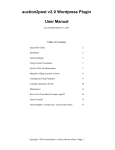
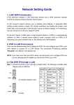
Signature Series
SATOMPC-2
ATOM PROCESSOR COMPUTER
USER MANUAL
V1.0
1|Page
Table of Contents INTRODUCTION ..........................................................................................3 IMPORTANT SAFETY PRECAUTIONS ......................................................5 General Safety ...........................................................................................5 Caution ......................................................................................................5 Power Safety .............................................................................................5 Installation Notes .......................................................................................6 FRONT & REAR PANEL DRAWINGS .........................................................7 PANEL DESCRIPTIONS ..............................................................................8 1. Power On/Off Button..............................................................................8 2. RESET Button .......................................................................................8 3. Fan Mode Control Button.......................................................................8 4. PWR and HD indicators .........................................................................8 5. AUTO and FULL Indicators ...................................................................8 6. USB 2.0 Port ..........................................................................................8 7. CFast Card Slot .....................................................................................8 8. Air intake filters ......................................................................................9 9. Main IEC Connector ..............................................................................9 10. PS2 Keyboard and Mouse Connector .................................................9 11. USB 2.0 Port ........................................................................................9 12. COM 1 Serial Port................................................................................9 13. VGA Video Output ..............................................................................9 14. Network Interface 1 (NIC1) ..................................................................9 15. USB 2.0 Port ........................................................................................9 16. Network Interface 2 (NIC2) ..................................................................9 17. HDMI Connector ..................................................................................9 18. Audio I/O ............................................................................................10 19. COM 2 Serial Port (RS232/422 Mode) ..............................................10 20. COM 2 Serial Port (RS485 Mode) .....................................................10 COM 2 Mode ...........................................................................................10 Enhanced Write Filter Explained (EWF) .....................................................12 What is EWF? ..........................................................................................12 Why use EWF? ........................................................................................12 How does EWF work? .............................................................................12 How is EWF configured? .........................................................................12 How is EWF configured? .........................................................................13 2|Page
INTRODUCTION
Congratulations on purchasing the Autograph Signature Series SATOMPC-2
compact computer.
The SATOMPC-2 is compact 1U form factor computer designed specifically
for the installation and rental audio markets. The unit is compact and virtually
silent for use in performance areas where extra noise is not wanted.
The unit incorporates many features of the Windows 7 Embedded operating
system to provide a robust and reliable PC of audio control and monitoring
applications.
Should you experience any problems with your SATOMPC-2 please contact:
Service Department
Autograph Sound Recording Ltd
2 Spring Place
London NW5 3BA
United Kingdom
Tel. +44 (0)20 7485 4515
Fax. +44 (0)20 7284 1233
Email. [email protected]
3|Page
4|Page
IMPORTANT SAFETY PRECAUTIONS
This section contains definitions, warnings, and practical information to ensure
a safe working environment. Please take time to read this section before
installing or using this unit. Please do not dispose of these instructions.
General Safety
Read these instructions.
• Heed all warnings.
• Follow all instructions.
• Do not use this apparatus near water.
• Do not expose this apparatus to rain or moisture.
• Clean only with dry cloth.
• Do not block any ventilation openings. Install in accordance with the
manufacturer’s instructions.
• Do not install near any heat sources such as radiators, heat registers,
stoves
or other apparatus (including amplifiers) that produce heat.
• There are no user-adjustments, or user-servicable items, inside this
apparatus.
Do not remove the covers of this apparatus; doing so will invalidate
your warranty.
• Adjustments or alterations to this apparatus may affect the
performance such that safety and/or international compliance
standards may no longer be met.
Caution
• Hazardous voltages may be present inside this apparatus.
• Do not operate this apparatus with the covers removed.
• To reduce the risk of electric shock, do not perform any servicing other
than that contained in these installation instructions unless you are
qualified to do so. Refer all servicing to qualified service personnel and
ensure that all power cords are disconnected when servicing this
apparatus.
Power Safety
• This apparatus is fitted with a universal power supply, approved and
certified for operation in this apparatus. There are no user-replaceable
fuses.
• Multiple power cords may be supplied with this unit – use only the
power cord appropriate to your local power wiring. Alternative power
cords may be used if rated 2.5A or above and fitted with a 3-pin
IEC320 connector.
5|Page
•
•
•
•
•
An external over-current protection device is required to protect the
wiring to this apparatus. This protection device must be installed
according to current wiring regulations. In certain countries this
function is supplied by use of a fused plug.
If an extension power cable or adaptor is used, ensure that the total
power rating of the power cable and/or adaptor is not exceeded.
An external disconnect device is required for this apparatus; a
detachable power cord, as fitted to this equipment, is a suitable
disconnect device. The power socket used for this apparatus should
be located nearby and be easily accessible.
All power cords must be disconnected to isolate this apparatus
completely.
Unplug this apparatus during an electrical storm or when unused for
long periods of time.
Installation Notes
• When installing this apparatus, either fix it into a standard 19" rack or
place the apparatus on a secure level surface.
• When this apparatus is rack mounted, fit all rack screws. Rack shelves
are recommended for this apparatus.
• Do not operate this apparatus whilst it is covered or boxed in any way.
• Ensure that no strain is placed on the cables connecting to this
apparatus. Ensure also that such cables are not placed where they
can be stepped on, pulled or tripped over.
6|Page
FRONT & REAR PANEL DRAWINGS
4
PW R
R ESE T
5
H DD
A UTO
FU LL
FA N
U SB
1
2
3
6
10
12
PS2 K/M
7
8
14
NIC 1
COM 1 RS2 32
USB 2.0
MA DE IN ENG LAND
9
11
VGA
USB 2.0
NIC 2
13
15
16
HDMI
17
LI NE
OUT
LI NE
IN
18
MIC
IN
COM 2
RS232
19
COM 2
RS485
20
21
7|Page
PANEL DESCRIPTIONS
1. Power On/Off Button
This momentary button is illuminated when power is applied to the unit so that
it can be easily located in low light conditions. Pressing this button turns on
the unit. Holding this button while the system is running will force a reset.
2. RESET Button
This momentary button forces a system reset when the computer is operating.
3. Fan Mode Control Button
In order to provide quieter operation the SATOMPC-2 has two fan modes
available. AUTO mode uses an internal temperature sensor to adjust the
speed of the fans internally. This is the normal operational mode and provides
near silent operation. FULL mode may be required in extreme operating
conditions or where noise is not an issue. This sets the internal fans to run at
full speed and does create some noise. The Fan Mode Control button is a
latching button that enable selection between AUTO and FULL fan modes.
The activated mode is displayed by the AUTO and FULL indicators. (5)
4. PWR and HD indicators
The PWR indicator indicates that there is power applied to the motherboard of
the computer. The computer is switched on.
The HD indicator indicates activity reading or writing to the internal CFast
permanent storage.
5. AUTO and FULL Indicators
The indicators show the current Fan Control Mode (see 3 above.)
6. USB 2.0 Port
This USB 2.0 Port operates at 480Mbps and and can be used for any USB 2.0
compliant device.
7. CFast Card Slot
Behind this cover is located the CFast card which the device uses for
permanent storage. CFast is a high speed SATA interface in a Compact
Flash form factor. THIS IS NOT A COMPACT FLASH CARD – If you try to
fit a compact flash card to this socket it will result in damage to the card
and the device. The CFast card is removable and can be moved to another
identical system if needed.
8|Page
8. Air intake filters
The SATOMPC-2 is designed to minimise airflow so these filters should stay
clean and only require cleaning every three to six months. If the unit is
operating if FULL fan mode the filters will need to be cleaned more regularly.
9. Main IEC Connector
The SATOMPC-2 will accept AC power 110V-240V @ 40-50Hz.
10. PS2 Keyboard and Mouse Connector
6 pin Female PS2 Keyboard/Mouse Connector
11. USB 2.0 Port
These USB 2.0 Port operate at 480Mbps and can be used for any USB 2.0
compliant device.
12. COM 1 Serial Port
9 Pin RS232 Serial Port.
Pin
1
2
3
4
5
6
7
8
9
Function
DCD
RXD
TXD
DTR
GND
DSR
RTS
CTS
RI
13. VGA Video Output
15pin VGA Video Output connector.
14. Network Interface 1 (NIC1)
1000-BaseT Network Interface.
15. USB 2.0 Port
These USB 2.0 Port operate at 480Mbps and can be used for any USB 2.0
compliant device.
16. Network Interface 2 (NIC2)
1000-BaseT Network Interface.
17. HDMI Connector
High-Definition Multimedia Interface which can be converted to DVI for a
secondary independent display.
9|Page
18. Audio I/O
3.5mm Jack connector allow for unbalance audio input and output.
19. COM 2 Serial Port (RS232/422 Mode)
9 Pin RS232 Serial Port.
Pin
1
2
3
4
5
6
7
8
9
Function
DCD
RXD
TXD
DTR
GND
DSR
RTS
CTS
RI
20. COM 2 Serial Port (RS485 Mode)
This connection allows for 2 Wire RS485 connections on a standard XLR
connector. This is suitable for connection to XTA processing equipment. This
facility is fitted with a one use protection device in case of accidental
connection to a PSU.
Pin
1
2
3
Description
GND
PS +
NEG -
COM 2 Mode
COM port 2 can be configured for use as RS232/422 or 485. This is achieved
from jumpers located on the motherboard of the computer. By default this is
set to RS485 operation.
10 | P a g e
11 | P a g e
Enhanced Write Filter Explained (EWF)
What is EWF?
Enhanced Write Filter is a feature of Windows Embedded operating systems
that enables more specific control of what and when information is written to
the hard disk of the computer.
Why use EWF?
The reasons for using EWF are two fold:
The SATOMPC is fitted with a very reliable solid state disk. Solid state disks
have many advantages in that they are very quick, they are silent and give off
very little heat. Also no moving parts means that they are extremely reliable.
Solid state drives do have one down side however in that they have a limited
amount of write cycles. Although this is a very large number if the disk is
written to in a specific place enough times the disk will fail. This is not a
problem under normal use, however, all operating systems cache files to disk
constantly which can lead to premature failure of the disk.
The second reason for using EWF is that it provides a certain amount of
protection from viruses and accidental corruption of files. Most shows once
they are up and running make very few changes to the system files of the PC
so with EWF enabled any problems that arise from a virus or deletion of
systems files can be solved with a quick reboot.
How does EWF work?
EWF works by redirecting the files that should be written to the hard disk to a
RAM overlay that is held in the computer memory. Hence if this overlay is not
committed to the hard disk at the end of the session the information is lost.
How is EWF configured?
When you receive a SATOMPC it will have EWF enabled and configured on
the C (System Drive) only. This means that any changes to files on the C
drive including any system configuration changes or system preferences that
are stored in the registry are not permanent until they are committed by using
the Signature Series EWF Configuration Utility.
IF YOU DO NOT COMMIT CHANGES WHEN YOU REBOOT ANY
MODIFICATIONS TO THE SYSTEM DRIVE WILL BE LOST.
The D (DATA) drive is not configured for EWF. Any information written to the
D drive will persist without any further action. Therefore, it is sensible to put
any data that changes frequently and needs to be saved (such as show files)
on the D drive only.
THE D DRIVE IS NOT PROTECTED BY EWF ALL CHANGES TO FILES ON
THE D DRIVE WILL PERSIST WITHOUT ANY FURTHER ACTION.
12 | P a g e
How is EWF configured?
EWF is configured using the Signature Series EWF Configuration Utility which
can be found in the start menu.
This application allows control of all the features of EWF. Any changes made
to EWF will require a restart of the computer.
Commit ChangesThis button enables all changes to drive C to be committed to the hard disk at
the next reboot. Once you press Commit Changes the state of the C Drive will
be written to the hard disk at the next reboot. It is recommended that you only
commit changes when absolutely necessary. Data written to the D drive does
not require Commit Changes. Committing changes too often exposes the
operating system to viruses which may have infected since the last commit.
Enable and DisableEnables and disables the EWF functions on the C drive. This mode is useful
when initially installing software that requires restarts but it is not
recommended to leave EWF disabled. Both functions require a reboot
immediately to take effect.
13 | P a g e