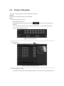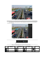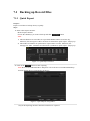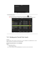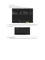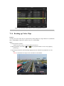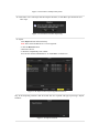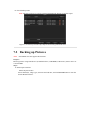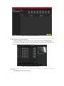
1
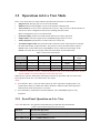
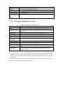
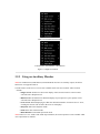
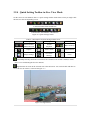
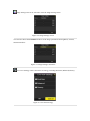
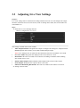
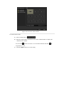
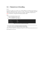
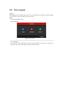
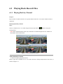
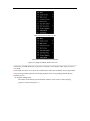
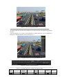
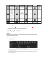
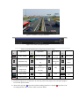
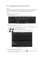
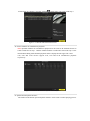
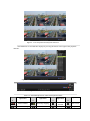
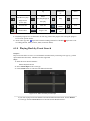
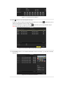
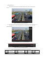
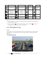
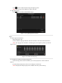
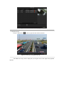
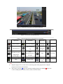
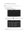
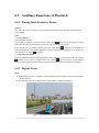
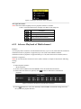
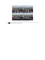
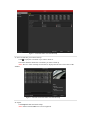
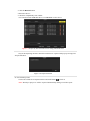
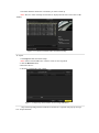
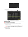
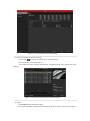
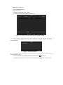
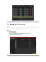
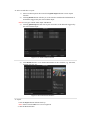
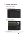
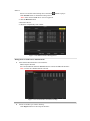
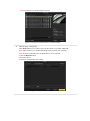
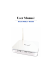
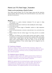
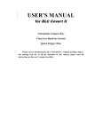
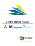
User Manual of DS-9600/8600/7700/7600 Series NVR 3.1 Introduction of Live View Live view shows you the video image getting from each camera in real time. The NVR automatically enters Live View mode when powered on. It is also at the very top of the menu hierarchy, thus pressing the ESC many times (depending on which menu you’re on) brings you to the Live View mode. Live View Icons In the live view mode, there are icons at the right top of the screen for each channel, showing the status of the record and alarm in the channel, so that you can know whether the channel is recorded, or whether there are alarms occur as soon as possible. Table 3. 1 Description of Live View Icons Icons Description Alarm (video loss, tampering, motion detection or sensor alarm) Record (manual record, schedule record, motion detection or alarm triggered record) Alarm & Record 39 User Manual of DS-9600/8600/7700/7600 Series NVR 3.2 Operations in Live View Mode In live view mode, there are many functions provided. The functions are listed below. • • • Single Screen: showing only one screen on the monitor. Multi-screen: showing multiple screens on the monitor simultaneously. Auto-switch: the screen is auto switched to the next one. And you must set the dwell time for each screen on the configuration menu before enabling the auto-switch. Menu>Configuration>Live View>Dwell Time. • • • • Start Recording: normal record and motion detection record are supported. Output Mode: select the output mode to Standard, Bright, Gentle or Vivid. All-day Playback: playback the recorded videos for current day. Aux/Main output switch: the NVR checks the connection of the output interfaces to define the main and auxiliary output interfaces. The priority level for the main and aux output is HDMI>VGA>CVBS. This means if the HDMI is used, it will be the main output. If the HDMI is not used, the VGA output will be the main output. See the table below. Table 3. 2 Priorities of Interfaces HDMI VGA CVBS Main output Auxiliary output 1 √ √ √ HDMI VGA 2 √ × √ HDMI CVBS 3 × √ √ VGA CVBS 4 × × √ CVBS √ means the interface is in use, × means the interface is out of use or the connection is invalid. And the HDMI, VGA and CVBScan be used at the same time. When the aux output is enabled, the main output can’t do any operation, and you can do some basic operation on the live view mode for the Aux output. Notes: 1. For LTN7616, there is only one audio output, the VGA output has a higher priority over CVBS output. When you enable the audio in both the CVBS and VGA audio output, the audio from the audio out interface is for VGA. 2. For LTN7604-P4, LTN7608-P4 and LTN7608-P8, VGA and HDMI output are only supported. 3.2.1 Front Panel Operation on Live View Note: This function is not supported with LTN7604-P4, LTN7608-P4, LTN7608-P8. Table 3. 3 Front Panel Operation in Live View Functions Front Panel Operation Show single screen Press the corresponding Alphanumeric button. E.g. Press 2 to display only the screen for channel 2. Show multi-screen Press the PREV/FOCUS- button. 40 User Manual of DS-9600/8600/7700/7600 Series NVR Manually screens switch Next screen: right/down direction button. Previous screen: left/up direction button. Auto-switch Press Enter button. All-day playback Press Play button. Switch between main and aux output Press Main/Aux button. 3.2.2 Using the Mouse in Live View Table 3. 4 Mouse Operation in Live View Name Description Menu Enter the main menu of the system by right clicking the mouse. Single Screen Switch to the single full screen by choosing channel number from the dropdown list. Multi-screen Adjust the screen layout by choosing from the dropdown list. Previous Screen Switch to the previous screen. Next Screen Switch to the next screen. Start/Stop Auto-switch Enable/disable the auto-switch of the screens. Start Recording Start normal recording or motion detection recording of all channels. All-day Playback Playback the video of the selected channel. Output Mode Four modes of output supported, including Standard, Bright, Gentle and Vivid. Aux Monitor Switch to the auxiliary output mode and the operation for the main output is disabled. Note: The dwell time of the live view configuration must be set before using Start Auto-switch. Note: If you enter Aux monitor mode and the Aux monitor is not connected, the mouse operation is disabled; you need to switch back to the Main output with the MAIN/AUX button on the front panel or remote. Note: If the corresponding camera supports intelligent function, the Reboot Intelligence option is included when right-clicking mouse on this camera. 41 User Manual of DS-9600/8600/7700/7600 Series NVR LTN7732-P8/LTN7616/LTN7632 LTN7604-P4, LTN7608-P4, LTN7608-P8 Figure 3. 1 Right-click Menu 3.2.3 Using an Auxiliary Monitor Note: For LTN7604-P4, LTN7608-P4, LTN7608-P8 do not have an auxiliary output, the below function is not supported with it. Certain features of the Live View are also available while in an Aux monitor. These features include: • Single Screen: Switch to a full screen display of the selected camera. Camera can be selected from a dropdown list. • Multi-screen: Switch between different display layout options. Layout options can be selected from a dropdown list. • Next Screen: When displaying less than the maximum number of cameras in Live View, clicking this feature will switch to the next set of displays. • Playback: Enter into Playback mode. • PTZ: Enter PTZ Control mode. • Main Monitor: Enter Main operation mode. Note: In the live view mode of the main output monitor, the menu operation is not available while Aux output mode is enabled. 42 User Manual of DS-9600/8600/7700/7600 Series NVR 3.2.4 Quick Setting Toolbar in Live View Mode On the screen of each channel, there is a quick setting toolbar which shows when you single click the mouse in the corresponding screen. L LTN7732-P8/LTN7616/LTN7632 LTN7604-P4, LTN7608-P4, LTN7608-P8 Figure 3. 2 Quick Setting Toolbar Table 3. 5 Description of Quick Setting Toolbar Icons Icons Description / Icons Description Icons Description Enable/Disable Manual Record Instant Playback / Mute/Audio on Capture PTZ Control Digital Zoom Image Settings Live View Strategy Close Instant Playback only shows the record in last five minutes. If no record is found, it means there is no record during the last five minutes. Digital Zoom can zoom in the selected area to the full screen. You can left-click and draw to select the area to zoom in, as shown in Figure 3. 3. Figure 3. 3 Digital Zoom 43 User Manual of DS-9600/8600/7700/7600 Series NVR Image Settings icon can be selected to enter the Image Settings menu. Figure 3. 4 Image Settings- Preset You can also choose the Customize mode to set the image parameters like brightness, contrast, saturation and hue. Figure 3. 5 Image Settings- Customize Live View Strategy can be selected to set strategy, including Real-time, Balanced, Fluency. Figure 3. 6 Live View Strategy 44 User Manual of DS-9600/8600/7700/7600 Series NVR 3.3 Adjusting Live View Settings Purpose: Live View settings can be customized according to different needs. You can configure the output interface, dwell time for screen to be shown, mute or turning on the audio, the screen number for each channel, etc. Steps: 1. Enter the Live View Settings interface. Menu> Configuration> Live View Figure 3. 7 Live View-General The settings available in this menu include: • • • • • • Video Output Interface: Designates the output to configure the settings for. Outputs include HDMI (depends on the model), VGA, Main CVBS and Spot Output. Notes: No CVBS spot out for LTN7732-P8/LTN7616/LTN7632, LTN7600-P series NVR. Live View Mode: Designates the display mode to be used for Live View. Dwell Time: The time in seconds to dwell between switching of channels when enabling auto-switch in Live View. Enable Audio Output: Enables/disables audio output for the selected video output. Event Output: Designates the output to show event video. Full Screen Monitoring Dwell Time: The time in seconds to show alarm event screen. 2. Setting Cameras Order 45 User Manual of DS-9600/8600/7700/7600 Series NVR Figure 3. 8 Live View- Camera Order To set the camera order: 1) Select a View mode in . 2) Select the small window, and double-click on the channel number to display the channel on the window. You can click button to start live view for all the channels and click stop all the live view. 3) Click the Apply button to save the setting. 46 to User Manual of DS-9600/8600/7700/7600 Series NVR 3.4 Channel-zero Encoding Purpose: Sometimes you need to get a remote view of many channels in real time from web browser or CMS(Client Management System) software, in order to decrease the bandwidth requirement without affecting the image quality, channel-zero encoding is supported as an option for you. Note: This function is not supported with LTN7600-P Series NVR. Steps: 1. Enter the Live View Settings interface. Menu> Configuration> Live View 2. Select the Channel-Zero Encoding tab. Figure 3. 9 Live View- Channel-Zero Encoding 3. Check the checkbox after Enable Channel Zero Encoding. 4. Configure the Frame Rate, Max. Bitrate Mode and Max. Bitrate. After you set the Channel-Zero encoding, you can get a view in the remote client or IE browser of all the channels in one screen. 47 User Manual of DS-9600/8600/7700/7600 Series NVR 3.5 User Logout Purpose: After logging out, the monitor turns to the live view mode and if you want to do some operation, you need to enter user name and password tog in again. Steps: 1. Enter the Shutdown menu. Menu>Shutdown Figure 3. 10 Shutdown 2. Click Logout. Note: After you have logged out the system, menu operation on the screen is invalid. It is required to input a user name and password to unlock the system. 48 User Manual of DS-9600/8600/7700/7600 Series NVR Chapter 6 Playback 81 User Manual of DS-9600/8600/7700/7600 Series NVR 6.1 Playing Back Record Files 6.1.1 Playing Back by Channel Purpose: Play back the recorded video files of a specific channel in the live view mode. Channel switch is supported. Instant playback by channel Steps: Choose a channel in live view mode using the mouse and click the button in the quick setting toolbar. Note: In the instant playback mode, only record files recorded during the last five minutes on this channel will be played back. Figure 6. 1 Instant Playback Interface All-day Playback by channel 1. Enter the All-day Playback interface. Mouse: right click a channel in live view mode and select All-day Playback from the menu, as shown in Figure 6. 2. 82 User Manual of DS-9600/8600/7700/7600 Series NVR LTN7732/LTN7616/LTN7732-P8 LTN7604-P4/LTN7608-P4/LTN7608-P8 Figure 6. 2 Right-click Menu under Live View Front Panel: press PLAY button to play back record files of the channel under single-screen live view mode. Under multi-screen live view mode, the recorded files of the top-left channel will be played back. Note: Pressing numerical buttons will switch playback to the corresponding channels during playback process. 2. Playback management. The toolbar in the bottom part of Playback interface can be used to control playing progress, as shown in Figure 6. 3. 83 User Manual of DS-9600/8600/7700/7600 Series NVR Figure 6. 3 All-day Playback Interface The channel and time selection menu displays by moving the mouse to the right of the playback interface. Click the channel(s) if you want to switch playback to another channel or execute simultaneous playback of multiple channels, as shown in Figure 6. 4 . Figure 6. 4 All-day Playback Interface with Channel List Figure 6. 5 Toolbar of All-day Playback Table 6. 1 Detailed Explanation of All-day-playback Toolbar Butto n Operation Button Operation / Audio / Start/Stop 84 Button Operation 30s forward Button Operatio n 30s User Manual of DS-9600/8600/7700/7600 Series NVR / on/Mute clipping Add default tag Add customized tag Tag managemen t Speed down Pause reverse play/ Reverse play/ Single-fram e reverse play Pause play/Play/Si ngle-frame play Stop Speed up Previous day Next day Hide Exit Process bar Video type bar / reverse Note: 1. Playback progress bar: use the mouse to click any point of the progress bar or drag the progress bar to locate special frames. 2. About video type bar: represents normal recording (manual or schedule); represents event recording (motion, alarm, motion | alarm, motion & alarm). 6.1.2 Playing Back by Time Purpose: Play back video files recorded in specified time duration. Multi-channel simultaneous playback and channel switch are supported. Steps: 1. Enter playback interface. Menu>Playback 2. Set search conditions and click the Playback button to enter Playback interface. Figure 6. 6 Video Search by Time In the Playback interface: The toolbar in the bottom part of Playback interface can be used to control playing process, as shown in Figure 6. 7. 85 User Manual of DS-9600/8600/7700/7600 Series NVR Figure 6. 7 Interface of Playback by Time Figure 6. 8 Toolbar of Playback by Time Table 6. 2 Detailed Explanation of Playback-by-time Toolbar Butto n Operation Butto n Operation / Audio on/Mute / Start/Stop clipping 30s forward 30s reverse Add default tag Add customized tag Tag manageme nt Speed down Pause reverse play/Reverse play/ Single-frame reverse play Pause play/Play/Single-fr ame play Stop Speed up Exit Hide Progress bar / Video search / Butto n Operation Butto n Operation Video type bar Note: 1. Playback progress bar: use the mouse to click any point of the progress bar or drag the progress bar to locate special frames. 2. About video type bar: represents normal recording (manual or schedule); represents event recording (motion, alarm, motion | alarm, motion & alarm). 86 User Manual of DS-9600/8600/7700/7600 Series NVR 6.1.3 Playing Back by Normal Video Search Purpose: Play back video files searched out by restricting recording type and recording time. The video files in the result list are played back sequentially and channel switch is supported. Recording types contain Normal, Motion, Alarm, Motion / Alarm, Motion & Alarm, Manual and All. Steps: 1. Enter Normal Video Search interface. Menu>Playback>Normal Set search condition and click Search button to enter the Search Result interface. Figure 6. 9 Normal Video Search 2. Check detail information of record files. If you want to know the record information of every camera, click Detail button and will pop up a window to show them, as shown in Figure 6. 10. Click or can switch to the previous or next page. Click Previous or Next button can switch to the date before or after the present date. Click or at the left-top of the window can zoom in or out of the time bar Figure 6. 10 Record Information 3. Choose a record file you want to play back. If there is only one channel in the search result, clicking Playback interface of this channel. 87 button takes you to Full-screen User Manual of DS-9600/8600/7700/7600 Series NVR If more than one channel is optional, clicking button takes you to step 3and step 4. Figure 6. 11 Result of Normal Video Search 4. Choose channels for simultaneous playback. Note: Optional channels for simultaneous playback are the same as the channels chosen to search record files in step 1. And the channel with the recorded file selected in step 2 is the main channel during multi-channel playback and it is displayed at the upper left corner. 4-ch, 8-ch and 16-ch devices support 4-ch, 8-ch and 16-ch simultaneous playback respectively. Figure 6. 12 Select Channels for Synchronous Playback 5. Synchronous Playback interface. The toolbar in the bottom part of Playback interface can be used to control playing process. 88 User Manual of DS-9600/8600/7700/7600 Series NVR Figure 6. 13 4-ch Synchronous Playback Interface The hidden list of recorded files displays by moving the mouse to the right of the playback interface. Figure 6. 14 4-ch Synchronous Playback Interface with Video List Figure 6. 15 Toolbar of Normal Playback Table 6. 3 Detailed Explanation of Normal Playback Toolbar Butto n Operation Butto n Operation / Audio on/Mute / Start/Stop clipping 30s forward 30s reverse Add customized Tag Speed Add default tag 89 Butto n Operation Butto n Operation User Manual of DS-9600/8600/7700/7600 Series NVR tag / manageme nt down Pause play/Play/Single-fr ame play Stop Speed up Previous file Next file Video search Exit Hide toolbar Progress bar Video type bar Pause reverse play/Reverse play/ Single-frame reverse play / Note: 1. Playback progress bar: use the mouse to click any point of the progress bar or drag the progress bar to locate special frames. 2. About video type bar: represents normal recording (manual or schedule); represents event recording (motion, alarm, motion | alarm, motion & alarm). 6.1.4 Playing Back by Event Search Purpose: Play back record files on one or several channels searched out by restricting event type (e.g. alarm input and motion detection). Channel switch is supported. Steps: 1. Enter the Event Search interface. Menu>Playback>Event 2. Select Alarm Input as the event type. 3. Click Search button to enter the Search Result interface. Figure 6. 16 Video Search by Alarm Input If you want to play back recorded files associated with motion detection, choose Motion as event type and click Search button to enter the Search Result interface. 90 User Manual of DS-9600/8600/7700/7600 Series NVR Figure 6. 17 Video Search by Motion 4. Click button to enter the Playback interface. If there is only one channel is triggered by an alarm input, clicking Full-screen Playback interface of this channel. button takes you to If several channels are triggered, clicking button takes you to step 7and then step 8. Note: Pre-play and post-play can be configured. Figure 6. 18 Result of Video Search by Alarm Input 5. Click Details button to view detailed information of the record file, e.g. start time, end time, file size, etc. Figure 6. 19 Event Details Interface 91 User Manual of DS-9600/8600/7700/7600 Series NVR 6. Playback interface. The toolbar in the bottom part of Playback interface can be used to control playing process. Figure 6. 20 Interface of Playback by Event The hidden list of events will be displayed by moving the mouse to the right of the playback interface. Figure 6. 21 Playback Interface with Alarm Input List Figure 6. 22 Toolbar of Playback by Event Table 6. 4 Detailed Explanation of Playback-by-event Toolbar Butto n Operation Butto n Operation / Audio on/Mute / Start/Stop clipping 92 Butto n Operation 30s Butto n Operation 30s reverse User Manual of DS-9600/8600/7700/7600 Series NVR forward / Add default tag Add customized tag Tag manageme nt Speed down Pause reverse play/Reverse play/ Single-frame reverse play Pause play/Play/Single-fr ame play Stop Speed up Previous event Next event Event search Exit Hide Progress bar Video type bar / Note: 1. Playback progress bar: use the mouse to click any point of the progress bar or drag the progress bar to locate special frames. 2. About video type bar: represents normal recording (manual or schedule); represents event recording (motion, alarm, motion | alarm, motion & alarm). 6.1.5 Playing Back by Tag Purpose: Video tag allows you to record related information like people and location of a certain time point during playback. You are also allowed to use video tag(s) to search for record files and position time point. Before playing back by tag: 1. Enter Playback interface. Figure 6. 23 Interface of Playback by Time Click button to add default tag. 93 User Manual of DS-9600/8600/7700/7600 Series NVR Click button to add customized tag and input tag name. Note: Max. 64 tags can be added to a single video file. 2. Tag management. Click button to check, edit and delete tag(s). Figure 6. 24 Tag Management Interface Steps: 1. Enter Tag Search interface. Menu>Playback>Tag Choose channels, tag type and time, and click Search to enter Search Result interface. Note: Two tag types are selectable: All and Tag Keyword. Input keyword if you choose Tag Keyword. Figure 6. 25 Video Search by Tag 2. Set playback conditions and tag management. Choose the tag name of the recorded file you want to play back; it can be edited or deleted. Pre-play and post-play time can be set according to actual needs. Note: Pre-play time and post-play time is added to the time point of the tag. 94 User Manual of DS-9600/8600/7700/7600 Series NVR Figure 6. 26 Result of Video Search by Tag 3. Playback by tag. Choose a tag and click button to play back the related record file. Figure 6. 27 Interface of Playback by Tag The hidden list of tags will be displayed by moving the mouse to the right of the playback interface. 95 User Manual of DS-9600/8600/7700/7600 Series NVR Figure 6. 28 Interface of Playback by Tag with Video List Figure 6. 29 Toolbar of Playback by Tag Table 6. 5 Detailed Explanation of Playback-by-tag Toolbar Butto n Operation Butto n Operation / Audio on/Mute / Start/Stop clipping 30s forward 30s reverse Add default tag Add customized tag Tag manageme nt Speed down Pause reverse play/Reverse play/ Single-frame reverse play Pause play/Play/Single-fr ame play Stop Speed up Previous tag Next tag Tag search Exit Hide Progress bar Video type bar / / Butto n Operation Butto n Operation Note: 1. Playback progress bar: use the mouse to click any point of the progress bar or drag the progress bar to locate special frames. 2. About video type bar: represents normal recording (manual or schedule); represents event recording (motion, alarm, motion | alarm, motion & alarm). 96 User Manual of DS-9600/8600/7700/7600 Series NVR 6.1.6 Playing Back by System Logs Purpose: Play back record file(s) associated with channels after searching system logs. Steps: 1. Enter Log Information interface. Menu>Maintenance>Log Information 2. Click Log Search tab to enter Playback by System Logs. Set search time and type and click Search button. Figure 6. 30 System Log Search Interface 3. Choose a log with record file and click button to enter Playback interface. Note: If there is no record file at the time point of the log, the message box “no related record file” will pop up. Figure 6. 31 Result of System Log Search 4. Playback interface. The toolbar in the bottom part of Playback interface can be used to control playing process. 97 User Manual of DS-9600/8600/7700/7600 Series NVR Figure 6. 32 Interface of Playback by Log 98 User Manual of DS-9600/8600/7700/7600 Series NVR 6.2 Auxiliary Functions of Playback 6.2.1 Playing Back Frame by Frame Purpose: Play video files frame by frame, in case of checking image details of the video when abnormal events happen. Steps: • Using a Mouse: Go to Playback interface. If you choose playback of the record file: click button until the speed changes to Single frame and one click on the playback screen represents playback of one frame. If you choose adverse playback of the record file: click button until the speed changes to Single frame and one click on the playback screen represents adverse playback of one frame. It is also feasible to use button in toolbar. • Using the Front Panel: Rotate and hold the outer ring on Jog Shuttle counter clockwise (for LTN7732 only) or click the button to set the speed to Single frame. One click on button, one click on the playback screen or Enter button on the front panel represents playback or adverse playback of one frame. 6.2.2 Digital Zoom Steps: 1. Right click the mouse on a channel under playback and choose Digital Zoom to enter Digital Zoom interface. 2. Drag and draw the red rectangle and the image within it will be quadrupled. Figure 6. 33 Draw Area for Digital Zoom 99 User Manual of DS-9600/8600/7700/7600 Series NVR Figure 6. 34 Right-click Menu under Playback The right-click menu: Note: This menu differs slightly from one playback interface to another. Table 6. 6 Detailed Explanation of Right-click Menu under Playback Button Function Return to Search interface Enter Digital Zoom interface Show & hide control interface Return to Playback interface 6.2.3 Adverse Playback of Multi-channel Purpose: You can play back record files of multi-channel adversely. Up to 16-ch (with 1280*720 resolution) simultaneous adverse playback is supported; up to 4-ch (with 1920*1080P resolution) simultaneous adverse playback is supported and up to 1-ch (with 2560*1920 resolution) adverse playback is supported. Note: We use the interface of LTN7732 series (unless stated) as example to describe the following settings. Steps: 1. Enter Playback interface. Menu>Playback 2. Set the search condition and click Search to enter the Search Result interface. 3. If more than one channel is optional, click playback. to choose channels for simultaneous Figure 6. 35 Select Channels for Synchronous Playback 4. Check checkbox to select the channel(s) and click OK to confirm the settings and enter the synchronous playbck interface. 100 User Manual of DS-9600/8600/7700/7600 Series NVR Figure 6. 36 4-ch Synchronous Playback Interface Click to play back the record files adversely. 101 User Manual of DS-9600/8600/7700/7600 Series NVR 6.3 Picture Playback Note: The LTN7600-P series does not support this function. Purpose: Search and view captured pictures stored in HDD. Steps: 1. Enter Picture Search interface. Menu>Playback>Picture Set channel, picture type and time and click button to enter Search Result interface. Note: Picture types include Normal, Motion, Alarm, Motion / Alarm, Motion & Alarm, Capture and Continuous Capture. Figure 6. 37 Picture Search 2. View pictures. Choose a picture you want to view and click button. Figure 6. 38 Result of Picture Search 3. Picture Playback interface. The toolbar in the bottom part of Playback interface can be used to control playing process. 102 User Manual of DS-9600/8600/7700/7600 Series NVR Figure 6. 39 Picture Playback Interface The hidden list of captured pictures will be displayed by moving the mouse to the right of the playback interface. Figure 6. 40 Playback Interface with Picture List Figure 6. 41 Picture Playback Toolbar Table 6. 7 Detailed Explanation of Picture-playback Toolbar Butto n Function Play reverse Picture search Butto n Function Button Function Play Previous picture Hide Exit 103 Butto n Function Next picture User Manual of DS-9600/8600/7700/7600 Series NVR Chapter 7 Backup 104 User Manual of DS-9600/8600/7700/7600 Series NVR 7.1 Backing up Record Files 7.1.1 Quick Export Purpose: Export record files to backup device(s) quickly. Steps: 1. Enter Video Export interface. Menu>Export>Normal Choose the channel(s) you want to back up and click button. Note: 1) The time duration of record files on a specified channel cannot exceed one day. Otherwise, the message box “Max. 24 hours are allowed for quick export.” will pop up. 2) The number of channels for synchronous export cannot exceed 4. Otherwise, the message box “Max. 4 channels are allowed for synchronous quick export.” will pop up. Figure 7. 1 Quick Export Interface 2. Click on the button to start exporting. Note: Here we use USB Flash Drive and please refer to the next section Normal Backup for more backup devices supported by the device. Figure 7. 2 Quick Export using USB1-1 Stay in the Exporting interface until all record files are exported. 105 User Manual of DS-9600/8600/7700/7600 Series NVR Figure 7. 3 Export Finished 3. Check backup result. Choose the record file in Export interface and click button to check it. Note: The Player player.exe will be exported automatically during record file export. Figure 7. 4 Checkup of Quick Export Result Using USB1-1 7.1.2 Backing up by Normal Video Search Purpose: The record files can be backup to various devices, such as USB devices (USB flash drives, USB HDDs, USB writer), SATA writer and e-SATA HDD. Backup using USB flash drives and USB HDDs Steps: 1. Enter Export interface. Menu>Export>Normal 2. Set search condition and click Search button to enter the search result interface. 106 User Manual of DS-9600/8600/7700/7600 Series NVR Figure 7. 5 Normal Video Search for Backup 3. Select record files you want to back up. Click to play the record file if you want to check it. Check the checkbox before the record files you want to back up. Note: The size of the currently selected files is displayed in the lower-left corner of the window. Figure 7. 6 Result of Normal Video Search for Backup 4. Export. Click Export button and start backup. Note: If the inserted USB device is not recognized: 107 User Manual of DS-9600/8600/7700/7600 Series NVR • Click the Refresh button. • Reconnect device. • Check for compatibility from vendor. You can also format USB flash drives or USB HDDs via the device. Figure 7. 7 Export by Normal Video Search using USB Flash Drive Stay in the Exporting interface until all record files are exported with pop-up message box “Export finished”. Figure 7. 8 Export Finished 5. Check backup result. Choose the record file in Export interface and click button to check it. Note: The Player player.exe will be exported automatically during record file export. 108 User Manual of DS-9600/8600/7700/7600 Series NVR Figure 7. 9 Checkup of Export Result using USB Flash Drive Backup using USB writer and SATA writer Steps: 1. Enter Export interface. Menu>Export>Normal 2. Set search condition and click Search button to enter the search result interface. Figure 7. 10 Normal Video Search for Backup 3. Select record files you want to back up. Click button to play the record file if you want to check it. 109 User Manual of DS-9600/8600/7700/7600 Series NVR Check the checkbox before the record files you want to back up. Note: The size of the currently selected files is displayed in the lower-left corner of the window. Figure 7. 11 Result of Normal Video Search for Backup 4. Export. Click Export button and start backup. Note: If the inserted USB writer or SATA writer is not recognized: • Click the Refresh button. • Reconnect device. • Check for compatibility from vendor. Figure 7. 12 Export by Normal Video Search using USB Writer Stay in the Exporting interface until all record files are exported with pop-up message box “Export finished”. 110 User Manual of DS-9600/8600/7700/7600 Series NVR Figure 7. 13 Export Finished 5. Check backup result. Choose the record file in Export interface and click button to check it. Note: The Player player.exe will be exported automatically during record file export. Figure 7. 14 Checkup of Export Result using USB Writer Backup using eSATA HDDs Note: The LTN7600-P does not support this function. Steps: 1. Enter Record>Advanced and set the working mode of eSATA HDD at “Export”. Menu>Record>Advanced Choose eSATA and set its mode at Export. Click Yes when pop-up message box “System will reboot automatically if the usage of eSATA is changed. Continue?” Note: The working modes of eSATA HDD contain Record/Capture and Export. And changes in working mode will take effective after rebooting the device. 2. Enter Export interface. Menu>Export>Normal Set search condition and click Search button to enter the search result interface. 111 User Manual of DS-9600/8600/7700/7600 Series NVR Figure 7. 15 Normal Video Search for Backup 3. Select record files you want to back up. Click button to play the record file if you want to check it. Tick record files you want to back up. Note: The size of the currently selected files is displayed in the lower-left corner of the window. Figure 7. 16 Result of Normal Video Search for Backup 4. Export. Click Export button and start backup. Note: Please format the eSATA first when using it for the first time. If the inserted eSATA 112 User Manual of DS-9600/8600/7700/7600 Series NVR HDD is not recognized: • Click the Refresh button. • Reconnect device. • Check for compatibility from vendor. You can also format SATA HDD via the device. Figure 7. 17 Export by Normal Video Search Using eSATA HDD Stay in the Exporting interface until all record files are exported with pop-up message “Export finished”. Figure 7. 18 Export Finished 5. Check backup result. Choose the record file in Export interface and click button to check it. Note: The Player player.exe will be exported automatically during record file export. 113 User Manual of DS-9600/8600/7700/7600 Series NVR Figure 7. 19 Checkup of Export Result Using eSATA HDD 7.1.3 Backing up by Event Search Purpose: Back up event-related record files using USB devices (USB flash drives, USB HDDs, USB writer), SATA writer or e-SATA HDD. Quick Backup and Normal Backup are supported. Steps: 1. Enter Export interface. Menu>Export>Event 1) Select “Alarm Input” from the dropdown list of Event Type. 2) Select the alarm input No. and time. 3) Click Search button to enter the Search Result interface. Figure 7. 20 Event Search for Backup 114 User Manual of DS-9600/8600/7700/7600 Series NVR 2. Select record files to export. 1) Select an alarm input in the list and click Quick Export button to enter Export interface. 2) Clicking Details button will take you to the interface with detailed information of all channels triggered by the selected alarm input. Note: Event types contain Alarm Input and Motion. 3) Clicking Quick Export button will export record files of all channels triggered by the selected alarm input. Figure 7. 21 Result of Event Search 4) Click Details button to view detailed information of the record file, e.g. start time, end time, file size, etc. Figure 7. 22 Event Details Interface 3. Export. Click the Export button and start back up. Note: If the inserted USB device is not recognized: • Click the Refresh button. 115 User Manual of DS-9600/8600/7700/7600 Series NVR • Reconnect device. • Check for compatibility from vendor. You can also format USB flash drive or USB HDDs via the device. Figure 7. 23 Export by Event Using USB Flash Drive Stay in the Exporting interface until all record files are exported with pop-up message “Export finished”. Figure 7. 24 Export Finished 4. Check backup result. Note: The Player player.exe will be exported automatically during record file export. 116 User Manual of DS-9600/8600/7700/7600 Series NVR Figure 7. 25 Checkup of Event Export Result Using USB Flash Drive 7.1.4 Backing up Video Clips Purpose: You may also select video clips to export directly during Playback, using USB devices (USB flash drives, USB HDDs, USB writer), SATA writer or e-SATA HDD. Steps: 1. Enter Playback interface. Please refer to Chapter 7.1 Playing Back Record Files. 2. During playback, use buttons and in the playback toolbar to start or stop clipping record file(s). 3. Quit Playback interface after finishing clipping and you will then be prompted to save the clips. Note: A maximum of 30 clips can be selected for each channel. 117 User Manual of DS-9600/8600/7700/7600 Series NVR Figure 7. 26 Interface of Playback by Time 4. Click Yes to save video clips and enter Export interface, or click No to quit and do not save video clips. Figure 7. 27 Attention to Video Clip Saving 5. Export. Click Export button and start backup. Note: If the inserted USB device is not recognized: • Click the Refresh button. • Reconnect device. • Check for compatibility from vendor. You can also format USB flash drive or USB HDDs via the device. Figure 7. 28 Export Video Clips Using USB Flash Drive Stay in the Exporting interface until all record files are exported with pop-up message “Export finished”. Figure 7. 29 Export Finished 118 User Manual of DS-9600/8600/7700/7600 Series NVR 6. Check backup result. Note: The Player player.exe will be exported automatically during record file export. Figure 7. 30 Checkup of Video Clips Export Result Using USB Flash Drive 7.2 Backing up Pictures Note: LTN7600-P does not support this function. Purpose: Back up pictures using USB devices (USB flash drives, USB HDDs, USB writer), SATA writer or e-SATA HDD. Steps: 1. Enter Export interface. Menu>Export>Picture Select channel(s), image type, start time and end time, and click Search button to enter the Search Result interface. 119 User Manual of DS-9600/8600/7700/7600 Series NVR Figure 7. 31 Picture Search for Backup 2. Select pictures you want to back up. Check the checkbox before the pictures you want to back up and click Export button. Note: Here we take USB flash drive as an example. For more backup devices, please refer to chapter Backing up by Normal Video Search. Figure 7. 32 Result of Picture Search 3. Export. Click Export button and start backup. 120 User Manual of DS-9600/8600/7700/7600 Series NVR Figure 7. 33 Export Pictures Using USB Flash Drive Stay in the Exporting interface until all record files are exported with pop-up message “Export finished”. Figure 7. 34 Export Finished 4. Check backup result. Figure 7. 35 Checkup of Picture Export Using USB Flash Drive 121 User Manual of DS-9600/8600/7700/7600 Series NVR 7.3 Managing Backup Devices Management of USB flash drives, USB HDDs and eSATA HDDs. 1. Enter Search Result interface of record files. Menu>Export>Normal Set search condition and click Search button to enter Search Result interface. Note: At least one channel shall be selected. Figure 7. 36 Normal Video Search for Backup 2. Select record files you want to back up. Click Export button to enter Export interface. Note: At least one record file shall be selected. Figure 7. 37 Result of Normal Video Search for Backup 3. Backup device management. Click New Folder button if you want to create a new folder in the backup device. Select a record file or folder in the backup device and click 122 button if you want to User Manual of DS-9600/8600/7700/7600 Series NVR delete it. Select a record file in the backup device and click Click Format button to format the backup device. Note: If the inserted USB device is not recognized: button to play it. • Click the Refresh button. • Reconnect device. • Check for compatibility from vendor. Figure 7. 38 USB Flash Drive Management Management of USB writers and DVD-R/W 1. Enter Search Result interface of record files. Menu>Export>Normal Set search condition and click Search button to enter Search Result interface. Note: At least one channel shall be selected. Figure 7. 39 Normal Video Search for Backup 2. Select record files you want to back up. Click Export button to enter Export interface. 123 User Manual of DS-9600/8600/7700/7600 Series NVR Note: At least one record file shall be selected. Figure 7. 40 Result of Normal Video Search for Backup 3. Backup device management. Click Erase button if you want to erase the files from a re-writable CD/DVD. Note: There must be a re-writable CD/DVD when you make this operation. Note: If the inserted USB writer or DVD-R/W is not recognized: • Click the Refresh button. • Reconnect device. • Check for compatibility from vendor. Figure 7. 41 USB Writer Management 124 User Manual of DS-9600/8600/7700/7600 Series NVR Glossary • Dual Stream: Dual stream is a technology used to record high resolution video locally while transmitting a lower resolution stream over the network. The two streams are generated by the DVR, with the main stream having a maximum resolution of 4CIF and the sub-stream having a maximum resolution of CIF. • HDD: Acronym for Hard Disk Drive. A storage medium which stores digitally encoded data on platters with magnetic surfaces. • DHCP: Dynamic Host Configuration Protocol (DHCP) is a network application protocol used by devices (DHCP clients) to obtain configuration information for operation in an Internet Protocol network. • HTTP: Acronym for Hypertext Transfer Protocol. A protocol to transfer hypertext request and information between servers and browsers over a network • PPPoE: PPPoE, Point-to-Point Protocol over Ethernet, is a network protocol for encapsulating Point-to-Point Protocol (PPP) frames inside Ethernet frames. It is used mainly with ADSL services where individual users connect to the ADSL transceiver (modem) over Ethernet and in plain Metro Ethernet networks. • DDNS: Dynamic DNS is a method, protocol, or network service that provides the capability for a networked device, such as a router or computer system using the Internet Protocol Suite, to notify a domain name server to change, in real time (ad-hoc) the active DNS configuration of its configured hostnames, addresses or other information stored in DNS. • Hybrid DVR: A hybrid DVR is a combination of a DVR and NVR. • NTP: Acronym for Network Time Protocol. A protocol designed to synchronize the clocks of computers over a network. • NTSC: Acronym for National Television System Committee. NTSC is an analog television standard used in such countries as the United States and Japan. Each frame of anNTSC signal contains 525 scan lines at 60Hz. • NVR: Acronym for Network Video Recorder. An NVR can be a PC-based or embedded system used for centralized management and storage for IP cameras, IP Domes and other DVRs. • PAL: Acronym for Phase Alternating Line. PAL is also another video standard used in broadcast televisions systems in large parts of the world. PAL signal contains 625 scan lines at 50Hz. • PTZ: Acronym for Pan, Tilt, Zoom. PTZ cameras are motor driven systems that allow the camera to pan left and right, tilt up and down and zoom in and out. • USB: Acronym for Universal Serial Bus. USB is a plug-and-play serial bus standard to interface devices to a host computer. 202 User Manual of DS-9600/8600/7700/7600 Series NVR FAQ • Why does my NVR make a beeping sound after booting? The possible reasons for the warning beep on the NVR are as follows: a) There is no HDD installed in the NVR. b) The HDD is not initialized. c) HDD error To cancel the beeping sound and use the NVR without HDD, enter the Exception Settings interface. For detailed information, see Chapter Handling Exceptions Alarm. • Why does the NVR seem unresponsive when operating with the IR remote control? Please read through the section Using the IR Remote Control, and check: a) The batteries are installed correctly in the remote, making sure that the polarities of the batteries are not reversed. b) The batteries are fresh and are not out of power. c) The remote has not been tampered with. d) There are no fluorescent lamps in use nearby. • Why does the PTZ seem unresponsive? If the PTZ seem unresponsive, please check: a) The RS-485 cable is properly connected. b) The dome decoder type is correct. c) The dome decoder speed configuration is correct. d) The dome decoder address bit configuration is correct. e) That the main board RS-485 interface is not broken. • Why is there no video recorded after setting the motion detection? If there are no recorded video after setting the motion detection, please check: a) The recording schedule is setup correctly by following the steps listed in Configuring Motion Detection Record and Capture. b) The motion detection area is configured correctly (See Setup Motion Detection Alarm). c) The channels are being triggered for motion detection (See Setup Motion Detection Alarm). • Why doesn’t the NVR detect my USB export device for exporting recorded files? There’s a chance that the NVR and your USB device is not compatible. Please refer to our company’s website to view a list of compatible devices. • My NVR is in Live View mode and the menu does not show up. It does not respond to the mouse, the front panel, the remote or keyboard. Your NVR may be in auxiliary mode. This occurs when the Main/Spot button is pressed on the front panel. To return to the previous mode of operation, press the button again and then press the Enter button on the front panel. 203