1
Project Manager
R.Rajalakshmi
A dissertation submitted in partial fulfillment of the requirements for the degree
of Master of Science in Computer Science in the University of Wales.
Supervisor: Professor Frank Bott
University of Wales, Aberystwyth
17th March 2004
ACKNOWLEDGEMENT
I am indebted to my supervisor, Professor Frank Bott for the invaluable support during the
time I have spent working on this project. Professor Frank Bott gave his time very generously
in supervising my work and he made innumerable insightful comments and suggestions on
each of the drafts he reviewed. I owe a great intellectual debt and count it as a privilege to
have worked with him. Without his assistance, this dissertation would not have been
completed.
I am also indebted to my friends who had discussed, commented and made suggestions on the
draft.
I would like to thank my husband, Mr Ravichandran and my son Vignesh for supporting me
throughout the duration of writing this thesis.
ii
Abstract
This dissertation describes a system to facilitate the on-line submission of student projects at
the educational institution where I teach. The system includes some facilities for detecting
cases of possible collusion. The dissertation covers the background of to the project, the
requirement analysis, design and implementation of the system in Java. A prototype is now in
operation and a critical evaluation of this is included.
iii
CONTENTS
Page
ACKNOWLEDGEMENT
ii
CONTENTS
iii
CHAPTER 1
Introduction
1.1
Introduction
1
1.2
Sort of Business
1
1.3
Testing and Certification
1
1.4
Informatics Certified Professional Programmes (ICP)
2
1.5
PurpleTrain.com
2
1.6
Current System
3
1.6.1
Overview
3
1.7
New Proposed System
3
1.8
Life Cycle Model Used
4
1.8.1
Fact Finding Techniques
4
1.8.2
Design Technique
4
1.8.3
System Modelling
4
1.8.4
Process Modelling - Data Flow Diagram
4
1.8.4.1
Class Diagram
5
1.8.5
Coding
6
1.8.6
Testing
6
1.9
Technical Environment
6
iv
1.9.1
CHAPTER 2
New system requirement
6
Analysis
2.1
Introduction
7
2.2
Fact finding techniques used
7
2.3
Questionnaires
7
2.3.1
Things to take note of when using Questionnaires
9
2.3.2
Advantages of Questionnaire
9
2.3.3
Disadvantages of questionnaires
10
2.4
Description of current system
10
2.4.1
Requirements Catalogue & Data Dictionary
11
2.4.2
New System Requirements
11
2.5
Requirement Analysis
12
2.5.1
Functional requirements
13
2.4.2
Non Functional Requirement
13
2.6
System Architecture
14
2.7
Summary
15
CHAPTER 3
Design
3.1
Introduction
16
3.1.1
Server Group
17
3.1.2
Client Group
19
3.2
Input Specifications
20
3.2.1
Student Input Specifications
21
3.2.2
Lecturer Input Specifications
21
3.3
File Specification
21
3.3.1
Configuration File Format
22
3.3.2
Configuration Files
22
3.3.3
Index Files
23
3.4
Program Validations and Processing
23
3.4.1
GUI validation and Security
23
3.5
Server Processing
24
v
3.6
Password Encryption Scheme
25
3.6.1
Password and userid File Storage
25
3.6.2
Password and userid transmission
25
CHAPTER 4
Coding and Testing
4.1
Coding
30
4.2
Testing
30
CHAPTER 5
Evaluation and conclusions
5.1
System Evaluation
42
5.1.1
Evaluation against Requirements Specification
42
5.1.2
Evaluation against Original System
43
5.2
5.3
5.3.1
5.3.2
Known bugs and issues not resolved in this release
Strengths and weaknesses of the system
Strengths
Weaknesses
43
43
43
44
5.4
The development method
44
References
Appendices
Appendix 1 - Sample Questions
Appendix 2 - DFD
Appendix 3 - Requirement Catalogue
Appendix 4 -Data Dictionary
Appendix 5 - Class Diagram
Appendix 6 - Sample Source Code
Appendix 7 - Test Cases
45
46
48
51
52
53
66
77
vi
1. Introduction
1.1 Introduction
The Institute for Computer Studies (later Informatics) was established in 1983, in recognition
of Asia’s economic growth fostering tremendous demand for skilled Information Technology
(IT) manpower and knowledge based workers to build and sustain the rapid economic
development in the region. In 1995, The Institute became an independent company and has
since formed strategic training alliances with major software vendors including Microsoft,
Lotus, Oracle Corporation and Sun Microsystems.
Informatics started in 1983 from humble beginnings, with only one Informatics Computer
School in Singapore. Today, Informatics has grown into a worldwide network, with global
operations in over 400 training and education centres spanning across 33 countries.
Informatics aims to continuously provide its students with the best educational programs,
through academic partnerships with world-renowned Universities and global technology
holders. Informatics had trained over 450,000 students worldwide. In terms of turnover,
Informatics is now comparable to the top 20 Nasdaq listed training and education companies.
Today due to its strong focus on delivering customer-required products and services,
Informatics has become a multi-national corporation with the worldwide reputation for
providing high standards of training and educational services to delight all its partners and
customers.
1.2 Sort of Business
Informatics core business activities are IT training and education, business training education
and IT-related services and franchise operations. These are delivered through its five
franchise products namely Informatics Computer School, Thames Business school, Computer
Assisted Learning (CAL) IT centre, Regional Applied Computing (RACC) and also
Cambridge Child Development Centre (CCDC). Informatics recently launched online
learning and educational program and cyber campuses to complement course deliveries to
students to reach out to the world market through the Internet by the name of
Purpletrain.com.
1.3 Testing and Certification
Informatics is dedicated to the development and maintenance of academic quality relating to
the conduct of courses, examination processes, curriculum development and many more.
Programmes conducted by Informatics:
IT programmes (Informatics Computer School)
Diploma in Computer Studies
Advanced Diploma in Computer Studies
Diploma in Information Technology
Advanced Diploma in Information Technology
Diploma in Computer Engineering
Advanced Diploma in Computer Engineering
Short Courses (Information Technology Training)
Business Programmes (Thames Business School)
1
Certificate, Diploma and Advanced Diploma in Business
Certificate, Diploma and Advanced Diploma in Administration
Certificate, Diploma and Advanced Diploma in Accounting
IT Knowledge Programmes
Desktop application courses
Web & application development courses
Systems & Network courses
Database Development
CompTIA courses
E-Business Courses
Intel Course
Over the past 12 years, over 6,000 professionals have graduated from the Institute's Diploma
and Advance Diploma programs. Historically, 91% of the graduates have found positions
related to their studies within six months and over 70% within three months of course
completion.
1.4 Informatics Certified Professional Programmes (ICP)
ICP provides the training assessment tools and credentials that help keep the student
technically current, personally motivated and professionally challenged. Unlike other
certification programmes, Informatics Certified Professional learning road maps focus on
evolving job role in complex IT environment.
1.5 PurpleTrain.com
PurpleTrain.com is Asia's first e-learning service provider offering a one-stop service for
Business and IT education programmes, corporate training courses and education-related
services.
By combining innovative technology with world-class training content, www.purpletrain.com
delivers anytime, anywhere learning. It offers both companies and individuals a high value,
quality and effective online training solution. Over 300 online courses are available ranging
from Certificate, Diploma, Degree to Master programmes, in business and Information
technology.
Iinformatics has ten different centers in Singapore. The main courses conducted in Woolands
centre are DCS, ADCS, DIT and ADIT. The system, which I am developing, is for the centre
where I am working (Woodlands, Singapore). The system mainly focuses on DIT and ADIT
courses, which follows project, based assessment. .
1.6 Current System
1.6.1 Overview
For exam-based programmes Informatics uses the traditional method. All students assemble
in a common place to write their exam and the scripts will be marked and moderated by a
group of lecturers. There is no problem with the exam-based programmes.
For coursework-based programmes such as DIT (Diploma in Information Technology) the
students are assessed on projects, which they submit at the end of their individual modules
(14 weeks). The current procedure is as follows.
Individual lecturers collect the projects for their own modules and mark the project and check
the program manually. If the class size is more than 35, two lecturers will teach the same
2
module. Then the projects will be sent out to HQ (headquarters) for moderation. For a class
of 40 students, each lecturer will receive a stack of documents. It is very difficult for lecturers
to keep track of all the projects. Each project softcopy needs to be checked for its
functionality. Each lecturer teaches a minimum of two to three DIT classes and end up with
large number of documents to store. The major problem with the current system is there is no
central repository and it is very difficult to identify plagiarism in coding.
1.7
New Proposed System
The new system will help to eliminate the problems and limitations caused by the manual
system. The objectives of the new system are to reduce the number of complaints from
students by providing value added services (with the help of the system) and increasing the
staff productivity by computerising the manual processes. The system must also be userfriendly. All these will help the centre save enormous amounts of time, money and resources
as well as increase staff job satisfaction.
With the above objectives in mind, we propose the following requirements for the new
system:
• to provide a single repository to hold project submissions;
•
a GUI front end to enable student to submit their projects
•
a GUI front end to enable lecturers to view, grade, retrieve and analyse projects
•
adequate access control facilities to protect against unauthorised access;
•
a mini AI engine that allows the system to warn the lecturers of possible plagiarism.
The new system will overcome the problems identified in our current system, as follows:
By providing a central repository, all students will be allowed submit their program and
document online. This will eliminate loss of documents and make it easy to keep track of
their submission, to check the program, to transport projects electronically to HQ.
Students can upload their project electronically and this will reduce the time taken to keep
track of the project by the admin staff.
Lecturers can view the project electronically and grade it and analyse the project code for
plagiarism.
All students will be given an id and password to login to the Project Manager to prevent
unauthorised access.
By using the new system it avoids physical storage of large number of projects and able to
identify the plagiarism in coding.
1.8 Life Cycle Model Used
It is important to understand how the system will be useful for the users and how the current
system is functioning. To do the detailed analysis and design and develop the new system, I
am using the Waterfall Model to develop the system. The waterfall consists of analysis,
design, code, test phases.
1.8.1 Fact Finding Techniques
The fact-finding technique, which I am using for analysing the current system and to find the
users requirement, is the questionnaire. Questionnaires are very cost effective when
3
compared to face-to-face interviews. This is especially true for studies involving large sample
sizes and large geographic areas. Written questionnaires become even more cost effective as
the number of research question increases.
1.8.2 Design Technique
Although most modern days computer systems are developed using a defined methodology
this has been always not the case, in fact many early computer applications were
implemented without the aid of an explicit information systems development methodology
(Avison et al, 2003). Early information system projects would be developed in the way that
the programmers saw first, which would often result in the requirements of the users not
being fulfilled.
1.8.3 System Modelling
Throughout the requirements determination process a colossal amount of information has
been discovered that has indicated current processes and certain future requirements in
addition to what data items need to be recorded and the processes that must take place in the
new system, so far none of it has been recorded in appropriate manner.
Having completed requirements determination process the developer recognised the
importance of documenting the process of the system she had just investigated. In order to
gain a better feel and understanding of the system the developer has chosen to coherently
represent the information gathered as part of the requirements determination using a variety
of modelling tools, including process modelling, requirements catalogue, data dictionary and
class diagrams.
When it comes to recording the result of analysis, it was very difficult to decide which design
tool to use. I compared the tools such as Flow charts, E-R diagrams, Data Flow Diagram,
Object- Oriented Diagrams. And I have concluded that DFD is more suitable for the current
system (Analysis) and Class diagram is more suitable for my proposed system (Design) as I
am using Java as my developing tool.(Appendix 2)
The design technique, which I am using for both current and new system is levelled DFDs
(data flow diagrams). DFD is a process oriented. It can be used to describe both existing and
planned system. Level 1 DFD shows how the system is made up from processes, data stores
and data flows. The level 2 DFD describes how the individual processes are made up from
sub processes, data stores and data flows.
1.8.4 Process Modelling - Data Flow Diagram
Hoffer (2002) describes process modelling as graphically representing the functions or
processes, which capture, manipulate, store and distribute data between a system and its
environment. The most standard and almost common way of carrying out this process has
been to develop Data Flow Diagram for the current system.
Data Flow Diagrams (DFD) are crucial elements in the system analysis process as many other
techniques depend on them (Griffiths, 1998). DFDs are helpful in the analysis process as they
are not only amalgamate and bring structure to the mass of information that has been
discovered (Griffiths, 1998) but there lack of ambiguity and ease of understanding makes
them a powerful communication tool (Weaver et al, 1998) between the system analysts and
stakeholders.
The deliverables from this process modelling is a context level DFD. The main purpose of
this first DFD is to show and fix the boundary of the system showing its interaction with
external entities (Weaver et al, 1998) and it can be seen in Fig 2.1.
4
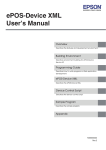
1.8.4.1 Class Diagram:
A class diagram describes the classes that make up a system and the static relationships
between them. Classes are defined in terms of their name, attributes (or data), and
behaviours(or methods). The static relationships are association, aggregation and inheritance.
The notation used in class diagram are as follows
ClientPass
Password
Inheritance
Class
Class Name
Attributes
byte[] result
byte[] buser
byte[] bpass
byte[] temp
+ Setcon()
+ Scramble()
+ Cleanup()
Methods
Flowcharts are the classical diagrammatic tool for designing either system or program logic.
They use symbols and interconnecting lines to show a system's overall work flow; showing
what is being carried out, logic and sequence of specific program operations.
Flowcharting is, however, more of a sequential approach. Activities are represented in a page
from top to the bottom and from left to right. There must be a start point and an end point.
Activities are commonly ordered in a determinable sequence.
1.8.5 Coding
The design will be converted into workable solution by using Java programming. Java byte
codes require a virtual machine to interpret them and execute the instructions natively. For
this new system I will be using Sun’s JDK 1.4.1 and the GUI design will be used based on
Swing components.
I have chosen to implement an “intelligence” to detect plagiarism. The book Constructing
“Intelligent agents with Java” provides a good introduction to some AI (artificial Intelligence)
concept and implementation.
My initial plan is to create a rule based reasoning system to analyse ASCII source files.
According to this, AI rule set will be configured to recognise java language and be able to
pick out plagiarism based on rules and this component should also be expandable to
5
accommodate other languages like C, JavaScript etc. This proves to be too daunting task to
be accomplished within the time frame that I have. So, instead of using rule-based method, I
have implemented a signature based method. Regular expressions are used to match patterns.
As of Jdk1.4.1, Java supports regular expression.
When creating application in Java, I have decided to use Swing components. This is to create
consistent look and feel, but also to take advantage of functionality more advanced than that
provided by native platform equivalents, such as AWT (Abstract Windows Toolkit). The
basic difference between Swing and AWT is that Swing is implemented with no native code
and therefore known as a “lightweight” component in contrast to “heavyweight” AWT native
platform component.
1.8.6 Testing
Testing any artefact of systems development, whether it is hardware or software, is always an
important activity however it is often squeezed to the end of a project. As I am aware of the
importance of testing the artefact from the very start of the project, I have decided to use the
approach of integrated testing throughout the software development process.
1.9 Technical Environment
Currently all Informatics centres are equipped with individual server. The server used in the
centre is a File server. A File server network is made up of Pc’s as well as a Server computer.
The server is usually responsible for the applications, and the information storage whereas the
Pc’s carry out most of the processing. The server uses Windows 2000 operating system and
all users Pc’s are running with Windows 98 operating system. All stand alone Pcs are loaded
with compilers such as Java Ski 1.4.1, C programming and Visual Basic 6.0. This server is
connected with all the labs in the particular centre. All labs have standalone PCs that are
connected to the server. All lecturers are equipped with Desktop Pc for their individual use.
Each centre has a student corner, which consists of few numbers of PC’s for student’s use.
1.9.1 New system requirement
My application Project manager is based on client server model. It will use java sockets for
network communication. The server portion will do the actual storing and maintaining of
student’s project files. The client GUI front end is based on Swing. It will allow students to
submit their projects and lecturers to view, grade, retrieve and analyse projects. By using
client server model, a single repository is possible.
6
2. Analysis
2.1 Introduction
The overall aim of the systems analysis section is to gain a thorough understanding of the
current system, the environment in which it operates in and to ascertain the future
requirements of the proposed system.
Although Yourdon (1989) argues that a great deal of time will be wasted modelling the
current system in detail (Bennet et al, 1999), the developers view on this stage of the project
is a mixed one. Whilst recognising that it is important to gain a clear understanding of the
problem domain and to elicit the users’ requirements as precisely as possible, it is also
recognised that this stage is one that could be possibly be iterative, as users’ needs and
options develop over time. However, given the developers recent history with the company in
question she feels that she already has a good insight into the current process and procedures
in place and as a result a considerable amount of time will be saved.
Aligning with the analysis phase of waterfall model, this requirements elicitation and analysis
process is an integral part of the lifecycle and will be addressed by the developer using some
of the more traditional methods, in order to maintain a clear understanding of the current
system and its environment.
Currently there is a manual system, more individual ways of doing things. The next part of
this analysis section will put the problem in context before going onto the requirements
determination process, determining what people do, how they do it and the volumes of works
involved. The existing system has then been modelled to gain a better understanding for the
flows of information before the section concludes with the full set of documented user
requirements.
2.2 Fact finding techniques used
A survey was conducted on the intended users to find out functional requirements of the
"Project Manager". Another purpose of the survey is to find out how I can re-engineer the
work process so that extra features can be produced when designing the software.
Questionnaires method was used as part of fact-finding procedures. Questionnaires were
completed by a total of 50 students and Lecturers. The Questionnaires were given to the
appropriate individuals to fill up. Specific set of questions was used in the Questionnaires.
Arrangement was made for the participant to complete the questionnaire.
2.3 Questionnaires
Questionnaires were distributed to 50 participating students and lecturers. Open and closed
questions were used.
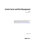
Questionnaire research design proceeds in an orderly and specific manner. Each item in the
flow chart depends upon the successful completion of all the previous items. Therefore, it is
important not to skip a single step. Notice that there are two feedback loops in the flow chart
to allow revisions to the methodology and the instruments.
7
Define Goals and Objectives
Design Methodology
Determine feasibility
Develop Instruments
Select Sample
Conduct Pilot Test
Revise Instruments
Conduct Research
Analyze Data
Prepare Report
2.3.1 Things to take note of when using Questionnaires
Too much often some people are using the questionnaire as a means to gather ideas. In doing
so, they hope to find clues which will enable them to go further down the road. Such a
perspective is a total loss of time and energy. It will never be repeated enough, if you do not
have any measure, the construction of the tool is premature.
8
Many researchers underestimate the time required to complete a research project. The
following form can be used as an initial checklist in developing time estimates. The best
advice is to be generous with your time estimates. Things always take longer than we think
they should.
Task
Hours Used
Goal Clarification
2
Overall Study design
2
Selecting Sample
N.A
Write the cover Letter
0.5
Conduct Pilot Test
1
Revise Questionnaire (If necessary)
0.5
Data Entry and verification
1.5
Coding open ended response
1
Analyzing data
1
Preparing the report
1
Printing and distribution of the report
1.5
Total Hours
12 Hours
2.3.2 Advantages of Questionnaire
Questionnaires are cost effective compared to face-to-face interviews. They are easy to
analyse. Data entry and tabulation can be easily done by computer software packages. It
reduces bias. There is uniform question presentation and no middleman bias. The researcher’s
own opinions will not influence the way respondents answer questions.
2.3.3 Disadvantages of questionnaires
The main disadvantage with a written questionnaire is the possibility of low response rate.
Sometimes it is simply not suitable for some people. The sample questions distributed to the
students and lecturers can be seen at Appendix 1.
2.4 Description of current system
In Informatics, student projects are submitted manually as a bound document with
accompanying floppy disks and a CDROM holding the source files. The following problems
are identified from the analysis phase.
A serious problem is in maintaining and handling the mass of student projects. For a class of
35 to 40 students, a lecturer will end up receiving a stack of project documentation. There is
difficulty in handling and keep track of projects. While space is one problem of the current
system, it is also difficult to keep track of who submitted what and when.
9
Each document comes with a floppy or a CD that contains the sources. Floppies are easily
damaged and not a reliable storage. Both floppies and CD-ROMs can also be misplaced.
If each project needs to be reviewed by a second marker, there will be the problem of
transporting the stacks of documentation to the reviewer.
As it is a modular based programme, it is possible for someone who has completed a module
to pass on a copy to his fellow classmate who has not done the module. There is nothing
wrong with such exchanges if proper recognition is given to the work of others. In fact such
exchanges of ideas and information could improve the overall academic standard. However
the problem arises when the student misuses it. Rather than using such material as references,
someone could possibly copy much of the materials and pass it off as his or her work.
The above points highlight some of the problems with the current system. My project will
attempt to build a Java based application that could offer a solution to some of the points
above. I call my application “Project Manager”. And henceforth all references to my
application will use this name.
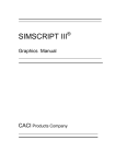
10
Acknowledg
ement
Hardcopy
project
Lecturer
C
it
bm
om
Su
m
en
ts
Student
pr
oj
t
ec
Results
Project Grade
Project Manager
Hardcopy
project
Hardcopy project
Final Grade
Comments
Moderator
Second
Marker
Project grade
Context data flow diagram- Fig 2.1
2.4.1 Requirements Catalogue & Data Dictionary
For the developer to begin the production of the final artefact, a comprehensive list of all the
data items, including structure, type, length etc. was required as well as a list of processes to
be carried out by the system. From reading around various development methodologies the
developer has sought to employ a variety of techniques to record this vital information.
As ongoing, almost running list, I have used the idea of the requirements catalogue, to record
requirements as they were identified, which as well as a textual description of the catalogue
entry will have a defined priority as well (Weaver et al, 1998) and can be seen in appendix 3.
The data items themselves have been documented and will be stored in the data dictionary
(Appendix 4), which has been carried by building on the concept of the Gane & Sarson style,
owing to the developers’ previous academic experience on the work of Garry Griffiths(1998).
2.4.2 New System Requirements
My application, Project Manager, is based on the client/server model. Currently one of our
online education Purpletrain using this technique. Purpletrain is purely an online education
system. The student is taught online and they will be submitting their project online. The
11
Purpletrain system can support the requirement of central repository for the new system
(project Manager).
The first option was to get the support from Purpletrain for the submission of taught course
project online. According to the management, as the Purpletrain operates worldwide and
currently the server is loaded heavily. And the management of Purpletrain is not ready to
support Project Manger.
The second option was to make use of the service of plagiserve.com. Plagiserve.com works
as follows. The student needs to register and become a member of plagiserve.com. It is
mandatory that the student needs to check for plagiarism by using Plagiserve.com and submit
the plagiarism report together with their final document. Based on the percentage-hit rate, the
student can be assessed. Here the responsibility goes to individual student. The problem with
this system is this service can detect the plagiarism for the information taken from Internet
only. This system is more suitable for research-based projects.
The requirements for the new system are client and server. All centres are equipped with a
servers and clients. The objective of the project is to create a prototype using Java. This
prototype includes an interface for student to submit their project and an interface for
lecturers to view and grade students' projects. Simple plagiarism identification is also
included in the server portion.
The system Project Manager is initiated due to increase in costs and the limitations of the
available system. In order to reduce the cost, management consider the option of replacing
the project manager with the current manual system.
Based on the findings above, it can be concluded that the school needs a better online
submission for projects. The students and the lecturers support this system unanimously.
2.5 Requirement Analysis
This section discusses tasks carried out during the analysis phase of the project. Analysis
defined by Hoffer et al as “ fundamentally an intelligent activity in which analysts capture
and structure information”. This information captured relates to the project domain and its
origins, objective of the process and current system utilised.
When performing analysis, information should be obtained from a wide range of sources to
maximise the analysts understanding. This concept was utilised when determining the
requirements for the project. Questionnaires were used to obtain information from various
sources.
The information gathered, identified that there were two different categories of user who
have dissimilar needs for the system and data.
Student Users
Lecturer Users
Once this information had been gathered, the next step was to structure it in a manner that is
unambiguous, concise and accessible to others (including non technical personnel) [Yeates et
al, 1994]. Structured techniques are typically produced to model existing processes, however
12
these can be extended to encompass models of the required system. Within this project
various techniques were used to document information following
Data Flow Diagram (DFDs)
Sequence Diagram
Process Tools
Data Dictionary
A mixture of tools was used, because each has their own strength and weaknesses.
DFD model both the flow of data and external information while sequence diagram provide
more detailed analysis of how external sources interact within the system. Following these
two stages, a set of requirements can be drawn up depicting the desired functionality of new
system. The following two subsections outline the main functional and non functional
requirements.
2.5.1 Functional requirements
Students will be able to:
1. login the system as a student with respective password;
2. identify themselves with their names and 12 digit ID and the lecturer name;
3. select the module for which they are submitting their project;
4. submit their project as a single folder. This folder can have any number of files;
5. get the confirmation that the project has been correctly submitted.
Lecturers will be able to:
6. login to the system as a lecturer with respective password.
7. view the lecturer screen
8. retrieve students’ projects for a particular module, term and year.
9. grade the project.
10. analyse the project for plagiarism.
11. receive comments for the particular project from the server.
Security
All users are required to log into the system with password.
Data store
A mechanism for bulk inputting user data must be provided.
2.5.2 Non Functional Requirement
All applications are stored in text files.
13
Upload time must be reasonable.
Information must be viewable for Lecturers.
The remainder of this chapter discusses the main considerations made during the design
phase of this project. Design is best described as implementing independent models to
represent information flows, how users interact with the system and how certain mechanism
will operate in a new system.
2.6 System Architecture
The system architecture used in this project is Client/Server based model. This project uses
communication mechanism linking some sub processes. The sub processes in this system are
User Interface
Processing Management
Storage Management
The client handles the Interface layer and the Server handles both processing and storage
management.
Informatics File Server
IBM Compatible
Hub
Student Workstation
Lecturer Workstation
14
2.7 Summary
This chapter has demonstrated to the readers the way in which the developer has gone about
eliciting the requirements from current manual system. By investigating the current practices
of the project manager has been able to learn in more detail what data and processes are in the
current system and what information needs to be stored in the new system. The list of
functional and non-functional requirements will now provide the input to the Design chapter,
which will look into how these requirements will be implemented into the new system.
15
3. Design
3.1 Introduction
Project Manager is built using Java, an Object Oriented language. I strive to build Project
Manager in an object oriented and modular way, so that each component can be updated and
changed independently of others.
My approach is slightly different from the normal system development life cycle. First, I
analyse the problems and come up with the solution (Project Manager) with the set of
features that I want it to have. Then I started building the application component by
component. Then I review my overall design and plan along the way.
I started small module, build up a component that works, then go on to the next and so on. At
each stage, I will plan how the components will tie in together and work as a whole. Some
rewriting of code may be necessary, but my design will be modular and component based.
Building component-by-component make a difficult task easier to understand and implement.
Since each component is tested along the way, the final test will not throw up too many bugs,
as most would have been eliminated earlier.
Once I have the entire application working, then I look at its overall design and do some
cleanup and optimisation, recoding components and modules if necessary. Reviewing the
design and recoding, will lead to more efficient and elegant design application.
As Project Manager is client/server based, a lot of trace information is needed. For each
component and class that I build, I have sprinkled System.out.println() to print out variables
etc. This allows me to trace the progress of the program and to debug errors. Such traces are
also useful in verifying that things are working the way that I intended. Some of them can be
removed for production version of application.
Design Layout
This section describes how the various classes are organised. At the top most level I have
organised all the classes under the same package, called Project Manager package.
Projectmanager class hierarchy
ProjectmanagerPackage
Server Classes
Common
Client Classes
Classes
16
The figure above illustrates the top-level design that consists of three sub groups namely
Server class, Common class and the Client class.
The server group mainly deals with the incoming client connections, they are also responsible
for carrying out the tasks that the client requests, keeping track of and maintaining the storage
of student projects. Another example is the configuration file, both the server and the client
uses the same configuration files.
The client file contains all GUI (Graphic User Interface) classes, the connection to the server,
and the instructions(protocol) to be sent to the server. Now we will move on to the details of
sub groups.
The following table shows the classes that are in the server group and a summary of what
they do. Detail of classes and methods can be referred at appendix 4.
3.1.1 Server Group
Class
Server
ServerThread Extends Thread
MyProtocol
Spassword extends Password
IDToken
ServerThreadFile
ServerGetProjects
Crawler extends Thread
Function
The main server class that starts the server
and listen for incoming client connections.
A new thread will handle each incoming
connections. This class is the ServerThread
that will start to handle a Client connection.
This class defines the six stages that each
single ServerThread can handle
This handles the password and userid
decryption and verification process.
The class that store a single authorization
token. This is make up of username and their
corresponding encrypted password.
The class that handles the incoming student
project files and details, storing these in
appropriate places. Also responsible for
creating the index file that allows the student
details to be found later.
Class to handle request student projects, it
will handle finding and sending the right
details and files to the client.
This class generates signature files for
module sources and comparing them to check
for plagiarism. It is a small AI engine.
17
The following diagram illustrates how the classes are related.
Server Class
ServerGetProjects
ServerThread
extends Thread
Crawler
MyProtocol
ServerThreadFile
SPassword
IDToken
18
3.1.2 Client Group
Class
MainClientWindow extends JFrame
MyMenuBar extends JMenuBar
ClientConnection
ClientPassword extends Password
LoginScreen extends JPanel
StudentScreen extends JPanel
SubmitServer
LecturerScreen extends JPanel
LectGetStudent
LectRetrieve
MyTableModel extends AbstractTableModel
Help extends JDialog
Function
This is the main class from which all the
other client GUI classes will be launched.
The class that implements the menu bar for
all our client GUI screen.
This is the class that provides the socket
connection to our server.
The client password class is responsible for
encrypting the userid and password.
The first GUI screen that user will see. It
contains field for userid and password.
This is the class for the student GUI screen,
this is where the student can submit their
projects.
This is the class used by the StudentScreen
class for submitting the projects to the server.
This id the class for lecturer GUI screen,
whether the lecturer can view, retrieve, and
analyse students projects.
This is the class will handle getting student
project details from the server.
This is the class that enables the setting of
grade and comments for a particular student.
Thus handles the data being shown by the
lecturer screen student project table.
The help class that displays help information.
19
Relationship of Client group
MainClientWindow
extends JFrame
Client
Connection
Help
LoginScreen
JPanel
StudentScreen
Jpanel
LectScreen
JPanel
MyMenuBar
JMenuBar
There are classes that are used both by Server and Client. The following table shows the
classes and their functions.
Class
ReadConfig
Password
StudentProject
Function
For parsing the configuration files of client
and server.
For providing the basic pass encryption
features.
A class for holding the details of a single
student project.
Besides these three main group of classes, I have also included a utility called
PasswordCreator. This is a java program that allows the creation of encrypted userid and
password file. This can be used to generate the serverpass.cfg file.
3.2 Input Specifications
The following table shows the input data that a student can enter at the student screen frontend.
20
3.2.1 Student Input Specifications
Field
StudentID
StudentName
LecturerName
ProjectTitle
ProjectSummary
Term
Module
ProjectFile
Project Sources
Format
12 numeric digits
Alphanumeric (no length limit)
Alphanumeric (no length limit)
Alphanumeric (no length limit)
Alphanumeric (no length limit) Generate examination
confirmation list
Standard selection (eg. Term1, term2, Term3,Tterm4.
Standard Selection that is fixed(eg.IT406—Java Programming,
IT413---Oracle)
A single project documentation file in Binary format(No size
limit).
All the source files in a source directory inclusive of all
directories relative to this base source directory.
3.2.2 Lecturer Input Specifications
Field
Format
Grade
Integer
Comments
Alphanumeric (Unlimited length)
An auto generated data field that cannot be amended is the date. It is stored internally as a
long type representing milliseconds since 1st Jan 1970.
3.3 File Specification
Project manager currently doesn’t use any database. It stores everything a plain text file and
uses the file system hierarchy provided by the operating system to manage all the text files.
Each module that a student take can have a total of seven data files. The following table
shows these files and their respective uses.
File Name
Uses/Explanation
Index.dat
The main index file containing the student id,
student name, lecturer name, Project Title,
Term, Module, Project file path, Project
filename, Source directory, submission date.
Each field is stored in a single line.
Summary.dat
Stores project summary.
Grade.dat
Stores the grade for this module as well as
many comments. The grade field is always
stored in the first line. All subsequent lines
are comments.
21
Grade.old
Backup file for our original grade file when
AI engine kicks in, it may modify the
comments in the grade file.
Crawler.dat
Unique signature file consists of multiple
lines that are extracted form the source files.
Ai.dat
Stores the number of Ai hits as a percentage.
tmp
A temporary working file used by AI engine.
In all these files, each unique field is stored in a single line in the order listed in the table. The
summary.dat contains multiple lines, but it stores only a single data field, project summary.
3.3.1 Configuration File Format
Besides these seven data files used to store information, Project Manager utilizes two
configuration files and a password file. The client portion (GUI front-end) of Project
Manager uses client.cfg as the default configuration file. The Server portion of Project
Manager uses Server.cfg as its default configuration file and it uses serverpass.cfg as the
password file where all the userids and passwords are stored.
The format of these files is simple. In client.cfg, there are two lines, host=127.0.0.1 and
port=5001. In server.cfg, there are port=5001 and path=C:\PMServer. The path specifies the
server data directory where all the student data are stored.
3.3.2 Configuration Files:
FileNme
Uses/Explanation
Client.cfg
Contains the client(GUI front-end)
configuration in name=value pairs.
Host =127.0.0.1.
Port=5001.
Server.cfg
Contains the server configuration
Example
PATH=G:\PMServer
Port=5001
Serverpass.cfg
Contains the username and their
corresponding passwords. The password is
encrypted and this entire file is written using
DataOutputStream treating everything as a
binary byte. MypassWordCreator.class
program is a utility that can be used to create
such files.
22
3.3.3 Index Files:
Addition to this, Project Manager also uses an index files to help it find and track the student
projects that are submitted. These index files are named index.dat. They exist in folders
named years like 2003. Within year folders there are further folders based on module names
like IT-406-JAVAPROGRAMMING, and within these module folders are the term folders
like TERM1, TERM2. Index files are located within term folders. Each index will simply
contain lines of studentids. The OS file system hierarchy is fully utilized by Project Manager
to enable it to track who has submitted in which year and term.
3.4 Program Validations and Processing
This section deals with some of the validation of user input done by the GUI front end as well
as how the password mechanism work and how the AI engine generates the signature files
and determines hits.
3.4.1 GUI validation and Security
As you see the input and file specifications, most of our user data has little or no restrictions
placed on them. This is possible because Swing components are being used. For this initial
release, my main is goal is to build a relatively secured program that can perform all the
features that I set earlier. Java itself is a secured language, the JVM checks for array out of
bounds and doesn’t allow buffer overflow or underflow. The result of this would be a run
time exception, which will halt the program before any damage occurs.
I am placing some faith on this mechanism to stop malicious input from users, for this 0.1
release. Subsequent releases could shift the weight of verifying to my own application code.
This is not to say that my current version doesn’t do any input checks. In fact it does some
very essential input validation.
Based on input specification, the studentid is limited to 12 digits. This is the single important
check to prevent malicious attempt that will overwrite critical system files or folders. My
program makes use of the OS file hierarchy system for storing of student data and details
rather than using a database. It is critical to prevent system path or filename to be entered
here.
The use of Swing components like Jcombo boxes which offers a selection list which helps to
prevent user from entering unwanted information. JfileChooser limits the user to select either
a file or directory. And for the Jtable that I used in the lecturer screen, the TableModel allows
me to specify the type of columns. Only two columns are set editable, all other columns are
simply for viewing only. The editable column is grade and comments. Grade column is
designed to have an integer object and the Jtable will be able to handle the check. And the
comment is String, so any editable characters can be entered. Again Jtable and Java handles
the checking.
This is one of the most useful features of Java language, the system takes care of many minor
details of programming, like memory sizing and data representation. However relying too
much on the language itself to handle checks will definitely impact security. I will highlight
the possible weakness of my program in later chapter.
23
3.5 Server Processing
For the server processing of project Manager, there will be a default data directory where all
the student projects will be stored. When the server starts up, it will read its configuration
file, getting the port number that it listens as well as the path for the data directory to use. If
the directory doesn’t exist it will be created. The default name that I use for this directory is
PMServer.
When a student submits project, a folder will be created for this student under the data
directory. The name of this student folder will be 12-digit studentid that the student has
entered. Hence it is very important for the front-end GUI to check this 12 digits input to
prevent malicious attempts to overwrite important system folders and files. Within this 12
digit student folder, a module folder will be created to store project that the student is
submitting.
Besides creating these data folders, the server also needs an index. So that again makes use of
the OS file hierarchy system., The Server would get the data and time which the project is
submitted. This date is actually entered when a student connects to the server. Hence the
student can’t cheat on the project submission date by modifying the system clock from which
PC he is submitting. When student submits a project, it would send the time back to the user.
The server would extract 4-digit year from this timestamp and use it to create a year folder
under the top-level data folder. Then it would create a module folder under this year folder
based on the module for which the student is submitting. Within the module folder, a Term
folder would be created based on the Term the student has selected. Within this Term folder,
there would be an index file called index.dat. This will holds the information such as
studentid, module, Term and year. This allows the server to keep track of the time and date
on which the student submits the project.
The actual project details are stored in the module folder of the particular student folder. The
index.dat file in this module folder contains the various fields, which the student has entered
during project submission.
I understand it sounds a bit confusing. Please do not confuse between the student index file
and server index file. The student index file simply stores students project details for the
module the student has submitted project. The server for finding and locating student projects
uses the server index file. The server would also create grade file that stores the grade and
comments that the lecturer has sent. It will be in the same folder as the student’s index file.
An example would be
[BaseServerDataFolder] \ [StudentId] \ [ModuleName] \
index.dat
and
[BaseServerDataFolder] \ [StudentId] \ [ModuleName] \
grade.dat
I hope this sums up how the OS file system hierarchy is used.
24
3.6 Password Encryption Scheme
The userid and password encryption scheme that I used can be broken down into two
sections. One is the secured storage of userid and password file. Second is the transmission of
secured userid and password through network. The linux and Unix System influences the first
section. The second is influenced by Yahoo.com.
3.6.1 Password and userid File Storage
In Linux, the userid and password are stored in /etc/password file. These files are secured and
only can be read and written by the root user. Modern Linux and Unix offers additional
password protection scheme called “Shadow Password” Which I am not going to go in detail.
In the /etc/password file, the userid is plainly visible, but the password is encrypted. This is
what I would do for my password file. Also the server should be running in an operating
system that offers file and directory level security. This will allow access permissions to be
set on the server password file, providing added security. But for demonstration purpose,
Windows 98/95 would be sufficient. Here I have chosen Message Digest 5 as the encryption
mechanism for passwords.
Message digest 5 simply processes an input stream of bytes (can be text or binary) and
generates a unique 16-byte signature (digest) for the given input. It is believed that there are
no two inputs with the same digest (much like our finger prints, no two human having the
same prints). Another characteristics md5 is that given a digest, it is not possible to know
what input generated the digest. The meaning of this is we can’t reverse the md5 process on a
given digest and get the input. MD5 is one way hashing code.
This enables it to encrypt a given text or password and generate unique digest that can’t be
reversed back to the original text or password. So only the original user knows what
password it is. MD5 is widely used in the open source community as a checksum for the
source files and binary packages that are distributed.
Java 1.4 has a security package, Java.Security which contains a message digest class that
implements MD5. I am using this message digest class, request a provider for MD5 and then
uses the requested MD5 object to do encryption.
For userid and password storage, they are stored as binary bytes using a DataOutputStream.
The format is user=encryptedpassword. One such entry per line. I have written a Java utility,
MyPasswordCreator which can create such a password file.
The password portion will be of gibberish of characters. The plain text password is first
encrypted with MD5 to generate a first digest. This first digest (16 bytes) is then appended to
username and MD5 encrypts the resulting bytes again. This final output is stored as password
portion.
3.6.2 Password and userid transmission
This section deals with the transmission of userid and password through the network. Project
manager is a client/Server model and the information need to travel through a network, which
is inherent.
For demonstration, I am going to use a stand alone PC. I can simply use the local loop-back
and run both the server and client locally. They still communicate through sockets, like what
they will do across an actual network. It uses socket locally as well as within a network for
graphical display.
25
Yahoo.com influenced my userid and password mechanism. Normally when log into Yahoo
account, Yahoo uses a JavaScript MD5 implementation to encrypt password before sending it
through the network. No plain text transmission is allowed. I came to know about this
mechanism when I was teaching the module html and JavaScript (WL1)
Yahoo did not create the JavaScript MD5 implementation, rather it was written by a British
youth who made his script available (WL2).
The yahoo server will generate a random number and embed it within the password form at
its login page when a user requests for a page via a browser. After the user keyed in his id
and password, and hit the submit button, several things happen. Firstly, there will be a
browser compatibility check. If this passes, then the JavaScript MD5 is invoked. It will take
the password and message digest to generate 16 bytes digest. This digest joined to the random
number and generate new digest.
This is the first level of security, no hackers will be able to infer the password from the digest
unless they have limitless computing power at their disposal to try a brute force cracking.
I did it slightly different way from the Yahoo model. But basically the idea is the same. The
following code taken from ClientPass shows the encryption process.
result = Encrypt(bpass);
temp = merge(buser, result);
result = Encrypt(temp);
temp = merge(result, getRandbyte());
result = Encrypt (temp);
result is a byte array that will be the final digest sent across the network, buser is a byte array
contains username or userid, bpass is the byte array contains the password. GetRandbyte will
retrieve an array of 64 bytes of random data. Merge is a join method for joining two byte
arrays together to give a single byte array. The password is encrypted first and joined to the
username and they are encrypted and this is joined to the random bytes and encrypted to give
the final digest. This far more secured than the yahoo.com method as the username, just a
stream of bytes that is different each time.
Crawler and AI engine
Plagiarism, what does it mean exactly. Here is the definition.
The act of taking the writings of another person and passing them of as one’s own. The
fraudulence is closely related to forgery and piracy – practices generally in violation of
copyright laws.
The above definition applies to writings and violations of copyright, what about software
sources, are these considered writings? They are definitely a form of expression and protected
by copyright laws. The software sources can also be plagiarized.
26
In software there is a saying “ why reinvent the wheel”, the actual meaning of this is code
reusability. When we look at stdlib that we are using today, we all use scanf(), printf() etc.
This is use of other’s work. But it is not plagiarism. Object Oriented language provides a
greater challenge, there are many prebuilt classes and libraries, with much data and code
abstraction, indeed it is very difficult to identify which is original. In education and teaching,
it could even be harder. Normally how the students copy code? The stupidest method is just
to simply grab all the sources without modifications and call it their own. A more intelligent
approach is to get source, and modify some of the parameters like the text message, data and
some information to suite their purpose. The above two methods does not require much
knowledge about programming language. So if we strip away the white spaces, strip away the
parameters, data and comments, the digest of this would be the same as original.
The difficulty is when the copier knows the programming language and is able to modify not
just parameters but also methods and classes. Here comes our AI engine. Now we will how it
works.
In Java, package is also related to directory, and class can be related to file names. For
example if the class contain a method that has the same name as another method in some
other class of other student. In some other cases no same method, but parameters are the
same. It indicates a strong possibility of copying.
The class, which is used to find such similarities, is Crawler. It search all the different folders
of each student, looking at the sources and generating a signature file called crawler.dat. To
make it simple, I took only class and method signature. I have used two patterns for
matching, one for class and the other for method. The code snippets is from Crawler class
and shows the regular expressions patterns for the class and method.
private String classpat = "class\\s+([a-zA-Z0-9]+)\\s"; //pattern for class
private String method ="([_a-zA-Z\\$]+[_a-zA-Z0-9\\$]*)\\s*\\(.*\\)\\s*\\{"; //pattern for
method
The pattern for searching for class is any string that contains the word “class” followed by at
least one white space or more and then any alphanumeric characters one or more times. I
found that this pattern allows to pick up classes easily.
Next is pattern for matching method. Any alphabets, underscore, dollar sign followed by any
alphanumeric or underscore or dollar sign zero or more times followed by a white space zero
or more times followed by an open bracket”(“ and any characters in between followed by
closed bracket”)”, followed by a white space zero or more times, followed by curly bracket
“{“.
While the first class pattern is able to pick up classes nicely, but this second pattern for
method doesn’t pick up method as clean as class. The reason is things like (IOException e) {,
while(true) }, System.out.println(“Kdofa{, etc.. do appear sometimes. However since I am
using both patterns together, class match followed by method match forms a single line , but
as an example I have included some from each class to give a mini view or what Crawler.dat
is really about.
27
PassWordCreator.java
Class
PassWordCreator
PassWordCreator.java
Class
to
PassWordCreator.java
Method PassWordCreator
PassWordCreator.java
Method catch
PassWordCreator.java Method catch
MyTableModel.java Class MyTableModel
MyTableModel.java Method
MyTableModel
MyTableModel.java Method
MyTableModel
MyTableModel.java Method
for
MyTableModel.java Method
getColumnCount
MyTableModel.java Method
getRowCount
MyTableModel.java Method
getColumnName
StudentScreen.java Class StudAction
StudentScreen.java Method
StudentScreen
StudentScreen.java Method
actionPerformed
StudentScreen.java Method
if
StudentScreen.java Method
if
SubmitServer.java
Method
submitsourcefile
SubmitServer.java
Method
for
SubmitServer.java
Method
resetcon
SubmitServer.java
Method
submitprojectfile
SubmitServer.java
Method
for
SubmitServer.java
Method
sendBinFile
SubmitServer.java
Method
while
SubmitServer.java
Method
if
SubmitServer.java
Method
while
SubmitServer.java
Method
LecturerScreen.java Method
browseSave
LecturerScreen.java Method
if
LecturerScreen.java Method
showWarning
LecturerScreen.java Method
valueChanged
LecturerScreen.java Method
if
This is the unique signature of some sources of project manager. It is highly unlikely that
someone else could have the same exact signature file unless they copy project manager
sources exactly.
After crawler crawls through all the source directories generating crawler.dat for each set of
students sources, it will then start comparing crawler.dat files that belongs to the same
module. In this case, it will compare Project Manager signature file with other signature files
from other projects in Java Programming module. In this way it detects hits (similar lines).
Suppose we have a crawler.dat A, and second crawler file B, The first line of A is read and it
is compared to all the lines in B. Once it finds a match, a counter is incremented and the
second line of A is read. This process is repeated until all the line in A has been compared.
The counter would hold the number of hits. This value divide by the total number of lines in
A will yield the percentage of A’s signature that is similar with B’s. The percentage result is
stored in ai.dat and also uploaded into grade.dat. Furthermore, the directory string of B will
28
be stored into the comments of grade.dat. This allows the lecturer to know both the
percentage of similarity as well as with whom it is similar.
How well does this heuristic work? Frankly I don’t really know. It takes lot of testing with
the large sample of diverse sources before knowing the result. I find it works moderately
well. For blatant and outright copying, this method should be able to pick them out easily.
29
4. Coding and Testing
4.1 Coding
As I have stated in my Introduction, I have done the coding by using Java Jdk 1.4.1. The
main reason for using Java is I am more familiar and comfortable with Java other than any
other language. And also I was able to integrate AI with Java. I have done the Design and
coding concurrently. The language is chosen based on the following characteristics.
Ease of design to code translation
Compiler efficiency
Source code portability
Maintainability.
Although there are many “new and better programming languages, sometimes it could also be
better to choose a “weaker” (old) language that has solid documentation and support
software, is familiar to everyone on the software development team and has been successfully
applied in the past. It is true in my case since I have done a small project on Java for my
CSM1020 module that gave me the confidence to use Java.
4.2 Testing
Testing the artefact of systems development, whether it is hardware or software, is always an
important activity, however it is often squeezed to the end of the project due to the enforced
pressures of time upon a project (Cheffey et al, 2003). It is a renowned fact that no system is
built without containing few bugs but if the identification of these errors goes unnoticed then
the chances of successful project will have been severely hindered (Jordan et al, 1990).
As I am aware of the importance of testing the artefact from the very start of the project and
one of the main reasons for adapting the Life Cycle Model approach. Owing to previous
development experience whilst working for small project, I am very much accustomed to the
approach of integrated testing throughout the software development process. In addition to
my experience, the principle of the adapted methodology states that testing should be
integrated throughout the development life cycle.
Bearing this point in mind, the majority of the testing has been already carried out in the
iterative design and build phase of the project. When writing each class and method, the
developer tested to see that the correct results were being obtained. For example the class
used to detect plagiarism and write the comment into grade.dat was tested to ensure that the
similarities are detected and it is saved into grade.dat.
Having stated that the majority of testing has already been accomplished by integrating it
throughout the life cycle, there is still some final testing to be carried out. By looking at the
V-Model for systems development (figure –source: Adapted from Life Cycle Models, Allan
2003b), it can be seen that having adopted the integrated testing approach the developer has
30
already considered the majority of testing that takes place within the system, with the
exception of User Acceptance Testing.
User
User
Acceptance
Requirement
System Design
System Testing
Program
Program
Design
Testing
Code
The final stage of user acceptance testing is where the final artefact is tested in the operating
environment where it will eventually be used (Hoffer et al, 2002). Owing to the fact that the
users were involved throughout the development, the developer had already been testing the
artefact using simulated test data(Alpha testing) and was confident that the system was
producing the correct and desired results. So the final stage is to employ Beta testing
strategy, where the members of Project Manger used the system in their working
environment.
For testing I have used AMD K6 III 500Mhz pc running Windows 98 second edition.
Although my main testing was using Windows 98, Project Manager should also be able to
run effectively under Linux or Unix. In fact project Manager should be able to run pretty
much the same on any machines that supports the Sun JRE 1.4.
31
Test Case
Test Plan
1.
Test That the Server is able to read its configuration
server.cfg properly
2.
Test that the client is able to read its configuration file
client.cfg properly
3.
Test that the userid and password are sent as a different
random stream of bytes for each connection.
4.
Test that when wrong userid and password is entered, the
login screen will prompt the user and exits.
5.
Test that when the correct userid and password is entered,
the student can proceed to the student screen
6.
Test that when the correct lecturer id
and password is entered, the lecturer can proceed to the
lecturer screen.
7.
Test that the Exit on the menu bar is working.
8.
Test that the help on the menu bar is working.
9.
Test that the about on the menu bar is working.
10.
Student screen: Test that when essential fields are not
filled in, a error prompt will come up.
11.
Student Screen: Test that when a student enters illegal
characters for StudentID, a error prompt will come up.
12.
Student Screen: Test that when the student selects the term
and module, the right data is sent to the Server.
13.
Student Screen: Check that when the student clicks on the
browse source directory button, the JFileChooser dialog
for selecting directory will pop up.
14.
Student Screen: Check that when a student clicks on the
browse project documentation button, The JfileChooser
for selecting a single file will come up.
15
Student Screen: Check that when the submit button is
clicked, the project details source files and documentation
will be sent to the Server.
16.
Student Screen: test that after submission, a dialog box
will pop up saying that submission is successful.
17.
Student Screen: Test that when the reset button is clicked,
all the fields will be emptied.
18.
Lecturer screen: When the lecturer clicks on update, the
32
application will fetch the project details from the server
and update the JTable.
19.
Lecturer Screen: Test to prompt a message when there is
no match of the selected criteria.
20.
Lecturer screen: Test that the JfileChooser will pop up
with the message asking for a place to store the student
projects when a lecturer selects a particular project to be
retrieved.
21.
Lecturer Screen: Test that the lecturer can edit the grade
column and the comments.
22.
Lecturer Screen: Test that when the Lecturer click on the
set grade button, the student's grade will be updated on the
server.
23.
Test that when the Lecturer clicks on the analyse button,
AI crawler is started on the Server
24.
Lecturer Screen: Test that a pop up message will be
appeared saying to wait and also informs that only one
analysis can be made per session.
25.
Lecturer Screen: After analysis, when the lecturer clicks
on update again, the comments column will show the
analysis result.
The main test cases are shown below. The detailed test cases can be referred appendix 7.
33
Login Screen
34
Student Screen
35
Lecturer Screen
36
Student’s project submission
37
Lecturer View project
38
Once Analyse button is pressed
39
View comments
The comments stated 1.0 means it is of 100% similar code. As I have uploaded the same
source code for the user Viggi and Raji, it is able to detect the similarities.
40
The user John’s code is 10% similar to Viggi, as the developer discussed in the earlier section
up to 20% of similarities are acceptable because of code reusability.
The result from the Beta Test scenario were extremely positive (appendix 7), although there
were some recommendations and system imperfections reported. Every member of the
Project Manager was able to log into the system and able to upload their project.
A negative aspect that came back from the beta testing was that as the number of student
increases, it was taking longer time to do the search. For one student approximately it takes
30 seconds to do a search. For a class of 40 students it may take more than an hour. But it is
worth spending one hour to detect the similarity of coding. Although the volumes of projects
this was something I have considered when designing the system, it was not anticipated that
the search would take so long to display results and it is an unfortunate drawback. Still it is
much better than the manual search.
41
5. Evaluation and conclusions
5.1 System Evaluation
This chapter of the report looks into the overall success of the project Manager that has been
developed for the submission of projects. To prove the overall success of the final system, the
developer has utilized two different evaluation methods, which were
• to evaluate the system against the user requirements, and
• to evaluate the system against the system previously used.
5.1.1 Evaluation against Requirements Specification
From the system analysis that has previously been carried out (Chapter 2) the developer has
indicated a list of user requirements that were the required functionality for the new system.
To judge whether or not the developer has attained these targets each of the requirements has
been evaluated and discussed.
To provide a single repository to hold project submission
The main purpose of this project was to solve the problem of manual storage of projects and
to keep track of the students who have submitted their projects, which have been achieved by
the developer. By adopting client/server architecture, students are able to submit their project
as softcopy.
A GUI front end to enable student to submit projects
The system was not only required with central repository, but also to provide good user
Interface. This requirement was achieved by creating a central interface on the main
application window that showed the login screen. Its main difficulty lies in the fact that the
developer comes from a technical background and has little practical experience in dealing
with Java environments. Although Java is one of the module in M.Sc course, GUI concept is
totally new to the developer and substantial time has been spent on understanding the
concepts.
Access Control facilities to prevent unauthorized access
Following on the previous requirement, this next item of functionality was also achieved.
Currently, the default accounts are set as follows
Default Login for Student is username: Student password: password
Default Login for Lecturer is username: Lecturer password: password
By using password creator utility the default password could be changed to any password.
But the user name should be Student or Lecturer.
A mini AI engine that allows the system to warn the lecturers of possible plagiarism.
Based on the hit rate the lecturer could conclude the possible plagiarism. For lower figures
like 10 to 20 %, it should be reasonable. This is because of the way the AI engine works. As
explained in the previous section, the crawler.dat signature could have some common lines
such as try { }, catch{} etc.
Non-Functional requirements
Every non-functional requirement that was set in the requirements specification was achieved
in the final system. As per requirement, the upload time was reasonable and information was
viewable by Lecturers.
42
From the beta testing that was carried out after the system has been installed, each member of
the team agreed that the system was simple and quick to use. The only drawback was the time
taken to analyse the projects when the number of project is increased. It allows the lecturer to
keep track of the information such as name, id, submission date etc. All the information was
stored in a text file, which was created under different userid.
5.1.2 Evaluation against Original System
The original system, or the manual system, that were used to manage project submission, fall
a long way short of meeting any of the functionality that is offered by the new system.
The greatest problem with the way in which submission was previously managed was the
lack of standardized and centralized approach. In a manual system, all lecturers worked
independently and in an unstructured way. The new system that has been developed solves all
problems and drawbacks with the previous system and has been built in a scalable fashion for
any future enhancement.
5.2 Known bugs and issues not resolved in this release
As we know, no software is perfect and any user manual would be incomplete without
warning about the current known bugs and unsolved issues. I shall highlight few possible
bugs and security loopholes.
Multiple submissions of projects: when a student submits a project multiple times, the
lecturer screen will show multiple rows of the same student. However, when the lecturer
retrieves only the latest file would be retrieved.
Overwriting other students project: A malicious student could easily overwrite another
students project if he or she knows the student id. This is a major security loophole, which
needs to be solved for any real system.
For this release my goal was to demonstrate a working prototype with all the features I have
stated.
5.3 Strengths and weaknesses of the system
5.3.1 Strengths
By using a Client/Server model, Project manager allows a centralized method of organizing
and storing student projects. Another advantage of the system is password encryption
scheme. Rather than hard coding userids and password into the program code, a separate
password file is used. And the passwords in this file were encrypted.
The use of configuration file for both client and server is another strength of project manager.
Finally, Project Manger is designed as modular base. For instance, the student screen
functions could be changed without affecting the lecturer screen. Such modular design allows
parts to be changed easily and new features to be added. It is also easy to debug and maintain.
5.3.2 Weaknesses
As highlighted earlier, the bugs identified in the previous section can definitely be considered
as weakness of Project Manager. The other aspects of Project Manager is, when I strive to
build a component based and an Object Oriented design that can enable code reusability, the
developer admits that some parts of the coding were really quick hacks to get the application
going.
43
Furthermore the communication protocol between the server and the client was delicate and it
was not perfect in some places. Better planning and clean separation of communication
protocol from the components would provide a better design. Project Manager utilizes the
Operating System hierarchy to organize and store student’s projects instead of using a
database. The weakness is that there is no concurrency protection in this release. Also there
were insufficient checks for user identity.
5.4 The development method
It would have been better to use Visual Basic than Java and instead of using text files for
storage to have used database. Although the back end is non-transparent to the users, it could
have been easier to manage and control data if it were database oriented. But the Visual Basic
is very much new to me and the developer I am familiar with Java and was able to achieve
the required specification.
As I have stated earlier, each centre has its own server for storage. Currently, the system was
implemented in one centre as Pilot approach. If it is successful then it will be implemented in
the remaining centres. Meanwhile the bugs and security loopholes will be rectified before the
release of second version
44
References
1. AVISON, D AND FITZGERALD, G. (2003). Information Systems Development:
Methodologies, Techniques and Tools. 3rd ed. McGraw Hill.
2. BENNETT, S, MCROBB, S. and FARMER, R(1999). Object Oriented Systems Analysis
and Design using UML. McGraw Hill.
3. BRUCE ECKEL Thinking in Java 2 http://www.mindview.net/Books
4. CHEFFEY, D., BOCIJ, P., GREASLEY, A. and HICKIE, S. (2003). Business Information
Systems: Technology, Development and Management for the e-business. 2nd ed.Prentice Hall.
5. DON YEATES, JAMES GDLE, MAURA SHIELDS, DAVID HELMY. System Analysis
and Design. Prentice Hall, 1994.
6. GRIFFITHS, G. (1998). The essence of structured Systems Analysis Techniques. Prentice
Hall.
7. HOFFER, J. A., GEORGE, J.F. and VALACICH, J.S.(2002). Modern System Analysis
&Design. 3rd ed. Prentice Hall.
8. IVOR HORTON, (2000). Beginning Java 2 . Work Press
9. JOSEPH P.BIGUS and JENNIFER BIGUS (2001). Constructing intelligent agents with
Java
10. PRESSMAN, R.S(2000). Software Engineering A practitioners approach. 5th ed McGraw
Hill
11. WEAVER, P.L., LAMBROU, N. and WALKLEY M. (1998). Practical SSADM Version
4+ - A complete Tutorial guide. 2nd ed. Pitman Publishing.
Web References
www.pajhome.org.uk/crypt/md5- Concepts in encryption
http://www-106.ibm.com/developerworks/java - Java Socket programming
www.javasoft.com- Official Sun Microsystems Java Site.
45
Appendix
Appendix1 – Sample Questions
Questionnaires Form
Name: ___________________
Class: ___________________
Date: ___________________
Questionnaires (Lecturers only)
1. How would Not Good
you grade your
IT
skills?
(Software)
Can Do
Good
Very Good
2. Do you find Very Taxing Taxing
current Project
submission
system taxing?
O.k.
No
What do you Nothing
dislike
most
about the current
system?
Time
consuming
Problem to Conflict
keep track of results
the project
Not
How
comfortable are comfortable
you about the
new idea of
online
submission?
O.K
Would
to try
Are
you NO
prepared to have
online
Submission
system?
Maybe
Would Like Yes,
to try
Definitely
What
features Central
would you like Repository
to have in the
new system?
Check for Both
plagiarism
in
like Very
comfortable
Nothing
Please put you thoughts on having online Project submission system
46
Questionnaire (Students)
1. How do Not Good
you
grade
your IT skill?
Can do
Good
Very Good
2. Will you Not
Comfortable
feel
comfortable
to
have
online project
submission
system
O.K
Would like to Yes,
try
Definitely
Plagiarism
What
check
features
would
you
like to have
in the new
system
Central
repository
Both
Nothing
47
Appendix 2
Design Tools considered
2.1 Logic flow chart
Flow charts are no longer considered as modern technology. Flow charts focus mostly on
decisions, a special type of process that now appears in DFD and object diagrams. A
summary of flow charting technique is as follows.
1. Functions, or processes are represented by rectangles.
2. Decisions are represented by diamonds
3. Inputs are represented by parallelograms
4. Outputs are represented by a hardcopy symbol ( a rectangle symbol with a wavy
bottom edge).
2.2 Nassi-Sceneiderman Diagram
It is a modern alternative to flow charts.
1. Can be drawn using text and line.
2. Shows process by series, by selection or iteration
3. More structured than flow charting
2.3 E-R Diagram
It is used to model the entities that a computer system records information about, and the
relationships between those entities. The evolution of ERD typically progresses either from
scratch or it is reverse engineered from existing database schema. It supports various stages
of development, beginning with support various stages of development, beginning with a user
readable form that allows validation of design, and is used by developers to validate a design
at summary levels.
Many developers and CASE tools still use Bachman’s crowfoot notation to indicate the
cardinality of relationship. The relationship type is written on or near the line that represents a
relationship.
2.4 Data Flow Diagram
DFD assists in the functional decomposition process. There are different notations and
standards are available. For my project, I am using Yourdon notation and standard.
The attributes of Yourdon notation is as follows
1. Two parallel, horizontal lines represent a data store.
2. Processes are represented by a circle
3. Rectangular or square boxes to represent Input.
4. Directed arrow to represent data flow.
48
Acknowledg
ement
Hardcopy
project
Lecturer
C
it
bm
om
Su
m
en
ts
Student
pr
oj
t
ec
Results
Project Grade
Project Manager
Hardcopy
project
Hardcopy project
Final Grade
Moderator
Comments
Second
Marker
Project grade
Level0 DFD
49
Project
Student
Submit
project
Final Grade
View and
grade
Exam division
Compare
and
grade
Moderator
Hardcopy store
First marker
Second
Marker
New Store
View and
grade
Level1 DFD
50
Appendix 3
Requirement Catalogue
ID
Description
01
Getting connected to Server
02
Getting acknowledgement from Server
03
Password checking
04
Create login Screen for Student and Lecturer
05
Allow submission of projects for students
06
Validate all field
07
Getting acknowledgement for project
submission
08
Validate Reset Field
09
Allow Lecturer to view projects
10
Validation on Lecturer Screen
11
Allow Lecturer to edit grade
12
Allow Lecturer to analyze the projects
13
Pop up screen to indicate analyze is complete
14
Allow Lecturer to update the status
51
Appendix 4
Data Dictionary
4.1 Student Input Specifications
Field
Student ID
StudentName
LecturerName
ProjectTitle
ProjectSummar
y
Term
Module
ProjectFile
Format
AlphaNumeric
Alphanumeric(no length limit)
Alphanumeric(no length limit)
Alphanumeric(no length limit)
Alphanumeric(no length limit)Generate examination confirmation list
Standard selection (eg. Term1, term2, Term3,Tterm4.
Standard Selection that is fixed(eg.IT406—Java Programming, IT413---Oracle)
A single project documentation file in Binary format(No size limit).
All the source files in a source directory inclusive of all directories relative to this ba
Project Sources directory.
4.2 Lecturer Input Specifications
Field
Grade
Comments
Format
Integer
Alphanumeric (Unlimited length)
52
Appendix 5
Class Diagram
ClientConnection
-ClientSock
-hostname
-port
-in
-out
+ Client Connection ()
+ Send ()
+ Receive ()
+ Reset ()
+ Cleanup ()
+ Finalize ()
clientConnection class to enable the client to get a socket to link to the server
53
Lect Get Student
- Module
- Term
- Year
- Array[]
+ Update Student Tables()
+ Get Student Objects ()
LectGetStudent class to handle the connection between the Lecturer and the Server
Gets the student details from the server
Lect Retrieve
- Client Connection
- Save Dir
- Std
+ Retrieve ()
LectRetrieve class to handle retrieving the project files belonging to a student project
from the server to the client
54
My Protocol
- Start
- Pass
- Date
- Send Project
- Request Project
- Analyze
- Quit
- State
- Security Clear
+ Response ()
+ Set Security Clear ()
MyProtocol class to handle the protocol states between the Client and Server
55
Read Config
- Host
- Port
+ Read Config ()
+ Read File ()
+ Parse Key ()
+ Get Host ()
ReadConfig class to read the configuration files for server
and client
56
Lect Set Grade
- Client Connection
- Student Project
+ Set Grade
LectSetGrade class to set the student grade
Password
- Username
- Password
- Digest
- Random
+ Password ()
+ Encrypt ()
+ Merge Array ()
+ Finalize ()
+ Trace ()
Our top level password class , password and username will be protected through the use
of message digest 5 . It will be provided by the java.security package
Server
- Port
- Server Socket
- Server Config File
- Read Config
- Path
+ Server Init()
+ Listen ()
+ Finalize ()
Main server class used for listening for incoming connection
Server Get Projects
- Year
- Term
- Module
- Path
- Input
- Output
- My Array
- Compare
57
+ Unit Request ()
+Set Grade ()
+ Send Proj File ()
+ Construct Rel Path ()
+ Send Student Objs ()
+ Find Project ()
+ Construct Stud Objs ()
+ Read Student File ()
ServerGetProjects class to handle request for incoming student projects.
This single server class will handle all request for student projects.
Its client counterparts are LectRetrieve class , client class which handles the client
retrievingof files from server , LectSetGrade class ,client class which handles the client
setting of grade, LectGetStudent class, client class which handles the getting of student
details to be display on client JTable from server.
StudentProject
- StudentId
- StudentName
- Lecturer
- ProjectTitle
- Term
- Module
- Year
- Grade
- Comments
- submittedDate
+ setStudentid()
+ setStudentName()
+ toString()
class to hold information for each student project
SubmitServer
- StudentName
- StudentId
- Lecturer
- ProjectTitle
- ProjectSummary
- Term
- Module
- CurDate
- ProjectFilePath
58
-
SourceDirectory
Connection
PassHandler
+ getSourceBaseDirectory()
+ getSourceDirectory()
+ resetcon()
+ submitProjFile()
+senBinFile()
class that handles the submitting of project from studentscreen to the server
Password Relationship
Security
Password
ClientPass
ClientPass
- byte[] result
- byte[] buser
- byte[] bpass
- byte[] temp
- Random ranobj
+ Setcon()
+ Scramble()
+ Cleanup()
ClientPass class to handle password authentication with the server
it extends our base Password class
59
Thread
Crawler
ServerThread
60
Crawler
- String PATH
- String classpat
- Vector myvect
- Pattern mthp
- Pattern classp
- crawlFile = new Vector()
- private int crawlcnt
+ run()
+ buildCrawl()
+ getCrawlResults()
+ compareCrawl()
+ crawlWriteResults()
This is our ai class , called crawler to actually search through our server data
directory. It will find all student folders , and go into each modules folder in each
student folder analyse the source files found in the source folder in each module folder
and generate a unique signature for each module. Then it will compare such signature
files in an attempt to determine
whether there is any plaigarism . The result will be written to ai.dat and grade.dat
Server Thread File
- My Plan
- Check
- Mod
- Path
- Src
+ Get Project Details ()
+ write Main Server Index ()
+ Get source File ()
+ Create Src Dir ()
+ Write Project Index File ()
+ Get Project Document ()
+ Initial ()
+ Write Project ()
our individual thread server classes that will be handling each incoming client
connections. Each incoming client connection will be assigned a single thread that will
handle it.
61
Table
AbstractTableModel
MyTableModel
MyTableModel
- boolean DEBUG=false;
- final String[] columnNames
+ getColumnCount()
+ getColumnName()
+ isCellEditable()
+ printDebugData()
TableModel class to format all the student details that appear
in the
JTAble. This class is based upon the sample provided by the Sun Java Tutorial. I have
built upon and expanded on it so that it can handle my student objects for
ProjectManager.
Swing
Jdialog
Jpanel
JMenuBar
Help
MyMenuBar
LecturerScreen
LoginScreen
JFrame
MainClientWindow
62
LectScreen
- MainClientWindow win
- ClientConnection con
- ClientPass passhandler
- GridBagConstraints constraints
- GridBagLayout gb
- JTable mytable
- JTextArea mytextarea
- JComboBox cterm , cmodule , cyear
- JButton bupdate , bretrieve , banalyse ,
bsetgrade
- LectAct myact
- myTableListener tableact
- StudentProject[] mystd
- File savedir
- int mySelectrow = -1
- String year
- String term
- String module
+ setStudentGrade(0
+ browseSave(0
+ valueChanged()
+ buildHeading()
+ getDate()
+ buildTop()
+ buildMiddle()
+ buildBottom()
This class creates the Graphic User Interface for the user.
LoginScreen
- MainClientWindow win
- ClientConnection con
- ClientPass passhandler
- JPasswordField passfield
- JTextField userfield
- JButton blogin , bexit
- byte[] password
- String username
- Box ubox, pbox , bbox
+ getPassword()
+ Scramble()
LoginScreen for the user to enter password
63
MainClientWindow
- MyMenuBar mymbar
- ClientConnection con
- LoginScreen mylogin
+ WindowClosing()
+ dispose()
+ cleanup()
MainClient Screen to launch the client GUI
MyMenuBar
- JMenu fmenu ;
- JMenu hmenu ;
- ClientConnection con;
- MainClientWindow win;
+ buildMenu()
+ showAbout()
+ showHelp()
MyMenuBar Class to build the GUI menubar
64
Appendix 6
Sample code
/** clientConnection class to enable the client to get a socket to link to the server
ProjectManager
copyright Raji nov 2003
*/
package projectmanager;
import java.net.*;
import java.io.*;
public class ClientConnection {
private Socket clientsock ;
private String hostname ="127.0.0.1"; //default localhost
private int port = 5001;
//default portnumber
private DataInputStream in;
private DataOutputStream out;
/** Default constructor, will read from configuration file and set the host and port */
public ClientConnection()
{
ReadConfig rcfg = new ReadConfig("client.cfg");
rcfg.readCFile();
//read the port and host from the client configuration file
hostname = rcfg.getHost(); // get the host
port = rcfg.getPort();
//get the port
try{
clientsock = new Socket(hostname, port); //create a new socket with host and port
out = new DataOutputStream(clientsock.getOutputStream()) ; // get an output
stream from the socket
in = new DataInputStream(clientsock.getInputStream());
//get an input stream
from the socket
}
catch(IOException e){
System.err.println("Client connection initialization error " + e);
}
}
/** Second Constructor that takes a setting for hostname and port number */
public ClientConnection(String host , int port)
65
{
hostname = host;
this.port = port ;
try{
clientsock = new Socket(hostname, port);
out = new DataOutputStream(clientsock.getOutputStream()) ;
in = new DataInputStream(clientsock.getInputStream());
}
catch(IOException e){
System.err.println("Client connection initialization error " +
e);
}
}
/** method to send a message to server */
public boolean send(String message) {
try{
out.writeUTF(message);
}
catch(IOException e){
System.err.println("Client Send message IOException " + e);
return false;
}
return true;
}
/** method to receive a message from the server */
public String receive(){
String msg=null;
try{
msg=in.readUTF();
}
catch(IOException e){
System.err.println("Client receive message error " + e);
66
}
return msg ;
}
/** method to send an array of binary data */
public boolean send(byte[] dat) {
try{
out.write(dat, 0, dat.length) ;
out.flush();
}
catch(IOException e){
System.err.println("Client Send binary dat IOException " + e);
return false;
}
return true;
}
/** method to close the input and output socket streams*/
/* public void reset(){
try {
out.close();
in.close();
}
catch(IOException e)
{
System.err.println("Client connection closing error " + e);
}
} */
67
/** method to receive binary array */
public int receive(byte[] buf) {
int stat = 0;
try{
stat = in.read(buf);
}
catch(IOException e) {
System.err.println("Error receiving binary file " + e
return 0;
}
return stat;
}
/** method to close and to cleanup the connection */
public void cleanup() {
try{
out.close();
in.close();
}
catch(IOException e){
System.err.println("Client Socket cleanup error" + e);
}
}
/** A finalize method for Clientconnection */
protected void finalize() throws Throwable {
cleanup();
}
}
68
Code for Server connection
/* our main server class used for listening for incoming connection
ProjectManager
Copyright Raji 2003
*/
package projectmanager;
import java.io.*;
import java.net.*;
import java.util.Date;
public class Server {
private int port=5001;
/* Default port will be set at 5001 */
private ServerSocket serversock;
private String serverconfigfile = "server.cfg" ;
private ReadConfig readconfig ; // class to read the server configuration
private String PATH="C:\\PMServer" ; //default data directory for server
/** Default constructor , will use the default port number */
public Server() {
//read the server config file and get our port and data path settings
readconfig = new ReadConfig(serverconfigfile) ;
try{
port = Integer.parseInt(readconfig.parseKey("PORT"));
}
catch(NumberFormatException e){
System.err.println("Wrong server config format at port, server.cfg ");
System.err.println("Unable to get port number");
System.exit(1);
}
PATH = readconfig.parseKey("DATPATH");
69
if(PATH == null) {
System.err.println("Wrong server config format at DATPATH, server.cfg
");
System.err.println("Unable to get DATA PATH");
System.exit(1);
}
//start the server initialization process
serverInit();
listen(port); //start listening for incoming connections
}
public void serverInit() {
File myfile = new File(PATH);
//check if PATH exists
if(! myfile.exists() ) {
// if directory doesn't exists, create it
if( !myfile.mkdirs() ){
//if creation failed
System.err.println("Unable to create data directory " + PATH + "\n"
+
"Terminating ....... ");
System.exit(1);
}
}
//now PATH exists check if PATH is a directory
if( !myfile.isDirectory() ) {
System.err.println("Error DAT PATH is a file !" + PATH + "\n" +
70
"Terminating ........");
System.exit(1);
}
//checks complete successfully
}
private void listen(int port) {
//Create the ServerSocket
try {
serversock = new ServerSocket(port);
//print out the success status and time the server is started
System.out.println("ServerSocket created " + serversock + "\n" +
"Copyright Raji 2002 " );
System.out.println("Server started at " + new Date());
//loop continously waiting for client connections
while(true) {
Socket incoming = serversock.accept();
System.out.println("Connection from " + incoming );
//spawn a new thread to handle the client connection
new ServerThread(incoming, PATH);
}
}
catch(IOException e){
System.err.println("Server IOException : " + e);
71
System.exit(1);
}
}
// A finalize method for the class
protected void finalize() throws Throwable {
serversock.close();
}
/* Main Method To launch our Server daemon */
public static void main(String[] args) {
Server myserver = new Server();
}
}
To create Table Menu
/* our main server class used for listening for incoming connection
ProjectManager
Copyright Raji 2003
*/
package projectmanager;
import java.io.*;
import java.net.*;
import java.util.Date;
public class Server {
private int port=5001;
/* Default port will be set at 5001 */
private ServerSocket serversock;
72
private String serverconfigfile = "server.cfg" ;
private ReadConfig readconfig ; // class to read the server configuration
private String PATH="C:\\PMServer" ; //default data directory for server
/** Default constructor , will use the default port number */
public Server() {
//read the server config file and get our port and data path settings
readconfig = new ReadConfig(serverconfigfile) ;
try{
port = Integer.parseInt(readconfig.parseKey("PORT"));
}
catch(NumberFormatException e){
System.err.println("Wrong server config format at port, server.cfg ");
System.err.println("Unable to get port number");
System.exit(1);
}
PATH = readconfig.parseKey("DATPATH");
if(PATH == null) {
System.err.println("Wrong server config format at DATPATH, server.cfg
");
System.err.println("Unable to get DATA PATH");
System.exit(1);
}
//start the server initialization process
serverInit();
listen(port); //start listening for incoming connections
}
73
public void serverInit() {
File myfile = new File(PATH);
//check if PATH exists
if(! myfile.exists() ) {
// if directory doesn't exists, create it
if( !myfile.mkdirs() ){
//if creation failed
System.err.println("Unable to create data directory " + PATH + "\n"
+
"Terminating ....... ");
System.exit(1);
}
}
//now PATH exists check if PATH is a directory
if( !myfile.isDirectory() ) {
System.err.println("Error DAT PATH is a file !" + PATH + "\n" +
"Terminating ........");
System.exit(1);
}
//checks complete successfully
}
private void listen(int port) {
//Create the ServerSocket
try {
74
serversock = new ServerSocket(port);
//print out the success status and time the server is started
System.out.println("ServerSocket created " + serversock + "\n" +
"Copyright Raji 2002 " );
System.out.println("Server started at " + new Date());
//loop continously waiting for client connections
while(true) {
Socket incoming = serversock.accept();
System.out.println("Connection from " + incoming );
//spawn a new thread to handle the client connection
new ServerThread(incoming, PATH);
}
}
catch(IOException e){
System.err.println("Server IOException : " + e);
System.exit(1);
}
}
// A finalize method for the class
protected void finalize() throws Throwable {
serversock.close();
}
/* Main Method To launch our Server daemon */
public static void main(String[] args) {
Server myserver = new Server();
}
}
75
Appendix 7
Test Cases
Server connection
76
Login Screen
Login Screen For Lecturer and Student
77
Student Submission Screen on successful entry of student and password
78
File selection Screen
Project Acknowledgement Screen
79
Acknowledgement from Server
80
Lecturer Screen
View Projects from Server
81
Retrieve Projects from Server
82
Analyse Projects
Acknowledgement for analyzing projects
83
View Comments
84