1
SOCIETÀ COOPERATIVA
BILANCIAI
D800 Terminal
Use and maintenance manual
Code 813747
EDITION 31 January 2002
D800
Index
1. GENERAL
1.1 Declaration of conformity
1.2 Foreword
1.3 Symbols
1.4 Documentation
1.5 Description of the terminal
1.6 Technical characteristics of the terminal
1.7 Dimensions and weight of the terminal
1.8 Obtaining technical assistance
1.9 Replacement parts list
1.10 Warranty
1-7
1-7
1-8
1-10
1-11
1-11
1-12
1-13
1-14
1-16
1-16
2. SAFETY INSTRUCTIONS
2.1 Prohibited uses
2.2 Regulations
2.3 Prescriptions of use
1-17
1-17
1-17
1-17
3. DELIVERY AND INSTALLATION
3.1 Connection of the terminal to the electrical supply line
3.2 Connection of the terminal to the platform scale
3.2.1 Equipotentiality between the terminal and the platform scale
3.2.2 Connection of analogue load cells
3.2.3 Connection of digital load cells
3.3 COM1 serial port connection
3.4 COM2 serial port connection
3.4.1 Connection of COM2 in RS232 configuration
3.4.2 Connection of COM2 in RS422 configuration
3.4.3 Connection of COM2 in RS485 configuration
3.5 COM3 serial port connection
3.6 External keypad connection
3.7 Printer connection
3.8 Input/Output connection
1-19
1-21
1-22
1-23
1-23
1-24
1-25
1-26
1-26
1-27
1-28
1-29
1-29
1-30
1-30
4. CONTROLS, DISPLAY, SWITCHING THE TERMINAL ON AND OFF
4.1 Display of weight and additional information
4.1.1 Selection display symbols
4.2 Weighing function keys
4.3 Operating keys
4.4 Editing keys
4.5 Numeric keyboard
4.6 Alphabetical keyboard
4.7 External keyboard (optional)
4.8 Switching the terminal on and off
1-33
1-33
1-35
1-36
1-38
1-38
1-39
1-40
1-40
1-42
5. USE OF THE TERMINAL
5.1 General
5.1.1 Using the keys to browse the menus
5.1.2 Access to the functions
5.1.3 Special characters
5.1.4 Shortcut keys
5.1.5 Operating modes
1-45
1-45
1-45
1-45
1-46
1-47
1-47
1-3
D800
5.2 User menu
1-48
5.2.1 User Menu tree for single weighing mode operation
1-48
5.2.2 User Menu Tree for double weighing mode operation
1-49
5.2.3 Complete User Menu Tree
1-52
5.3 List of terminal functions
1-55
5.3.1 Single weighing functions: standard
1-56
5.3.2 Single weighing functions: weight sum mode
1-56
5.3.3 Single weighing functions: extraction
1-57
5.3.4 Double weighing functions: RCD + RPD
1-57
5.3.5 Double weighing functions: RCD Plate + RPD
1-58
5.3.6 Double weighing functions: RCD + RPD Plate
1-58
5.3.7 Double weighing functions: RCD Plate + RPD Plate
1-59
5.3.8 Double weighing functions: without RCD or RPD with manual entry of
first weight
1-59
5.3.9 Double weighing functions: only RCD or RCD Plate
1-60
5.3.10 Double weighing functions: RPD or RPD Plate
1-60
5.4 Description of the functions
1-61
5.4.1 Lists: use
1-61
5.4.2 Lists: code recall
1-61
5.4.3 Lists: item insertion
1-62
5.4.4 Lists: print-out
1-63
5.4.5 Lists: code deletion
1-63
5.4.6 Scale selection (available in terminals with more than one scale) 1-64
5.4.7 Adjusting the contrast
1-64
5.4.8 Lighting
1-64
5.4.9 Changing the date and time
1-65
5.4.10 Weight display (only available in single weighing mode)
1-65
5.4.11 Memory status
1-68
5.4.12 Reprint
1-68
5.4.13 Diagnostics A - Diagnostics B (only for terminals connected to digital
load cells)
1-68
5.4.14 Setting the outputs as Set-points (if enabled)
1-69
5.4.15 Setting the outputs as Ranges (if enabled)
1-69
5.4.16 Product code
1-69
5.4.17 Client code
1-70
5.4.18 Generic code (only available in single weighing mode)
1-70
5.4.19 Plate (only available in double weighing mode)
1-70
5.4.20 Coefficient code
1-71
5.4.21 Data recall (only available in double weighing mode)
1-71
5.4.22 Plate recall (only available in double weighing mode)
1-71
5.4.23 Preset plate recall (only available in double weighing mode)
1-72
5.4.24 Preset weight recall (only available in double weighing mode)
1-72
5.4.25 TCA codes (only available in single weighing mode)
1-72
5.4.26 Display range (only available in single weighing mode)
1-73
5.4.27 Preset tares (only available in the single weighing mode)
1-73
5.4.28 Progressive number
1-74
5.4.29 Modifiable archives
1-75
5.4.30 Totals management
1-75
5.4.31 Display MPP data item
1-79
5.4.32 MPP operation
1-79
5.4.33 Customizable fields
1-79
1-4
D800
5.4.34 Cut paper function
5.4.35 Timed high resolution mode
5.5 Printing weighing data
5.5.1 Weighing data reprint
1-79
1-79
1-80
1-80
6. SINGLE WEIGHING MODE
6.1 Standard operation
6.2 Sum weighing operation
6.3 Loading extraction operation
6.4 Unloading extraction operation
1-81
1-81
1-82
1-82
1-83
7. DOUBLE WEIGHING MODE
7.1 Entry-Exit functions
7.1.1 Entry operations in Entry/exit mode with Data recall
7.1.2 Exit operations in entry/exit mode with Data Recall
7.1.3 Unused RCD code recovery
7.1.4 Entry/Exit operations with Licence Plate Data Recall
7.2 Preset weight options
7.2.1 How to make the list of preset weights
7.2.2 Weighing procedures with preset weights
7.3 Options for entering the first weight manually
1-85
1-86
1-86
1-88
1-90
1-91
1-93
1-93
1-94
1-95
8. OPTIONS
8.1 4 I/O board
8.2 Board with 4in/12out
8.3 BCD parallel 5V
8.4 Calculator BCD
8.5 Parallel 24V source current BCD (positive common)
8.6 Serial port expansion board
8.7 MPP memory expansion boards
8.7.1 Memory capacity
8.7.2 Operation
8.7.3 Disabling MPP
8.7.4 Checking memorised weight data
8.8 12-24Vac-dc input power supplier
8.9 Printers
8.10 Connection of terminals in a network
1-97
1-101
1-102
1-104
1-106
1-108
1-111
1-114
1-114
1-114
1-115
1-116
1-117
1-119
1-120
9. MAINTENANCE
9.1 Battery
9.2 Changing the fuses
1-121
1-121
1-121
10. TROUBLESHOOTING
10.1 Malfunctions
10.2 Error messages
1-123
1-123
1-124
1-5
D800
1-6
D800
1. GENERAL
1.1 Declaration of conformity
DECLARATION OF CONFORMITY
Manufacturer:
SOCIETÀ COOPERATIVA
BILANCIAI
Address:
Via S. Ferrari, 16
41011 Campogalliano (MO)- Italy
declares that the product
electronic terminal model:
D800
with the options
all those described in this manual
conforms to:
✔ standards EN45501, EN50081-1 in accordance with the
requirements of Directive 89/336 EEC (electromagnetic compatibility)
✔ standard EN60950 in accordance with the requirements of Directive
73/23 EEC (low voltage directive)
The terminal is also suitable for the creation of approved
non-automatic weighing instruments with "CE Type Approval
Certificate" in conformance with the requirements of Directive 90/384
EEC.
The product bears the CE marking.
Campogalliano, 15 November 2001
Technical Director
Eng. Luciano Diacci
Declaration drafted in conformance with EN45014.
1-7
D800
1.2 Foreword
✔ The aim of this manual is to provide the operator, through the use of
text and illustrations, with essential information regarding the
installation, safe operation and maintenance of the weighing system.
✔ This manual must be kept in a safe place where it is readily available
for consultation. Always observe the instructions contained in the
manual!
✔ The safe operation of the system is the responsibility of the operator,
who must have a thorough knowledge of the system.
✔ The user is responsible for ensuring that the installation conforms to
the applicable regulations.
✔ The equipment must be installed by specialised personnel who have
read and understood this manual.
✔ "Specialised personnel" means any personnel who, by virtue of the
training they have received and their professional experience, have
been explicitly authorised by the "System safety supervisor" to install,
operate and maintain the system.
✔ In the event of any problems, contact your nearest Service Centre.
✔ Any attempt on the part of unauthorised personnel to dismantle or
modify the terminal is prohibited; any such attempt shall invalidate the
warranty and release the manufacturer from all liability for any injury
or damage.
✔ The alteration or removal of the data plates and seals is strictly
prohibited; check that all plates and seals are present and legible, if
not contact After-Sales Service.
✔ The manufacturer shall not be liable for any damages caused by
incorrect handling of the terminal.
✔ The information and illustrations contained in this manual were up to
date at the time of publication.
✔ The Manufacturer is committed to a policy of continuous product
improvement and system components may therefore be subject to
modification.
✔ All the technical information contained in this manual remains the
exclusive property of the manufacturer and may not be divulged to
third parties.
✔ No part of this document maybe reproduced or transmitted in any
1-8
D800
form, including publication in computerised form or on the World Wide
Web, without the express written permission of the manufacturer.
✔ This manual may not be used for purposes other than those directly
related to the installation, operation and maintenance of the terminal.
✔ In order to more clearly illustrate certain maintenance or adjustment
operations, some of the illustrations in this manual show the weighing
system with the safety guards removed. Under no circumstances may
the system be operated in these conditions. Do not operate the
system in these conditions under any circumstances whatsoever, but
remove the safety guards for the time strictly required to carry out the
required repairs or maintenance then fit them back in place.
1-9
D800
1.3 Symbols
Below is a list of the symbols used in this manual to alert the reader to
the various hazards associated with the operation and maintenance of
the instrument.
DANGER
Denotes an operation or procedure where failure to observe
the instructions will result in death or serious injury.
CAUTION
Denotes an operation or procedure where failure to observe
the instructions could result in minor injury or damage to the
instrument.
WARNING
Information or instructions on how the system is to be
operated correctly in order to maximise its service life or
prevent loss or damage of programmed data or to optimise
operation with regard to metrological standards.
Text and messages displayed on the terminal are printed in this manual
using special characters.
Messages:
Display messages appear like this.
Menu pathways:
2°F>MENU>Contrast.
The character > indicates the transition from one menu option to the
next.
1-10
D800
1.4 Documentation
This manual is accompanied by a CD-ROM that primarily contains
information about the installation of the terminal.
Here you will find information on how to interface the terminal with a PC
and PLC.
1.5 Description of the terminal
The digital weight indicator allows highly accurate and reliable weighing.
It is mainly designed to weigh vehicles and for commercial weighing
purposes. The graphic display and fully alphanumeric keypad make it
ideal for use by even inexpert operators.
Some of the main features of the indicator and listed below:
✔ facility for connection to a maximum of 2 scales with analogue load
cells (up to 24 x 350 ohm load cells)
✔ facility for connection to a maximum of 2 scales with digital load cells
(up to 16 CPD load cells)
✔ three RS232/422/485 serial ports
✔ 2 inputs and 2 relay outputs
✔ 110/240 Vac power
✔ can be connected to the keyboard of a compatible external PC
Optional boards to interface the indicator and expand the system can be
added on request.
1-11
D800
1.6 Technical characteristics of the terminal
Power supply:
85-265 Vac 50/60 Hz
12-24 Vdc (optional)
Maximum power:
50 W
Load cell connection:
up to 12 x 350 ohm analogue load
cells via 9-pin connector per scale
input
up to 12 x CPD digital load cells
via 15-pin connector for 1 scale
input (up to 8 load cells per input
in the event of a duplex)
Minimum impedance:
29 ohm (per analogue input)
Analogue load cell power:
10 Vdc
Digital load cell power:
10 - 18 Vdc
Internal resolution:
500000 points @ 25 conv/sec
120000 points @ 100 conv/sec
Resolution in type-approved
version:
10000 divisions maximum
Maximum input signal:
23 mV
Sensitivity:
0.75 uV/division (version with
analogue load cells)
Full scale stability:
< 5 ppm/°C
Zero stability:
< 5 ppm/°C
Compensated temperature range: -10 + 40 °C
Operating temperature range:
-10 + 50 °C
Protection class:
IP20
Humidity:
85 % at 40°C
1-12
D800
Output contacts:
mechanical contact
Switchable voltage:
110 Vac/dc maximum
Switchable current:
200 mA maximum
Keypad input
PS2 compatible
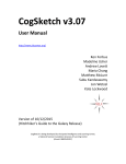
1.7 Dimensions and weight of the terminal
Weight: 3 Kg
The dimensions are given in mm.
Figure 1.1 - Dimensions and weight of table top version
(citi0401.jpg)
1-13
D800
Weight: 4 Kg
The dimensions are given in mm.
Figure 1.2 - Dimensions and weight of rack-mounted version
(citi0402.jpg)
The dimensions are given in mm.
Figure 1.3 - Panel drilling measurements for rack-mounted version
(citi0403.jpg)
1-14
D800
1.8 Obtaining technical assistance
In the event of any operating faults requiring the intervention of
specialised technicians, contact the manufacturer or your nearest
Service Centre. To enable us to deal with your request swiftly, always
quote the serial number of your terminal, which can be found on the seal
label. Also provide information about the system in which the terminal is
installed.
1-15
D800
1.9 Replacement parts list
Replacement parts can ordered directly from the manufacturer or from
your nearest Service Centre.
Code
Description
460727
110/240 Vac power supplier
460740
12-24 Vdc-ac power supplier
169378
Keypad unit for table top version
169393
Keypad unit for rack mounted
version
404021
CPU board
460728
Converter for analogue load cells
403961
Inteface for digital load cellsi
403981
MPP FLASH memory expansion
board
403991
Serial expansion board
404001
Board with 4 inputs / 4 outputs
404061
Board with 4 inputs / 12 outputs
404011
BCD TTL or calculator board
404012
BCD 24V source board
527313
Internal lithium battery
528240
Display
520534
Inverter for display
475052
STB112 standard printer
connection cable
1.10 Warranty
The conditions of warranty are stipulated in the contract of sale.
1-16
D800
2. SAFETY INSTRUCTIONS
2.1 Prohibited uses
The instrument you have purchased is a weighing system and has been
designed and manufactured as such. The instrument is primarily
intended for the weighing of goods.
✔ It is forbidden to use the terminal without taking the necessary
precautions for safe use.
✔ Use of the terminal in places with potentially explosive atmospheres
or in areas where there is a risk of fire is strictly prohibited.
Any other use shall only be permitted if expressly authorised by the
Manufacturer.
2.2 Regulations
The operating conditions for the electronic terminal are subject to the
regulations in force in the country in which the terminal is used. All use
of the terminal in conditions which do not comply with these regulations
is prohibited.
2.3 Prescriptions of use
✔ Strictly comply with the instructions in this manual during use.
✔ In the event of any discrepancy between the information in this
manual and the instrument purchased, contact your Dealer or the
Manufacturer's After-Sales Service for clarification.
✔ Always observe the indications given on the warning and danger
plates on the terminal.
✔ Check that all the safety guards are in place and that the connection
cables are in good condition and connected correctly.
✔ Check that the terminal is connected to an electrical outlet socket
equipped with an effective earth connection. Make sure that the line
complies with the applicable regulations. Check that there is no
difference in potential between the earth and neutral conductors.
✔ If the terminal is to be connected to other devices (e.g. a computer),
these devices must be disconnected from the electrical supply before
connection to the terminal.
1-17
D800
✔ All maintenance and/or repairs must be carried out by authorised
personnel only.
✔ Always disconnect the terminal from the electrical supply and wait a
few minutes before accessing the internal components.
1-18
D800
3. DELIVERY AND INSTALLATION
Key
1. ON/OFF switch
2. Fuses
3. Male 3-pin connector for power supply connection
4. Earth screw
5. Data plate indicating voltage, frequency and fuse types
Figure 3.1 - Rear of terminal (powering part) (citi0404.jpg)
1-19
D800
Key
1. 9-pin female serial port connector (JCOM 3) for connection of
various devices
2. 9-pin female serial port connector (JCOM 1) for printer connection
3. 9-pin female serial port connector (JCOM 2) for connection of
various devices
4. 9-pin male connector (JBIL-B) to connect to optional second
weighing platform (15-pin male connector in the case of digital load
cellsi)
5. 9-pin male connector (JBIL-A) to connect to the first weighing
platform (15-pin male connector in the case of digital cells)
6. Expansion slot 3
7. Expansion slot 2
8. Expansion slot 1
9. Supplementary keypad input
10. Input/Output connection terminals (JI/O)
Figure 3.2 - Rear of terminal (part connecting to scale and auxiliary
outputs) (citi0405.jpg)
1-20
D800
3.1 Connection of the terminal to the electrical supply line
DANGER
Check that:
✔ The voltage and frequency of the electrical supply line
corresponds to the indications on the warning plate on the
rear of the terminal (see point 5 Figure 3.1 on page 1-19);
✔ the mains outlet socket to which the terminal is connected
is equipped with an earth;
✔ the warning and danger signs are present and legible;
✔ failing this, notify your maintenance personnel or contact
our Assistance Service directly;
For the correct connection of the terminal to the electrical supply line,
proceed as follows:
✔ plug the 3-pin connector of the power lead into the connector on the
rear if the terminal;
✔ insert the plug of the power lead into the correct mains outlet socket.
The terminal complies with the European Directive for electromagnetic
compatibility, however it is good practice to provide a separate power
supply line for the terminal.
1-21
D800
WARNING
Do not route the terminal connection cables alongside power
cables as these could cause disturbances that interfere with
the correct operation of the terminal. Only use the connection
cable supplied with the terminal. If the cable supplied is too
short, do not attach an extension lead but contact the
Manufacturer.
3.2 Connection of the terminal to the platform scale
The terminal is normally supplied with a pre-wired cable for connection
to the platform scale. The female connector on this cable should be
plugged into the male 9/15-pin connector (JBIL1 or 2) on the rear of the
terminal (see point 5 Figure 3.2 on page 1-20). The connection method
may vary according to the type of transducer on the platform scale
(analogue or digital). If the scale is the duplex type, scale A should be
connected to connector JBIL1 and scale B to connector.
WARNING
The cable screen should always be connected to the metal
cap of the 9/15-pin connector. Do not route the scale
connection cable alongside power cables.
1-22
D800
3.2.1 Equipotentiality between the terminal and the platform
scale
Check that a condition of equipotentiality exists between the metal parts
of the terminal and the platform scale.
If in doubt, connect the terminal and the scale using a earth wire of at
least 6mm² using the earth screw on the rear of the terminal (see point 4
Figure 3.1 on page 1-19).
The cables required for this connection are to be provided by the
customer.
3.2.2 Connection of analogue load cells
The diagram below shows the pinout for the JBIL connector for
connection to scales with analogue load cells.
Key
NC = Reserved - do not connect
SIG + = Signal +
SIG - = Signal EX + = Excitation +
EX - = Excitation SENSE + = SENSE signal +
SENSE - = SENSE signal -
Figure 3.3 - Pinout for the JBIL connector for connection to scales
with analogue load cells (log0001.gif)
1-23
D800
3.2.3 Connection of digital load cells
Connection to digital load cells is by RS485 serial line using a screened
cable with 6 conductors. The diagram below shows the pinout of the
JBIL connector for connection to platform scales with digital load cells.
Key
EX + = Excitation +
EX - = Excitation DATA +/- = Bidirectional data
transmission line
NC = Reserved - do not connect
Figure 3.4 - Pinout of JBIL connector for connection to scales with
digital load cells (log0002.gif)
Pins carrying the same signals may be connected in parallel.
1-24
D800
3.3 COM1 serial port connection
The terminal has an RS232 serial port (COM1) with a 9-pin female
connector located on the rear panel (see point 2 Figure 3.2 on page
1-20); the diagram below shows the pin connections for this port.
Key
DCD232 = Data Carrier Detect
DSR232 = Data Set Ready
RX232 = Data reception
RTS232 = Request to send
TX232 = Data transmission
CTS232 = Clear to send
DTR232 = Data terminal Ready
RI232 = Ring Indicator
GND = Signal ground
Figure 3.5 - Standard serial port connector (9-pin female D-type)
(citi0406.gif)
CAUTION
Operating limits stipulated by the standard RS232:
Maximum transmission distance = 15 m
Maximum line voltage = ± 12 Vdc
For connection to external devices, use a screened cable
and connect the screen to the metal cap of the 9-pin
connector.
1-25
D800
3.4 COM2 serial port connection
The terminal has second serial port, which can be configured for RS232,
RS422 or RS485 data transmission standards. The serial port (COM2)
has a 9-pin female connector (see point 3 Figure 3.2 on page 1-20).
3.4.1 Connection of COM2 in RS232 configuration
For the connection of external devices, refer to the pinout diagram in
Figure 3.6 on page 1-26:
Key
NC = Reserved - do not connect
RX232 = Data reception
TX232 = Data transmission
GND = Signal ground
Ri = Termination resistance
inside terminal
NOTE: the free pins are
reserved for RS422 - RS485
connection
Figure 3.6 - COM2 serial port connector (9-pin female D-type)
(log0004.gif)
CAUTION
The RS232 operating limits are indicated in par. 3.3 on page
1-25.
1-26
D800
3.4.2 Connection of COM2 in RS422 configuration
Key
NC = Reserved - do not connect
RX422 +/- = Data reception
TX422 +/- = Data transmission
TERMIN = Termination
resistance to be connected to
pin 6
Ri = Termination resistance
inside terminal
NOTE: the free pins are
reserved for RS232 connection
Figure 3.7 - Example of RS422 serial port connection (log0005.gif)
CAUTION
Operating limits stipulated by the standard RS422:
Maximum transmission distance = 1200 m
Maximum line voltage = +/- 7V
For connection to external devices, use a screened twisted
pair cable and connect the screen to the metal cap of the
9-pin connector.
1-27
D800
3.4.3 Connection of COM2 in RS485 configuration
If the COM2 serial port is configured for RS485 data transmission, you
will need to:
✔ connect together pins 9 and 6 and pins 1 and 7 (Figure 3.8 on page
1-28)
✔ place a jumper across pin 6 and pin 8 to connect the termination
resistance; this operation is to be carried out on the first and last
terminals connected in the line
Key
NC = Reserved - do not connect
DATA +/- = Bidirectional data transmission line
TERMIN = Termination resistance to be connected to pin 6
Ri = Termination resistance inside terminal
NOTE: the free pins are reserved for RS232 connection
Figure 3.8 - Pinout for RS485 serial port connection (log0006.gif)
1-28
D800
CAUTION
Operating limits stipulated by the standard RS485:
Maximum transmission distance = 1200 m
Maximum line voltage = +/- 7V
For connection to external devices, use a screened twisted
pair cable and connect the screen to the metal cap of the
9-pin connector.
Maximum number of terminals that may be connected = 16
3.5 COM3 serial port connection
The terminal is equipped with a third serial output as part of standard
supply (COM3). For connections, refer to par. 3.4 on page 1-26. The pin
numbers are the same.
3.6 External keypad connection
An input for a compatible PC keyboard is available in the KBD connector
at the rear of the terminal (point 9 of Figure 3.2 on page 1-20).
CAUTION
Use of the external keyboard inhibits COM2 operation.
1-29
D800
3.7 Printer connection
Unless different instructions are given, the external printer is connected
to the COM1 serial port of the terminal using the supplied cable.
3.8 Input/Output connection
The terminal board JI/O on the rear of the instrument (point 10 Figure
3.2 on page 1-20) provides input and output contacts; Figure 3.9 on
page 1-30 contains the pinout diagram.
Key
Pi = Part inside terminal
Pe = Part outside terminal
Figure 3.9 - JI/O terminal board for Input/Output connections
(log0008.gif)
1-30
D800
CAUTION
Technical characteristics:
Input:
Maximum input voltage = 24Vdc
Maximum input current = 5mA
The inputs can be controlled by a mechanical contact or by
an NPN-type transistor (negative common)
Output:
mechanical voltage-free contact
Maximum switchable voltage = 110 Vac/dc
Maximum switchable current = 200 mA
I/O refresh time = 0.1s
DANGER
When the weighing system is installed in complex plants that
can represent a danger hazard for operators, enlist the
assistance of specialised personnel to perform several
manoeuvres without load in order to acquire the experience
necessary to work in safety.
1-31
D800
1-32
D800
4. CONTROLS, DISPLAY, SWITCHING THE
TERMINAL ON AND OFF
4.1 Display of weight and additional information
Key
1. Editing keys
2. Operating keys
3. Weighing function keys
4. Graphic display
5. Numeric keyboard
6. Alphabetical keyboard
Figure 4.1 - Front of terminal (citi0407.jpg)
1-33
D800
The LCD (Liquid Crystal Display) (point 4 Figure 4.1 on page 1-33), in
addition to the universally recognised weighing symbols, also displays
information (in extended format) related to the operation of the terminal.
Listed below are the weighing symbols displayed and their meanings:
Weight stable symbol
Indicates that the weight value displayed is stable
and thus may be printed and/or transmitted.
Centre zero symbol
Indicates that the weight on the scale is near to
zero i.e. within -1/4 + 1/4 of a division.
Tare symbol
Indicates the presence in memory of an acquired
tare value.
Preset tare symbol
Indicates that a tare value has been entered from
the keypad.
Gross weight symbol
Gross weight symbol with units of
measurement in lb (as alternative to B)
This symbol only illuminates when the unit of
measurement is "lb" (pounds).
Minimum weight
Net weight symbol
Weighing range indication for multi-extension
(ME) instruments
1-34
D800
4.1.1 Selection display symbols
Weight indication
Below preset lower limit.
Weight indication
Within the preset upper and lower limits.
Weight indication
Above the preset upper limit.
1-35
D800
4.2 Weighing function keys
Refer to points 3 of Figure 4.1 on page 1-33:
Zero-set weight
press this key to reset the weight indication only in
the presence of the following condition:
✔ the weight value must be within the -1% to +3%
range of the weighing capacity for terminals
subject to legal verification or ± 50% for other
terminals;
✔ the weight must be stable;
✔ no tare must have been entered.
Enter/cancel tare
On pressing this key, the weight on the scale is
acquired as the tare value, provided the following
conditions are satisfied:
✔ the weight must be stable;
✔ the weight must have a positive value;
✔ the weight must not exceed the maximum
capacity.
Symbols
and
appear on the display.
On MD terminals, the weight indication will be
displayed using the division of the lower range. On
ME terminals, the net weight will be displayed
using the division of the range in within which it
falls.
On pressing
again, the tare will be cancelled
and the terminal will display the gross weight
again.
1-36
D800
Enter/display tare
Pressing this key allows you to enter a tare value
using the numeric keys on the keypad. To change
a preset tare value see par. 5.4.27 on page 1-73.
On completion of the operation, the display will
show the net weight, tare values and symbols
and
will appear. The entered tare value
will be automatically rounded off to the nearest
scale division. On MD terminals, the net weight
will be displayed using the division of the range
within which the net weight value falls, while on
ME terminals, the net weight division shall be that
of the range within which the gross weight falls.
On MD terminals, the maximum preset tare value
is limited to the maximum capacity of the first
weighing extension (indicated on the metrological
data plate).
Print and/or send
Allows a weighing option to be requested.
Consequently forces a weighing data printout
and/or serial transmission of a string of data via
the configured port.
1-37
D800
4.3 Operating keys
Refer to points 2 of Figure 4.1 on page 1-33:
Customizable keys
The function associated with these keys appears
on the display.
Function keys
These keys access functions that can be called up
from the numeric keyboard.
WARNING
The functions of all the keys may change. These changes
are indicated by messages on the display.
4.4 Editing keys
Refer to points 1 of Figure 4.1 on page 1-33:
Cursor keys
Press these keys to move the cursor around the
display.
1-38
D800
Caps key
Allows capital letters to be entered when used in
combination with the alphabet keys.
Allows special characters and punctuation marks
to be entered when used in combination with the
numeric keys.
Cancel key
Allows the newly entered character to be
cancelled.
Caps Lock
Allows the operator to write in capital letters.
4.5 Numeric keyboard
Refer to point 5 of Figure 4.1 on page 1-33:
Numeric keys (0...9).
Press these keys to enter numeric characters or
symbols.
Comma key
This key is used to enter commas in
alphanumerical descriptions.
It is also used to enter the decimal separator
symbol in numeric values.
In this case, it enters the decimal separation
symbol selected during the configuration phase
(dot or comma).
1-39
D800
4.6 Alphabetical keyboard
Refer to point 6 of Figure 4.1 on page 1-33:
Alphabet keys (A...Z)
These normally enter lower case characters. For
capital ones, press
.
Enter key
Used to send or confirm a data item
Owing to printing requirements, this key will be
indicated in the manual by
Space key
Space key.
Owing to printing requirements, this key will be
indicated in the manual by
4.7 External keyboard (optional)
F1-F2: operate in the same way as the key on the panel
F3-F8: Shortcut keys programmable in setup mode (*)
F9 : key
(point 1 of Fig. 4.2 on page 1-41)
F10: key
(point 2 of Fig. 4.2 on page 1-41)
F11: key
(point 3 of Fig. 4.2 on page 1-41)
F12: key
(point 4 of Fig. 4.2 on page 1-41)
1-40
D800
Print: same as print key
Arrows up, down, right, left (↑ ,↓ ,→,←): operates in the same way as
the key on the panel
Page up, Page down: page change during list display
Home, End: go to beginning/end of the table during list display (*)
Canc: operates in the same way as the key on the panel
Backspace: operates in the same way as canc
Shift, Caps lock, Num lock: operate in the same way as a normal PC
keyboard
Double function alphabetical keys with double functions, punctuation
characters: same operation as a normal PC keyboard with the exclusion
of the characters entered by pressing key Alt Gr or Alt + ASCII code
Tab, Esc, Ins, Scroll lock, Pause/Interr: not used
(*) function not currently available
Key
1, 2, 3, 4. Customizable keys
Figure 4.2 - Customizable keys (citi0412.jpg)
1-41
D800
4.8 Switching the terminal on and off
Key
1. ON/OFF switch
Figure 4.3 - On/Off switch (citi0408.jpg)
DANGER
Before switching on the terminal, check that the safety
guards are in place and in good working order.
If the terminal is wall mounted on an electrical panel, there
must be a main switch that disconnect powers to the entire
panel.
To identify this switch, contact your internal maintenance
manager.
1-42
D800
Press the switch on the rear of the terminal (see point 1 Figure 4.3 on
page 1-42) and move it to position:
I
O
to switch on the terminal;
to switch it off
When powered, the display will show the Manufacturer's logo and the
type of operation for which the terminal is enabled (see par. 5.1.5 on
page 1-47).
Wait for the LOCK indication to appear (terminals subject to metrological
verification only).
If on completion of the operation the display shows a value other than
zero , press
to zero-set the reading.
If the display is not zero-set on pressing the key:
✔ check that the platform scale is in fact unloaded. If not, unload the
scale, switch off the terminal and then switch it on again;
✔ If the problem persists, contact your Service Centre.
1-43
D800
1-44
D800
5. USE OF THE TERMINAL
5.1 General
5.1.1 Using the keys to browse the menus
The operating keys described in par. 4.3 on page 1-38 allow you to
browse through the programming menus.
From the normal display status, you can access the menus by using
keys
(or
)+
(point 2 of Fig. 4.2 on page 1-41) to select
the MENU item. After this, the other keys can be used to select the next
data item. The arrows in the menus ↑ ,↓ allow you to move up and
down, respectively.
Use key
to select the item required or to access a sub-menu.
Keys # and \\ can be used to change the mode in which the menu path
is displayed : # path in full, \\ path expressed in numbers.
Select item ESC to return to the previous menu level. From here on in
this manual, the instructions will only indicate the pathway without
referring to the specific keys to be pressed. For example, the instruction
on how to change the contrast will be given as follows:
...>MENU>Contrast>+ or - >SAVE>ESC
5.1.2 Access to the functions
To access the functions, use:
✔ keys
,
the function;
✔ keys
and
,
,
at the sides of the display that indicate
followed by a number. The number to press
appears on the display after
or
1-45
have been pressed.
D800
5.1.3 Special characters
Prolonged pressure on a key will display the special character
associated with it. A list of the special characters associated with the
alphanumerical keys is given in the table below.
Alphanumeric keys
Characters
Key 0
?¿
Key 1
!¡
Key 2
Pt f
Key 3
£
Key 4
$
Key 5
%
Key 6
&
Key 7
[{<
Key 8
]}>
Key 9
;
Key ,
,@
Key A
âäàåÄŪ
Key C
çÇ
Key E
éêëèÉæÆ
Key I
ïîìí
Key N
ñÑ
Key O
ôöòóÖº
Key S
ß
Key U
üûùúÜ
Key Y
ÿ
1-46
D800
Keep any one of ther alphanumerical keys depressed for one second to
call up one of the alternative special characters. Wait one and a half
seconds to confirm the special character. To scroll through all the
special characters associated with a given alphanumerical key,
repeatedly press the key itself.
5.1.4 Shortcut keys
During installation, User menu functions may be assigned to shortcut
keys. In this way the user can access the required function more rapidly.
For example, to access the Product Code function, there is no need to
press:
...>MENU>Totals Management>Total for Client Code
simply press CLTOT.
The abbreviations that appear on the display may be customised during
installation. For this reason, the abbreviations related to the shortcut
keys that appear in brackets alongside or below the pathways described
in the following paragraphs may have been modified by the installer. Ask
your installer for a list of the abbreviations and their meanings.
5.1.5 Operating modes
The terminal can operate in two different modes which also possess
further variants to adapt to different weighing requirements. The two
main operatings modes are: single weighing (described in chap. 6. on
page 1-81) and double weighing (described in chap. 7. on page 1-85).
The operating mode of the terminal is selected during the installation
phase and appears on the display when the instrument is powered.
1-47
D800
5.2 User menu
To access the user menu, press
MENU.
(or
) immediately followed by
5.2.1 User Menu tree for single weighing mode operation
The user menu tree expanded to the third level is given below. Refer to
the subsequent paragraphs for details about the various functions (from
par. 5.4.6 on page 1-64 to par. 5.4.33 on page 1-79).
Scale selection
A
B
C
A+B
A+C
B+C
A+B+C
Data management
Codes management
Product Code List
Client Code List
Generic Code List
TCA Code List
Range
Range 01
Range 02
Range 11
Range 12
Range 13
Range 14
Range 21
Range 22
Range 23
Range 24
Range 31
Range 32
Range 33
Range 34
Setpoint
Setpoint 01
Setpoint 02
Setpoint 11
Setpoint 12
Setpoint 13
Setpoint 14
Setpoint 21
Setpoint 22
Setpoint 23
Setpoint 24
Setpoint 31
1-48
D800
Setpoint 32
Setpoint 33
Setpoint 34
Range on Display
Display MPP data
Preset tares
Preset Tares List
Preset Tares List 1
Preset Tares List 2
Number of Packs
Progressive N.
Coefficient management
Coefficient
Coefficient value
Max.Coefficient (or Min.Coefficient)
Operation
Result
Modifiable Archives
Totals management
General Total
Partial Total
Product Code Total
Client Code Total
Generic Code Total
TCA Total
Weight sum report
Journal Entry Total
MPP operation
De-activated
With memory
With printer
Display
12 mm digits
Selection
Display tare
Contrast
Lighting
Always
Timed
Memory Status
Reprint
Date Time
Diagnostics A
Diagnostics B
Customizable fields
Field 1
Field 2
Field 3
Field 4
Field 5
Field 6
Field 7
Zero set
Cut printer paper
High resolution
1-49
D800
5.2.2 User Menu Tree for double weighing mode operation
Scale selection
A
B
C
A+B
A+C
B+C
A+B+C
Data Management
Codes management
Product Code List
Client Code List
Plate Codes List
RCD List
RCD Plate List
RPD List
RPD Plate List
Range
Range 01
Range 02
Range 11
Range 12
Range 13
Range 14
Range 21
Range 22
Range 23
Range 24
Range 31
Range 32
Range 33
Range 34
Setpoint
Setpoint 01
Setpoint 02
Setpoint 11
Setpoint 12
Setpoint 13
Setpoint 14
Setpoint 21
Setpoint 22
Setpoint 23
Setpoint 24
Setpoint 31
Setpoint 32
Setpoint 33
Setpoint 34
Display MPP data
Progressive N.
Coefficient management
Coefficient
Coefficient value
Max.Coefficient (or Min.Coefficient)
Operation
Result
1-50
D800
Modifiable Archives
Totals management
General Total
Partial Total
Product Code Total
Client Code Total
Plate Total
RPD Total
Journal Entry Total
MPP operation
De-activated
With memory
With printer
Contrast
Lighting
Always
Timed
Memory status
Reprint
Date Time
Diagnostics A
Diagnostics B
Customizable fields
Field 1
Field 2
Field 3
Field 4
Field 5
Field 6
Field 7
Zero set
Cut printer paper
High resolution
1-51
D800
5.2.3 Complete User Menu Tree
Scale selection
A
B
C
A+B
A+C
B+C
A+B+C
Data management
Codes management
Product Code List
Client Code List
Generic Code List
Plate Code List
TCA Code List
RCD List
RCD Plate List
RPD List
RPD Plate List
Supplier Code List
Consignee Code List
Product Code List
Carrier Code List
Plate Code List
Range
Range 01
Range 02
Range 11
Range 12
Range 13
Range 14
Range 21
Range 22
Range 23
Range 24
Range 31
Range 32
Range 33
Range 34
Setpoint
Setpoint 01
Setpoint 02
Setpoint 11
Setpoint 12
Setpoint 13
Setpoint 14
Setpoint 21
Setpoint 22
Setpoint 23
Setpoint 24
Setpoint 31
Setpoint 32
Setpoint 33
Setpoint 34
1-52
D800
Display Range
Display MPP data
Preset tares
Preset Tares List
Preset Tares List 1
Preset Tares List 2
Number of Packs
Progressive N.
Coefficient management
Coefficient
Coefficient value
Max.Coefficient (or Min.Coefficient)
Operation
Result
Modifiable Archives
Totals management
General Total
Partial Total
Product Code Total
Client Code Total
Generic Code Total
Plate Total
TCA Total
RPD Total
Weight sum report
Journal Entry Total
Supplier Code Total
Consignee Code Total
Product Code Total
Carrier Code Total
Plate Code Total
MPP operation
De-activated
With memory
With printer
Display
12 mm digits
Selection
Display tare
Contrast
Lighting
Always
Timed
Memory status
Reprint
Date Time
Diagnostics A
Diagnostics B
Customizable fields
Field 1
Field 2
Field 3
Field 4
Field 5
Field 6
Field 7
Zero set
1-53
D800
Cut printer paper
High resolution
The user menu contains functions that are not normally associated with
the shortcut keys. They can be associated during the installation phase.
These functions are Display, Diagnostics, Change date and
time and Memory status.
1-54
D800
5.3 List of terminal functions
A list of the functions handled by the terminal along with the keys that
allow them to be activated is given below. The functions have been
divided per operating mode since different operating modes may
correspond to different functions and/or different function activating
procedures. Also remember that not all the functions can be accessed
since their availability may depend on their having been activated when
the terminal was configured.
Key
1, 2, 3, 4. Customizable keys
Figure 5.1 - Customizable keys (citi0412.jpg)
1-55
D800
5.3.1 Single weighing functions: standard
(point 1 of Fig. 5.1 on
page 1-55)
Customizable fields
(point 3 of Fig. 5.1 on
page 1-55)
Date time
(point 2 of Fig. 5.1 on
page 1-55)
Scale selection
(point 4 of Fig. 5.1 on
page 1-55)
Totals
F1+0
F1+1
F1+2
F1+3
F1+4
F1+5
F1+6
F1+7
F1+8
F1+9
General Total
Partial Total
Product Code Total
Client Code Total
Generic Code Total
ACT Total
Cut printer paper
MPP operation
MPP code
Progressive number
F2+0
F2+1
F2+2
F2+3
F2+4
F2+5
F2+6
F2+7
F2+8
F2+9
Reprint
Range
Set Point
Display range
Coefficient
Memory status
Contrast
Display
Field1
Field2
5.3.2 Single weighing functions: weight sum mode
(point 1 of Fig. 5.1 on
page 1-55)
Customizable fields
(point 3 of Fig. 5.1 on
page 1-55)
Weight Report
(point 2 of Fig. 5.1 on
page 1-55)
Scale selection
(point 4 of Fig. 5.1 on
page 1-55)
Totals
F1+0
F1+1
F1+2
F1+3
F1+4
F1+5
F1+6
F1+7
F1+8
F1+9
General Total
Partial Total
Product Code Total
Client Code Total
Generic Code Total
Date Time
Cut printer paper
MPP operation
MPP code
Progressive number
F2+0
F2+1
F2+2
F2+3
F2+4
F2+5
F2+6
F2+7
F2+8
F2+9
1-56
Reprint
Range
Set Point
Display range
Coefficient
Memory status
Contrast
Display
Field1
Field2
D800
5.3.3 Single weighing functions: extraction
(point 1 of Fig. 5.1 on
page 1-55)
Customizable fields
(point 3 of Fig. 5.1 on
page 1-55)
Start/Stop
(point 2 of Fig. 5.1 on
page 1-55)
Scale selection
(point 4 of Fig. 5.1 on
page 1-55)
Totals
F1+0
F1+1
F1+2
F1+3
F1+4
F1+5
F1+6
F1+7
F1+8
F1+9
General Total
Partial Total
Product Code Total
Client Code Total
Generic Code Total
Date Time
Cut printer paper
MPP operation
MPP code
Progressive number
F2+0
F2+1
F2+2
F2+3
F2+4
F2+5
F2+6
F2+7
F2+8
F2+9
Reprint
Range
Set Point
Display range
Coefficient
Memory status
Contrast
Display
Field1
Field2
5.3.4 Double weighing functions: RCD + RPD
(point 1 of Fig. 5.1 on
page 1-55)
RPD
(point 3 of Fig. 5.1 on
page 1-55)
RCD
(point 2 of Fig. 5.1 on
page 1-55)
Scale selection
(point 4 of Fig. 5.1 on
page 1-55)
Totals
F1+0
F1+1
F1+2
F1+3
F1+4
F1+5
F1+6
F1+7
F1+8
F1+9
General Total
Partial Total
Product Code Total
Client Code Total
Plate Code Total
RPD total
Cut printer paper
MPP operation
MPP code
Progressive number
F2+0
F2+1
F2+2
F2+3
F2+4
F2+5
F2+6
F2+7
F2+8
F2+9
1-57
Reprint
Range
Set Point
Display range
Coefficient
Memory status
Contrast
Display
Date Time
Customizable fields
D800
5.3.5 Double weighing functions: RCD Plate + RPD
(point 1 of Fig. 5.1 on
page 1-55)
RPD
(point 3 of Fig. 5.1 on
page 1-55)
RCD Plate
(point 2 of Fig. 5.1 on
page 1-55)
Scale selection
(point 4 of Fig. 5.1 on
page 1-55)
Totals
F1+0
F1+1
F1+2
F1+3
F1+4
F1+5
F1+6
F1+7
F1+8
F1+9
General Total
Partial Total
Product Code Total
Client Code Total
Plate Code Total
RPD total
Cut printer paper
MPP operation
MPP code
Progressive number
F2+0
F2+1
F2+2
F2+3
F2+4
F2+5
F2+6
F2+7
F2+8
F2+9
Reprint
Range
Set Point
Display range
Coefficient
Memory status
Contrast
Display
Date Time
Customizable fields
5.3.6 Double weighing functions: RCD + RPD Plate
(point 1 of Fig. 5.1 on
page 1-55)
RPD Plate
(point 3 of Fig. 5.1 on
page 1-55)
RCD
(point 2 of Fig. 5.1 on
page 1-55)
Scale selection
(point 4 of Fig. 5.1 on
page 1-55)
Totals
F1+0
F1+1
F1+2
F1+3
F1+4
F1+5
F1+6
F1+7
F1+8
F1+9
General Total
Partial Total
Product Code Total
Client Code Total
Plate Code Total
Customizable fields
Cut printer paper
MPP operation
MPP code
Progressive number
F2+0
F2+1
F2+2
F2+3
F2+4
F2+5
F2+6
F2+7
F2+8
F2+9
1-58
Reprint
Range
Set Point
Display range
Coefficient
Memory status
Contrast
Display
Date Time
Field1
D800
5.3.7 Double weighing functions: RCD Plate + RPD Plate
(point 1 of Fig. 5.1 on
page 1-55)
RCD Plate
(point 3 of Fig. 5.1 on
page 1-55)
RPD Plate
(point 2 of Fig. 5.1 on
page 1-55)
Scale selection
(point 4 of Fig. 5.1 on
page 1-55)
Totals
F1+0
F1+1
F1+2
F1+3
F1+4
F1+5
F1+6
F1+7
F1+8
F1+9
General Total
Partial Total
Product Code Total
Client Code Total
Plate Code Total
Customizable fields
Cut printer paper
MPP operation
MPP code
Progressive number
F2+0
F2+1
F2+2
F2+3
F2+4
F2+5
F2+6
F2+7
F2+8
F2+9
Reprint
Range
Set Point
Display range
Coefficient
Memory status
Contrast
Display
Date Time
Field1
5.3.8 Double weighing functions: without RCD or RPD with
manual entry of first weight
(point 1 of Fig. 5.1 on
page 1-55)
Customizable fields
(point 3 of Fig. 5.1 on
page 1-55)
Date Time
(point 2 of Fig. 5.1 on
page 1-55)
Scale selection
(point 4 of Fig. 5.1 on
page 1-55)
Totals
F1+0
F1+1
F1+2
F1+3
F1+4
F1+5
F1+6
F1+7
F1+8
F1+9
General Total
Partial Total
Product Code Total
Client Code Total
Plate Code Total
Contrast
Cut printer paper
MPP operation
MPP code
Progressive number
F2+0
F2+1
F2+2
F2+3
F2+4
F2+5
F2+6
F2+7
F2+8
F2+9
1-59
Reprint
Range
Set Point
Display range
Coefficient
Memory status
Display
Field1
Field2
Field3
D800
5.3.9 Double weighing functions: only RCD or RCD Plate
(point 1 of Fig. 5.1 on
page 1-55)
RCD Plate
(point 3 of Fig. 5.1 on
page 1-55)
RCD
(point 2 of Fig. 5.1 on
page 1-55)
Scale selection
(point 4 of Fig. 5.1 on
page 1-55)
Totals
F1+0
F1+1
F1+2
F1+3
F1+4
F1+5
F1+6
F1+7
F1+8
F1+9
General Total
Partial Total
Product Code Total
Client Code Total
Plate Code Total
Date Time
Cut printer paper
MPP operation
MPP code
Progressive number
F2+0
F2+1
F2+2
F2+3
F2+4
F2+5
F2+6
F2+7
F2+8
F2+9
Reprint
Range
Set Point
Display range
Coefficient
Memory status
Display
Contrast
Customizable fields
Field1
5.3.10 Double weighing functions: RPD or RPD Plate
(point 1 of Fig. 5.1 on
page 1-55)
RPD Plate
(point 3 of Fig. 5.1 on
page 1-55)
RPD
(point 2 of Fig. 5.1 on
page 1-55)
Scale selection
(point 4 of Fig. 5.1 on
page 1-55)
Totals
F1+0
F1+1
F1+2
F1+3
F1+4
F1+5
F1+6
F1+7
F1+8
F1+9
General Total
Partial Total
Product Code Total
Client Code Total
Plate Code Total
RPD Total
Cut printer paper
MPP operation
MPP code
Progressive number
F2+0
F2+1
F2+2
F2+3
F2+4
F2+5
F2+6
F2+7
F2+8
F2+9
1-60
Reprint
Range
Set Point
Display range
Coefficient
Memory status
Display
Contrast
Date Time
Customizable fields
D800
5.4 Description of the functions
5.4.1 Lists: use
WARNING
Paragraphs 5.4.1 on page 1-61 ... 5.4.5 on page 1-63 display
the "browsing" modes and how to edit the lists or tables in
the terminal.
The arrow keys
through the tables.
,
,
,
allow the operator to "browse"
Prolonged pressure on keys
allows you to quickly move
amongst the various columns of a record while prolonged pressure on
keys
accesses the "PAGE UP" and "PAGE DOWN"
functions.
When a "cell" in the table is highlighted, the name of the highlighted
column is moved to a line at the bottom of the display along with the
value in the cell.
5.4.2 Lists: code recall
The required list can be accessed by scrolling the menu, from the work
page (if the list required is in the work page) or by pressing the
corresponding shortcut key (if available).
Digitize the code; during the setting phase, the cursor will move to the
code nearest to the one being selected.
Once the setting phase has terminated, you must press the
again to process the entered code, otherwise you can quit the list
without processing the digitized code by pressing ESC.
1-61
key
D800
5.4.3 Lists: item insertion
The required list can be accessed by scrolling through the menu, from
the work page (if the required list is in the work page) or by pressing the
corresponding shortcut key (if available).
Press key
.
The name of the highlighted column, a symbol → (attesting to the
insertion operation) and the characters being digitized, will appear in the
bottom line.
Press key
again to return to the list scrolling mode.
Enter the code and press
(this will become the "code" that
allows you to univocally identify the list record).
If necessary, you can also load the associated fields by moving to the
required column with the arrows, digitizing the required values and
pressing
.
Once the parameter setting phase has terminated, press
again
to process the newly entered code. You can also enter a new record by
moving to the first column or quit the list without processing the digitized
code by pressing ESC.
1-62
D800
5.4.4 Lists: print-out
The required list can be accessed by scrolling through the menu, from
the work page (if the required list is in the work page) or by pressing the
corresponding shortcut key (if available).
Press the print key
Press key:
.
✔ SELECT key to print out the selected code
✔ ALL to print out the entire table
✔ INTERV to print out a section of the table. In this case, enter the first
and last code that define the section after having pressed the key.
5.4.5 Lists: code deletion
The required list can be accessed by scrolling through the menu, from
the work page (if the required list is in the work page) or by pressing the
corresponding shortcut key (if available).
Press key
Press key:
.
✔ SELECT to delete the selected code
✔ ALL to cancel the entire table
✔ INTERV to cancel a section of the table. In this case, enter the first
and last code that define the section after having pressed the key.
1-63
D800
5.4.6 Scale selection (available in terminals with more than
one scale)
Allows the operator to select the scale to use for the weighing operations
from amongst those connected to the terminal. Once selected, the zero
setting, tare entry, tare acquisition, print-out, I/O management and
transmission functions will refer to the scale in question.
In terminals enabled to operate with several "combined" scales, scale
selection also allows the operator to obtain the sum of the weights from
more than one weighing platform.
To change the scale selected, press SELSCL or follow pathway
...>MENU>Scale selected and move to the required scale.
5.4.7 Adjusting the contrast
To adjust the contrast of the display, follow the pathway:
...>MENU>Contrast
(Shortcut key CONTR)
Press + or - to adjust the contrast. Press key INVER to change the
background colour. To save the new setting in the memory press SAVE.
5.4.8 Lighting
Select Always for permanently enabled backlighting, otherwise select
timed and the backlighting will switch off automatically 10 minutes after
the terminal has failed to detect weight variations or keys pressed. Just
press any key or make a weight variation to turn on the backlighting
again.
1-64
D800
5.4.9 Changing the date and time
Follow the pathway:
...>MENU>Date Time
(Shortcut key DATIME)
To change quickly from summer to winter time, press + or - 1 hour,
alternatively use the option CHANGE.
5.4.10 Weight display (only available in single weighing mode)
You can change the way the weight value is displayed on the terminal.
The current weight display mode will depend on the type of operating
mode set during installation.
To select the display mode follow the pathway:
...>MENU>Display
(Shortcut key VISUAL)
The available display modes are:
✔ 12 mm digits
The display shows the gross weight (or net), the weighing symbols
and any possible accessory data (codes, etc.).
✔ Selection
In addition to the weight and the usual weighing symbols, the display
shows one of the following symbols
.
To select the range, press DRANGE.
The displayed range described here is independent from the range
associated with the outputs.
1-65
D800
✔ Display tare
In addition to the usual weighing symbols, the terminal can also
simultaneously display the net weight and the tare (if entered).
The following indications are displayed:
✔ If the tare has been entered by pressing
were not set during installation:
and multiple tares
Tare: tare value + unit of measurement
Indications
and
will also be illuminated.
✔ If the tare was acquired by pressing
not been set:
and multiple tares have
Tare: tare value + unit of measurement
Indications
and T will be illuminated.
✔ If the rate is preset (par. 5.4.27 on page 1-73 and multiple tares
have not been set:
Tare C: preset tare value + unit of measurement
Indications
and PT will be illuminated.
NOTE: the indication Tare C means that the tare displayed is a
"coded" tare to which a numeric code has been assigned (par.
5.4.27 on page 1-73).
1-66
D800
✔ If multiple rates were set during installation:
Tare T: acquired tare value + unit of measurement
Tare 1 PT: preset tare 1 value + unit of
measurement
Tare 2 PT: preset tare 2 value + unit of
measurement
Or
Tare C PT: preset tare value + unit of
measurement
Tare 1 PT: preset tare 1 value + unit of
measurement
Tare 2 PT: preset tare 2 value + unit of
measurement
Or
Tare PT: "non coded" tare value + unit of
measurement
Tare 1 PT: preset tare 1 value + unit of
measurement
Tare 2 PT: preset tare 2 value + unit of
measurement
Indications
and PT will be illuminated.
NOTE: Tare 1 and Tare 2 may also be recalled via numeric
code (par. 5.4.27 on page 1-73).
1-67
D800
5.4.11 Memory status
If there is insufficient vacant memory, memory can be recovered by
following the pathway:
...>MENU>Memory status
CAUTION
The memory recovery operation may require a few minutes
during which time the terminal cannot be used. Do not switch
off the terminal during this operation as this could result in
loss of the data in the memory.
5.4.12 Reprint
See par. 5.5.1 on page 1-80.
5.4.13 Diagnostics A - Diagnostics B (only for terminals
connected to digital load cells)
Diagnostics A refers to scale A.
Diagnostics B refers to scale B (if installed).
This user menu item is only available when there are digital cell errors
(par. 10.2 on page 1-124). It allows you to identify what caused the error.
Follow this path:
...>MENU>Diagnostics
If the instrument is not subject to calibration checks, CONT can be
pressed to display the measured weight despite the error.
Remember that this can only be done in the case of serial number errors
or ones due to non-configured digital cells.
The error message will reappear when the terminal is powered again
unless the cause of error is eliminated.
1-68
D800
5.4.14 Setting the outputs as Set-points (if enabled)
The two available outputs may be used in setpoint mode. In this way, the
output is activated when the weight reaches the set value.
...>MENU>Data management>Set Point
(Shortcut key SETPNT)
5.4.15 Setting the outputs as Ranges (if enabled)
The two available outputs may be used in Range mode. The output is
activated when the weight is within the set range. To set the range,
follow pathway:
...>MENU>Data management>Range
(Shortcut key RANGE)
5.4.16 Product code
Allows the product codes table to be accessed for entries or recalls. The
product code is a numeric code with a maximum 4 digits or an
alphanumerical code of 10 characters, while the alphanumerical
description that can be associated with the code may be up to 20
characters long. To enter a product code, follow the pathway:
...>MENU>Data management>Code management>Product code
list
(Shortcut key PROCOD)
1-69
D800
5.4.17 Client code
Allows the client codes tables to be accessed for entries or recalls. The
client code is a numeric code with 4 digits or an alphanumerical code
with 10 characters, while the alphanumeric description that can be
associated with the code may be up to 20 characters long. To enter a
client code, follow the pathway:
...>MENU>Data management>Code management>Client code
list
(Shortcut key CLIENT)
5.4.18 Generic code (only available in single weighing mode)
Allows the generic codes tables to be accessed for entries or recalls.
The generic code is a numeric code with 4 digits or an alphanumerical
code of 10 characters, while the alphanumerical description that can be
associated with the code may be up to 20 characters long. To enter a
generic code, follow the pathway:
...>MENU>Data management>Code management>Generic code
list
(Shortcut key GCCOD)
5.4.19 Plate (only available in double weighing mode)
Allows access to the plate codes tables for entries or recalls. The plate
code is an alphanumerical code of 10 characters, while the
alphanumerical description that can be associated with the code may be
up to 20 characters long. To enter a plate code, follow the pathway:
...>MENU>Data management>Code management>Plate code
list
(Shortcut key PLATE)
1-70
D800
5.4.20 Coefficient code
Allows you to enter a number that will be multiplied (or divided) by the
weight value. This function can be of use when the unit of measurement
needs to be converted. For example, you can calculate the number of
litres if the specific weight and overall weight of a liquid are known.
Follow this path to handle the coefficient:
...>MENU>Data management>Coefficient management
(Shortcut key COEF)
On accessing the page, proceed by pressing
to access the
coefficients table where the value of the required coefficient can be
entered. After this, select the required type of operation (multiplication
or division) and therounding value for the result. This latter is just a
numeric value without unit of measurement.
Each group of data can be recalled by means of a numeric code with 4
digits or an alphanumerical code with 10 characters.
5.4.21 Data recall (only available in double weighing mode)
See par. 7.1.1 on page 1-86.
5.4.22 Plate recall (only available in double weighing mode)
See par. 7.1.4 on page 1-91.
1-71
D800
5.4.23 Preset plate recall (only available in double weighing
mode)
See par. 7.2.2 on page 1-94.
5.4.24 Preset weight recall (only available in double weighing
mode)
See par. 7.2.2 on page 1-94.
5.4.25 TCA codes (only available in single weighing mode)
An archive called TCA can be formed in order to load various data items
into the terminal memory at the same time, but in a single setting.
The codes of the Product, Client, Generic and Coefficient archives can
be recalled and activated (if used) and the tare value can also be loaded
(or tares, in the case of multiple tares). The code used to save/recall this
archive can either be a numeric one with 4 digits or an alphanumerical
one with 10 characters. An alphanumerical description with up to 20
characters can also be associated with the record of the TCA archive.
Follow this path to access the TCA menu:
...>MENU>Data management>Tca code list
(Shortcut key TCA)
1-72
D800
5.4.26 Display range (only available in single weighing mode)
Allows the operator to set the range values which, once reached,
change the status of the indications on the display.
These values are independent from the ones set the the outputs (if any)
and do not activate these latter.
These values can only be set if the Seletion display mode is selected.
Follow the pathway:
...>MENU>Data management>Display range
(Shoftcut key DRANGE)
5.4.27 Preset tares (only available in the single weighing
mode)
In the addition to management of tares acquired from the weight on the
scale and tares entered via the keypad, the terminal also manages an
archive of preset tares containing a number of values defined during the
installation phase. Each value can be recalled by way of a numeric code
of 4 digits. Once they have been recalled by entering the relative code,
preset tares are automatically subtracted from the weight on the scale.
Preset tare codes may be entered by following the pathway:
...>MENU>Data management>Preset tare
(Shortcut keys TAREC1 to recall the Preset tare 1 list and
TAREC2 to recall the Preset tare 2 list).
1-73
D800
Functions Preset tare 1 list and Preset tare 2 list allow
you to recall a tare memorized in the multiple tare register by digitizing
the relative code. These functions are only available if the terminal has
been enabled to operate with multiple tares during the installation phase.
The tare 2 value can be multipled by a number, designated Packs
number, which may be entered via the keypad to obtain a tare sum
value (e.g. the sum of the tares of n containers of the same weight). The
result is subtracted from the gross weight. Press shortcut key PACKSN to
enter the number of packs. Functions Preset tare 1 list and
Preset tare 2 list, together with the Packs Number, allow
products with both primary (e.g. pallets) and secondary (e.g. boxes)
packaging to be weighed.
5.4.28 Progressive number
The terminal handles a 6-digit progressive number used to count the
number of weighing operations performed: this value starts from 1 and is
automatically increased by one unit after each print and/or weighing
operation (it therefore indicates the value of the next print or weighing
operation).
To change the progressive number, follow the pathway:
...>MENU>Data management>Progressive
(Shortcut key PROG.N)
If the progressive number = 0 (zero), it will neither be increased nor
printed.
1-74
D800
5.4.29 Modifiable archives
The terminal can inhibit accidental modification or deletion of archive
records by setting to NO.
If NO is to be switched to YES, a numeric password must be entered in
the Setup phase.
5.4.30 Totals management
The terminal provides functions for totalizing the weighing data
associated with the various codes. The totalizing operation involves
adding the current weight value to the sum of the previous weights and
increasing the number of weighing operations by one. To access the list
of available Totals, follow the pathway:
...>MENU>Totals management
(Shortcut key TOTALS)
✔ General totals
These totalizing functions provide general totals for the gross weight
(in single weighing mode), net weight, tare (in single weighing mode)
and the number of weighing operations regardless of any codes
associated. The data can be obtained using the following functions:
...>MENU>Totals management>General total
(Shortcut key GENTOT)
...>MENU>Totals management>Partial total
(Shortcut key PARTOT)
A print can be obtained for each total by pressing the
zero setting with RESET.
1-75
key or by
D800
✔ Totals by code
Saves the gross weight, tare, net weight, the result and number of
weighing operations associated with: product code, generic code
(single weighing mode only), client code, TCA code (single weighing
mode only), plate code (double weighing mode only) and RPD code
(double weighing mode only). The data can be accessed through the
following functions:
...>MENU>Totals management>Product code total
(Shortcut key PROTOT)
...>MENU>Totals management>Generic code total
(Shortcut key GCTOT)
...>MENU>Totals management>Client code total
(Shortcut key CLTOT)
...>MENU>Totals management>TCA code total
(Shortcut key ACTTOT)
...>MENU>Totals management>Plate total
(Shortcut key PLATET)
...>MENU>Totals management>RPD total
(Shortcut key RPD.T)
1-76
D800
Once the totals menu has been selected, you can:
✔ print out the total of a single code by pressing
followed by
SELECT. At the end of the printing phase, the printed totals can be
reset by responding YES to the query;
✔ print out the entire totals table for that type of code by pressing
followed by ALL. At the end of the printing phase, the printed
totals can be reset by responding YES to the query;
✔ print out the totals of a given range of codes by pressing
followed by INTERV.
✔ Reset the totals by pressing
Press key:
.
✔ SELECT to delete the selected code
✔ ALL to delete the entire table
✔ INTERV to delete a section of a table. In this case, enter the
first and last code that define the section in question.
✔ Journal entry total
In this version, the codes entered and the net (net weight), gross,
tare, number of weighing operations, date (day and month) and time
(hours and minutes) are saved for each weighing operation (second
weight in the case of double weighing mode).
This saves the "history" of the weighing operations after which the
totals can be extracted in advanced search mode (e.g. the net weight
transported by carrier X to consignee Y provided by supplier Z can be
found).
The decision to totalize in this type of mode limits the overall
capacitity of codes that can be memorized owing to the larger amount
of memory that this operation requires, using 30 generic codes, 30
product codes and 30 carrier codes. About 3000 weighing operations
(sufficient to cover 300 weighing operations per day for 10 days) can
be saved with the standard memory. The conventional totals, i.e.
partial, general and per single code, are obviously still available.
1-77
D800
To access the totals in journal entry mode, the search rules must be
created in order to define how the data are to be summed.
The procedure is as follows:
✔ access ...>MENU>Totals management or press the shortcut
key TOTALS;
✔ press DBASE;
✔ use the arrows to select the items corresponding to the required
codes;
✔ enter the code number and confirm with
✔ press ESC;
✔ the data will appear on the display. Press
print-out.
An example of a configuration page is given below.
;
if you need a
Configure a search for:
→ Client code: 10
Product code:
Carrier code:
The totals mask per client code in the journal entry format will be:
Client
C.
Product Generic
C.
C.
Gross
Tare
Net
Weighing
N.
10
1
100230
540
25
515
1
10
1
2548
620
25
595
1
10
3
3684
580
20
560
1
10
4
565464
470
15
455
1
✔ Weight sum report (only available in the weight sum function of
the single weighing mode)
See par. 6.2 on page 1-82.
1-78
D800
5.4.31 Display MPP data item
See par. 8.7 on page 1-114.
5.4.32 MPP operation
See par. 8.7 on page 1-114.
5.4.33 Customizable fields
Allows access to 7 fields that can be customized by the user and within
which texts can be entered. They can also be printed. The description of
the functions occurs during the installation phase of the terminal when
the operator can enter associated numerical texts 22 characters in
length.
The functions are accessed by following the pathway:
...>MENU>Fields
(Shortcut key FIELDS)
5.4.34 Cut paper function
This allows the cutter on the printer to be managed if a printer of the
STB112 type is used with "NO" paper cutting mode.
...>MENU>Cut printer paper
(Shortcut key CUT)
5.4.35 Timed high resolution mode
Allows the weights of the scales to be displayed for 4 seconds in high
resolution mode, i.e. in tenths of a division.
...>MENU>High resolution
(Shortcut key HIRES)
1-79
D800
5.5 Printing weighing data
The printer is normally connected to the terminal by way of the COM1
serial port (par. 8.9 on page 1-119).
Print-outs are obtained by pressing
. Printing is performed if:
✔ the weight is valid, i.e. not less than zero and not more than the
maximum scale capacity;
✔ the weight is stable;
✔ the printer is connected, powered, there are no other print jobs
currently in progress and there is paper in the printer.
The data printed are specified each time in the manual. If the relative
function is enabled, the product code and net weight may be printed in
the form of a bar code.
The print-out can be customized using a PC and a specific program:
contact your dealer for further information.
Consult the instruction manual of your printer for details regarding
printing characteristics, paper format, printer maintenance, etc.
5.5.1 Weighing data reprint
Allows the last weighing operation carried out to be reprinted without
changing the progressive number or any totals that may have been
calculated.
The original print can only be distinguished from the reprint if the
terminal is operating in calibrated mode. In this case, the word Reprint
will appear on the latter version.
To obtain a reprint, follow the pathway:
...>MENU>Reprint
(Shortcut key REPRIN)
1-80
D800
6. SINGLE WEIGHING MODE
The terminal operates in "single weighing" mode when all the weight
data (gross, net and tare) appear on a single print. Single weighing
mode can be characterized by the following operating modes: Standard,
sum weighing, loading and unloading extraction.
6.1 Standard operation
In standard operating mode, the terminal can acquire the gross (or net)
weight on the scale and display it along with the weighing symbols. It
can also print the value if the printer is installed.
In this case, the available display formats are Standard and
Selection (see par. 5.4.10 on page 1-65).
The printed data are:
✔
✔
✔
✔
✔
✔
✔
✔
date and time
progressive number
product code (if entered)
client code (if entered)
generic code (if entered)
Gross (if required)
Tare (if entered)
Net
To print, press
, and make sure that:
✔ the weight is stable;
✔ the weight value is not negative or overloaded.
1-81
D800
6.2 Sum weighing operation
The sum weighing operating mode allows you to perform several
weighing operations in sequence without unloading the scale, zero
setting the net weight after each operation. To move from one weighing
operation to the next, press
when the weight is stable.
On completion of this operation:
✔ the net weight is zero-set and the weight currently on the scale is
taken as the tare;
✔ a string is sent to the serial port or the data are printed (if a printer is
connected).
On termination of the weighing operations, obtain the total weight and
return to the gross weight by pressing REPORT.
The display formats available in this operating mode are Standard and
Selection (see par. 5.4.10 on page 1-65).
6.3 Loading extraction operation
When selected and associated with the I/O devices, this operating mode
allows you to perform simple dosing operations with a number of
different components.
The I/O are selected during the installation phase.
Comply with the instructions in par. 5.4.14 on page 1-69 and enter the
Set Point 01 and Set Point 02 values. Set Point 01 defines the final
weight value to extract, Set Point 02 gives the weight value that,
subtracted from the Set Point 01 value, marks the change from fast
extraction mode to slow extraction mode.
Press the key corresponding to the START indication to zero-set the
extracted weight and enable scale loading. The display shows the gross
weight (the weight on the scale) and the extracted weight (the weight
gradually loaded on to the scale). The extraction operation can be
concluded by pressing STOP.
The display format used is the Extraction type (see par. 5.4.10 on
page 1-65).
1-82
D800
Press button
✔
✔
✔
✔
✔
✔
✔
to print-out the following weighing data:
date and time
progressive number
product code (if entered)
client code (if entered)
generic code (if entered)
Gross
Extracted
6.4 Unloading extraction operation
This operating mode is identical to the previous mode expect that in this
case, you start with a loaded scale and gradually remove material.
Enter the Set Point 01 and Set Point 02 values (par. 5.4.14 on page
1-69).
Press the key corresponding to the START indication to zero-set the
extracted weight and enable scale unloading. The display will show the
gross weight (the weight on the scale) and the extracted weight (the
weight unloaded from the scale). The extraction operation can be
concluded by pressing STOP.
Press key
✔
✔
✔
✔
✔
✔
✔
to print out the following weighing data:
date and time
progressive number
product code (if entered)
client code (if entered)
generic code (if entered)
Gross
Extracted
1-83
D800
1-84
D800
7. DOUBLE WEIGHING MODE
DOUBLE WEIGHING options are most commonly used for weighing
means of transport, which are weighed prior to loading and then again
after loading, to determine the quantity of goods that are being
transported.
Double weighing options can be carried out with:
✔ entry-exit operations;
✔ preset weight operations.
Entry-exit operations can be carried out with:
✔ data recall (4 numbers) which are automatically assigned for
entry-exit operations (abbreviated with RCD in this text);
✔ data recall with a vehicle licence plate (10 characters) for entry-exit
operations where the licence plate is entered before each weighing
operation (RCD Plate);
✔ without data recall codes for entry-exit operations, where the entry
weight is entered before each exit weighing operation.
Preset weight operations can be carried out with:
✔ data recall (4 numbers) for preset weight operations (RPD);
✔ data recall with a vehicle licence plate (10 characters) for preset
weight operations (RPD Plate).
1-85
D800
7.1 Entry-Exit functions
Entry-Exit functions require two weighing operations:
✔ an entry weighing operation when the weight of the means of
transport is taken as first weight and, together with auxiliary data
(product code, client code, vehicle licence plate and coefficient), is
given a recognition code;
✔ an exit weighing operation when, having retrieved the first weight and
any auxiliary data using the recognition code, the weight of the
vehicle is recorded as the second weight and then the difference
between the two is calculated (to give the net weight).
The recognition code used during these procedures can be a data recall
code (RCD with 4 figures) or a vehicle licence plate code (RCD Plate
with 10 characters).
The two types of code are for two different methods of carrying out entry
weighing.
7.1.1 Entry operations in Entry/exit mode with Data recall
This type of procedure is enabled during the installation phase.
The entry and exit operating phases do not necessarily have to be
progressive. The difference between the entry and exit weights can be
calculated at the time of the second weighing.
For each entry print-out, the terminal allocates and prints out a code (the
RCD code). If this is entered before the second weighing, the data from
the first weighing (weight, product code, client code, vehicle licence
plate, coefficient, date, time and progressive number) are recalled.
1-86
D800
To obtain a print-out of the entry weight, or first weight:
✔ enter the required auxiliary data: product code, client code, licence
plate of the vehicle and coefficient (if such data need to be recorded);
✔ make sure that the printer is connected, powered and that it contains
paper;
✔ press key
to print out the first weight.
Printing will only take place if:
✔ the weight stabilizes within 10 seconds;
✔ the weight is not negative or over the maximum weight capacity.
The data printed out are:
✔
✔
✔
✔
✔
✔
✔
✔
✔
date
time
a progressive number
product code with details (if entered)
client code with details (if entered)
licence plate with details (if entered)
RCD code
first weight
any texts that may have been entered (see par. 5.4.33 on page 1-79)
The data relating to the first weighing operation are retained in the
memory until the second weight is printed out. After this, the data are
cancelled together with the data recall code.
The RCD archive can hold up to 300 elements (the number of elements
can be modified during the installation phase).
If the terminal has memorised almost the maximum number of RCD
codes, a message will appear asking for the archive to be resized.
1-87
D800
7.1.2 Exit operations in entry/exit mode with Data Recall
The terminal is only able to print out the second weight after the operator
has recalled the RCD code of the first weight. Proceed in the following
way:
✔ Press RCD.
✔ Enter the RCD code after having read it on the print-out of the entry
weighing operation.
If the code shown is the one required, merely confirm it by pressing
.
The product code, client code and vehicle licence plate will be displayed
along with their relative details registered during the entry operation. The
operator can modify these by entering the desired information or by
accessing the relative list. Each setting must be confirmed by pressing
.
Press key
to start the exit operation.
To cancel the operation, press
in the work window.
Remember that once the RCD code has been recalled, you can also
modify the product code, the client code and the licence plate by using
the PROCOD, CLIENT and PLATE keys. These changes will only appear
on the print-out of the second weight and do not change the data
associated with the first weight.
1-88
D800
Printing will only take place if:
✔ the weight stabilizes within 10 seconds;
✔ the weight is not negative or over the maximum weight capacity.
The data printed depend on the printer connected or the configuration
chosen for the first weighing.
✔ If you print on a multicopy card printer, the printed data will be: date,
time, progressive number, product code with relative details, client
code with relative details, licence plate with relative details, RCD
code, first weight, second weight, net weight, coefficient and result (if
enabled).
✔ If you print on a continuous sheet printer, the printed data will contain
all the information given for first weighing plus: date, time, progressive
number, product code with relative details, client code with relative
details, licence plate with relative details, RCD code, first weight,
second weight, net weight, coefficient and result (if enabled).
If the weighing operation terminates correctly, the requested totals are
added up, the next progressive number is used and the RCD code and
its relative data are cancelled.
1-89
D800
7.1.3 Unused RCD code recovery
The following procedure enables the entry operations again when
second weighing procedures cannot be accomplished:
✔ access the list of RCD codes using the path below
...>MENU>Data management>Code management>RCD list
(Shortcut key RCD)
✔ check how many RCD codes the archive contains. Remember that
the archive contains RCD codes for which only the entry weighing
procedure has been carried out.
✔ to print out the list of RCD codes and their relative details, press
followed by ALL to print out the entire list, SELECT to print out a
single code, INTERV to print out a section of the list. In this last case,
you must enter the beginning and end of the section required.
✔ To cancel or zero any unused RCD codes when it will be impossible
to take any future readings, press
followed by ALL to zero the
entire list, SELECT to cancel a single code, INTERV to cancel a a
section of the list. In this last case, you will also need to enter the
beginning and end of the section.
1-90
D800
7.1.4 Entry/Exit operations with Licence Plate Data Recall
The RCD Plate code consists of a maximum of 10 alphanumerical
characters which the operator enters manually and which must be set
before each entry weighing operation. A description 20 characters long
can be associated with the Plate code.
Proceed in the following way:
✔ Access the list of RCD Plate codes following the pathway
...>MENU>Data management>Code management>RCD Plate
list
(Shortcut key RCDPLT)
✔ Press key
to enable entries in the list (see par. 5.4.1 on page
1-61).
✔ Enter the licence plate (max. 10 characters) and confirm it with
. If the licence plate list already contains the entered licence
plate (pathway ...>MENU>Data management>Code
management>Plate code list or shoftcut key PLATE), the
associated description will be automatically displayed.
✔ Move to the description field with the
key. If the description
already exists, it can be modified without altering the one already
memorized with the same licence plate number in the Plate Code
List. If there is no such description, a new description value can be
entered without leading to a setting in the Plate Code List.
✔ If a description value is entered, confirm it by pressing
.
✔ Press
to quit the RCD Plate List and confirm use of the
licence plate for the weighing operation.
Refer to par. 7.1 on page 1-86 for the extry/exit procedure. In this case,
the reference key is not RCD but RCDPLT.
1-91
D800
Unlike RCD mode, the printed data are:
✔ date
✔ time
✔ progressive number
✔ product code with relative details (if entered)
✔ client code with relative details (if entered)
✔ RCD Plate with relative details
✔ the weight data of the weighing operation in progress
✔ any texts that may have been entered (see par. 5.4.33 on page 1-79)
Remember that in the case of RCD Plate, information about the first
weighing is associated with the licence plate of the vehicle on entry.
The card need not be printed in this case, since the first weighing data
can be recalled by setting the vehicle licence plate again when the
vehicle reaches the exit.
The procedure can be configured in both modes during the installation
phase:
✔ with data print-out;
✔ with data memorizing.
The selected mode will appear on the display when the machine is
powered.
WARNING
The explanations given in par. 7.1 on page 1-86 about
printing, the size of the archive, unused weight recovery and
so forth, are also valid for RCD Plate mode. In this case
however, the relevant key is RCDPLT and not RCD.
1-92
D800
7.2 Preset weight options
The preset weight options are used when the first weight (or tare) of a
vehicle is known and therefore do not need to be weighed.
The preset weights are associated with a code that can be used to recall
them.
Besides the preset weight, each code can also store auxiliary
information such as the product code, client code, licence plate and
coefficient.
Remember that such data can also be entered afterwards on the
print-out by using the PROCOD, CLIENT, PLATE and COEF keys. In this
case however, the information is not memorized together with the code
and is valid only for the operation in progress.
The recognition code used during these procedures can be the data
recall type with preset weights (RPD with 4 figures or 10 alphanumerical
characters) or the plate type (RPD Plate with 10 alphanumerical
characters) decided during the installation phase.
7.2.1 How to make the list of preset weights
As indicated previously, the preset weights can be associated with an
RPD or RPD Plate code.
The list of preset weights is made in the following way.
Carry out the following operations (see par. 5.4.1 on page 1-61):
✔
✔
✔
✔
✔
✔
✔
✔
press RPD (or PPLATE);
enter the desired code;
enter the weight to be memorized;
enter the product code;
enter the client code;
enter the plate (if it is not RPD Plate);
enter the coefficient;
repeat the procedure to enter a new code.
1-93
D800
7.2.2 Weighing procedures with preset weights
Once the vehicle is on the weighing scales, press RPD (or PPLATE) and
enter the desired code to recall the first weight preset by the list, the
associated data and then confirm with
.
The weight on the scales, the preset weight code and the preset weight
will appear on the display.
Press
for a print-out of the weight. The following data will be
printed on the print sheet:
✔
✔
✔
✔
✔
✔
✔
✔
✔
✔
date and time
progressive number
product code and details (if entered)
client code and details (if entered)
licence plate and details (if not RPD Plate)
RPD code (or RPD Plate) and relative 1st associated weight
2nd weight
net weight
coefficient and result (if enabled)
any texts that may have been entered (see par. 5.4.33 on page 1-79)
1-94
D800
7.3 Options for entering the first weight manually
In the installation phase, you can choose the option that allows the first
weight to be entered manually.
This operating mode can be enabled individually. However, it is always
enabled with the self-assigned data recall or with the data recall from
Plate operating modes.
If enabled singly, the entry operation can also be accomplished
otherwise only the exit operation can be carried out.
The entry operation is only printed and the relative data, including the
first weight, have to be re-entered manually when the second weighing
operation is carried out.
The first weight is entered by moving to the "WEIGHT 1 R." window and
digitizing the weight.
Confirm with
.
The value of the entered weight must be between 0 and the maximum
capacity.
Press
to obtain a print-out of the weight.
1-95
D800
1-96
D800
8. OPTIONS
Optional expansion boards (with the exception of the MPP memory
expansion board) are installed in the slots provided on the rear of the
terminal (see points 6, 7 and 8 Figure 3.2 on page 1-20).
For the positions and numbering of the outputs (I/O, COM, BCD), refer
to the label on the bottom of the terminal.
Figure 8.1 - Outputs identification label on base of terminal
(citi0410.jpg)
The numbering of the I/O points, the serial ports and the BCD ports is to
be considered along with the position of the boards in the slots (see
Figure 3.2 on page 1-20).
1-97
D800
Inputs
N°input
Slot
CPU board (slot0)
Slot1
Slot2
Slot3
designation
IN 1
INPUT 01
IN 2
INPUT 02
IN 1
INPUT 11
IN 2
INPUT 12
IN 3
INPUT 13
IN 4
INPUT 14
IN 1
INPUT 21
IN 2
INPUT 22
IN 3
INPUT 23
IN 4
INPUT 24
IN 1
INPUT 31
IN 2
INPUT 32
IN 3
INPUT 33
IN 4
INPUT 34
1-98
D800
Outputs
Slot
CPU board (slot0)
Slot1
Slot2
Slot3
N°output
designation
OUT 1
OUTPUT 01
OUT 2
OUTPUT 02
OUT 1
OUTPUT 11
OUT 2
OUTPUT 12
OUT 3
OUTPUT 13
OUT 4
OUTPUT 14
OUT 1
OUTPUT 21
OUT 2
OUTPUT 22
OUT 3
OUTPUT 23
OUT 4
OUTPUT 24
OUT 1
OUTPUT 31
OUT 2
OUTPUT 32
OUT 3
OUTPUT 33
OUT 4
OUTPUT 34
1-99
D800
Serial ports
N°com
Slot
CPU board (slot0)
Slot1
Slot2
Slot3
designation
COM 1
COM 01
COM 2
COM 02
COM 3
COM 03
COM 1
COM 11
COM 2
COM 12
COM 1
COM 21
COM 2
COM 22
COM 1
COM 31
COM 2
COM 32
BCD
designation
Slot
Slot1
BCD 1
Slot2
BCD 2
Slot3
BCD 3
1-100
D800
8.1 4 I/O board
Key
Pi = Part inside terminal
Pe = Part outside terminal
Figure 8.2 - Connection diagram for optional 4 INPUT - 4 OUTPUT
board (log0009.gif)
The figure shows the connection terminals of the 4 I/O board.
For specific information on connection refer to par. 3.8 on page 1-30.
1-101
D800
8.2 Board with 4in/12out
Key
Out1...12 = Output
ComOut1...6 = Common Output
contact from 1 to 6
ComOut7...12 = Common
Output contact from 7 to 12
In1...4 = Input
ComIn = Input common contact
NC = Reserved - do not connect
Figure 8.3 - Connection diagram for optional board with 4in/12out
(citi0409.gif)
The figure shows the connection terminals of the 4in/12out board.
1-102
D800
CAUTION
Technical specifications:
Input:
Maximum input voltage = 24Vdc
Maximum input current = 5mA
The inputs can be controlled by a mechanical contact or by a
transistor of the NPN type (negative common contact)
Output:
Transistor contact (OPTOMOS)
Maximum switchable voltage = 24 Vac/dc
Maximum switchable current = 100 mA
1-103
D800
8.3 BCD parallel 5V
The type of board is identified by a label next to the D-type connector.
The 25-pin female connector provides BCD signals of the weight as it
displayed on the terminal, i.e. number of divisions multiplied by the value
of the division.
CAUTION
Operating limits
V out Max = +5V
I out Max = +/- 10 mA
1-104
D800
Key
U1,U2,U4,U8 = BCD units
(Binary Coded Decimal)
DE1,DE2,DE4,DE8 = BCD Tens
C1,C2,C4,C8 = BCD Hundreds
M1,M2,M4,M8 = BCD
Thousands
DM1,DM2,DM4,DM8 = BCD
Tens of thousands
CM1 = Hundreds of thousands
DVALID = (OUTPUT) can
assume the following values:
0: the data will be valid after 10
ms
1: the data will remain valid for
at least another 5 ms
NEG = (OUTPUT). Assumes the
value "0" (zero) when the weight
is negative
NC = Reserved - do not connect
DGND = Signal reference
common
Figure 8.4 - Parallel 5V TTL BCD output connector (log0060.gif)
1-105
D800
8.4 Calculator BCD
A label next to the connector identifies the type of board.
The 25-pin female connector provides the following BCD signals
representing the weight in divisions without taking into account the value
of the division.
CAUTION
The operating limits for this type of output are:
V out Max = +5V
I out Max = +/- 10 mA
1-106
D800
Key
CU1,2,4,8 = BCD units (Binary
Coded Decimal)
CDEC1,2,4,8 = BCD Tens
CC1,2,4,8 = BCD Hundreds
CAM1,2,4 = BCD Thousands
NEG = (OUTPUT) negative that
assumes the value "0" (zero) if
the weight is negative
CALC0,1,2,3,4,5 = Address pins
for scale numbers 1 to 64
CDVALID = (OUTPUT) can
assume the following values:
0: The data will be valid after 10
ms
1: The data will remain valid for
at least 10 ms
NC = Reserved - do not connect
DGND = Signal reference
common
Figure 8.5 - Calculator BCD output connector (log0061.gif)
1-107
D800
8.5 Parallel 24V source current BCD (positive common)
A label next to the connector identifies the type of board.
The 25-pin female connector provides the following BCD signals
representing the weight value as it is displayed on the terminal, i.e. the
number of divisions multiplied by the value of the division.
CAUTION
The operating limits for this output type are as follows:
V out Max = +24V
I out Max = + 10 mA
1-108
D800
Key
U1,U2,U4,U8 = BCD Units
(Binary Coded Decimal)
DE1,DE2,DE4,DE8 = BCD Tens
C1,C2,C4,C8 = BCD Hundreds
M1,M2,M4,M8 = BCD
Thousands
DM1,DM2,DM4,DM8 = BCD
Tens of thousands
CM1 = Hundreds of thousands
DVALID = (OUTPUT) can
assume the following values:
0: the data will be valid after 10
ms
1: the data will remain valid for
at least another 5 ms
NEG = (OUTPUT). Assumes the
value "0" (zero) when the weight
is negative
+24V = External voltage
DGND = Signal reference
common
Figure 8.6 - Parallel 24V source current BCD output connector
(log0062.gif)
The diagram below shows an example of a BCD 24V source current
connection between the terminal and an external device.
1-109
D800
Key
L = Generic external load
T = Output transistor inside terminal
+24V = External voltage
Figure 8.7 - Example of 24V source current connection (log0063.gif)
1-110
D800
8.6 Serial port expansion board
The board provides 2 connectors:
✔ 9-pin female D-type connector (one RS232/422/485 serial
port)(comx1);
✔ 8-pin RJ45 connector (one RS232/422/485 serial port)(comx2).
Key
1. Comx1
2. Comx2
Figure 8.8 - Serial port designation (log0129.jpg)
1-111
D800
The operating limits stipulated by the RS232/422/485 standards are
indicated in par. 3.3 on page 1-25 and in par. 3.4 on page 1-26.
Key
RX422 +/- = Data reception
RX232 = Data reception
TX422 +/- = Data transmission
TX232 = Data transmission
TERMIN = Termination
resistance to be connected to
pin 6
NC = Reserved - do not connect
GND = Signal ground
Ri = Termination resistance
inside terminal
Figure 8.9 -Supplementary serial port connector (9-pin female
D-type) (log0064.gif)
1-112
D800
Key
GND = Signal ground
RX232 = Data reception
TX232 = Data transmission
TERMIN = Termination
resistance to be connected to
pin 8
TX422 +/- = Data transmission
RX422 +/- = Data reception
Ri = Termination resistance
inside terminal
Figure 8.10 - Supplementray serial port connector (RJ45
8-pin)(comx2) (log0065.gif)
Figure 8.11 - Pin numbering for RJ-45 8-pin connector (log0066.gif)
1-113
D800
8.7 MPP memory expansion boards
Terminals equipped with the MPP option (Permanent Weight Memory)
can save the weight data of each single weighing operation in a
permanent memory or print a paper record (type-approved printer) and
transmit the values to a peripheral device, along with an identification
code that is automatically assigned by the terminal.
In the case of printing the data (on a type-approved printer), it is not
necessary to install the internal optional board. By entering the
identification code on the terminal or by checking the paper records, it is
possible to verify that the data are correct. The identification number
comprises 7 digits, which means that the number will be repeated after
10.000.000 weighing operations.
8.7.1 Memory capacity
The memory capacity of the MPP expansion board is sufficient to store
the data for approximately 130,000 weighing operations (weight + tare),
which corresponds to around 8 months of continuous use of the
terminal, performing 500 weighing operations per day.
If the terminal is used less frequently, this period will be extended.
CAUTION
When maximum memory capacity is reached, the oldest data
are deleted and replaced by the most recent.
8.7.2 Operation
The type of MPP operation is defined during installation.
There are two main types of operating mode (for further details see the
advanced user manual):
✔ in the first type, the user operates from the terminal by pressing
to save and transfer the weight data;
✔ in the second type, the user works from the PC keyboard in the way
determined by the specific software.
1-114
D800
In both operating modes, on completion of the saving operation, the user
can display the progressive number associated with the weighing
operation (see par. 8.7.4 on page 1-116).
Code MPP will only appear on the display when the memorising
operation is enabled with the key.
Both the weighing terminal and the PC may signal errors caused by
failure to transfer or save the data correctly. In this event, follow the
on-screen instructions.
8.7.3 Disabling MPP
It may sometimes occur that you do not wish to transfer the weight data
or save it in the MPP memory.
In this case, to disable MPP, type:
2°F>MPP>DE-ACTIVATED>SELECT>ESC>ESC
To subsequently re-enable MPP operation:
2°F>MPP>WITH MEMORY>SELECT>ESC>ESC
WARNING
Disabling MPP may compromise the operation of equipment
connected to the weighing system in that data transfer to
such equipment will be inhibited.
1-115
D800
8.7.4 Checking memorised weight data
Proceed with the following operations to check the memorized weight
data:
2°F>MPPCOD
The terminal displays the net weight and the tare associated with the
MPP identification code of the last weighing operation to be performed.
By pressing SETCOD you can call up previous weighing operation data
by entering the relative code number.
If the terminal is equipped with a printer, by pressing
you can print
the weight data displayed and the relative identification code.
The MPP terminal number or serial number may appear in the print
heading, depending on the type of response selected during the
installation phase.
1-116
D800
8.8 12-24Vac-dc input power supplier
The terminal can be powered with a very low safety voltage rating.
Ask for installation of the power supplier box with 12-24Vac-dc input.
Use the supplied 2-pin connector to connect to the power source.
Use a cable with two 1-2mm² section conductors.
Key
1. ON/OFF switch
2. T4A250V fuses
3. Input connector on panel
Figure 8.12 Connection to the power source with very low safety
voltage rating (citi0201.jpg)
1-117
D800
CAUTION
Peak use conditions:
DC (direct current): Vmin=11Vdc Vmax=28Vdc
AC (alternate current): Vmin=12Vac Vmax=24ac
Maximum power draw=50W
Power cable (not supplied): 2 conductors with 1-2mm²
section
1-118
D800
8.9 Printers
The printer is usually connected to the terminal by way of the
COM1serial port (Figure 8.13 on page 1-119), although in some
exceptional cases it may be connected to the COM2 port.
Refer to the job order documentation if particular connections are
required.
Refer to the printer instruction manual for the printing specifications,
instructions about how to change the paper, inked tape, servicing, fuse
replacement, etc.
Key
1. Connector for printer connection
2. Connector for connection to the COM 1 serial port on the terminal
3. Printer-terminal connection cable
Figure 8.13 Example of printer connection to COM1 (citi0411.jpg)
1-119
D800
8.10 Connection of terminals in a network
Several weighing terminals can be connected in a network so that
weighing operations can be carried out from different stations and the
data shared.
For example, in the case of double weighing operations you can make
the first weight on one terminal and the second weight on a different
terminal, recalling the data memorized for the first weight.
The network also allows code archives, preset and total weight archives
to be shared.
The network requires a configuration made during the installation phase.
In order to operate, one of the terminals in the network must be
configured as a server. This must always remain powered and
connected. Failing this, the individual terminals will be able to work in
local mode but will not be able to share the data.
Totals management has an additional option in network mode. When the
general totals are recalled or by code, you can decide if the total in
question concerns weighing operations carried out by a single terminal
or if you wish to obtain the total of all the operations carried out by the
terminals linked to the network.
Choose the type of total as indicated in par. 5.4.30 on page 1-75.
Press either NET or LOCAL to choose where to extract the total you
require.
If you decide to reset, remember that this operation will become effective
for the previously selected destination.
1-120
D800
9. MAINTENANCE
9.1 Battery
On switching on the terminal, it performs a check on the condition of the
internal lithium battery. If the battery is discharged, the terminal displays
the message CHANGE THE BATTERY. To change the battery, contact
the Assistance Service.
9.2 Changing the fuses
Key
1. Fuse holder
2. Removal tab
3. ON/OFF switch
Figure 9.1 - Fuse (log0126.jpg)
DANGER
Disconnect the INPUT/OUTPUT cables and the mains lead.
1-121
D800
✔
✔
✔
✔
Refer to Figure 9.1 on page 1-121
Turn the ON/OFF switch to O (off).
Press the tab and withdraw the fuse holder.
Replace blown fuses with new ones of the same rating (T630mA250V
time delay).
✔ If the fuse blows again on switching on the terminal, do not make any
further attempts to replace it but contact Assistance Service.
1-122
D800
10. TROUBLESHOOTING
If the suggested remedy does not solve the problem, contact Assistance
Service.
10.1 Malfunctions
Problem
Cause
Remedy
The terminal
does not switch
on
No power
Check that power arrives at
the mains outlet socket.
Check that the mains lead is
correctly plugged in.
Check that the ON/OFF switch
is in the position I (ON).
Check the fuses.
The display
backlighting is
on, but no data
are displayed
Adjust contrast Switch on the terminal while
(set to minimum)
holding pressed
.
After a few seconds, the
display will show the "CB" logo
with the contrast set to
maximum, after which the
contrast will gradually be
reduced.
Release
and then press
it again to set the contrast at
the required level.
- -
Zeroing
off-range on
powering
Switch off the terminal, unload
the scale then power the
terminal again.
1-123
D800
10.2 Error messages
Problem
Cause
Remedy
9999999
flashing
The scale is
overloaded.
Reduce the weight to a value
below the maximum scale
capacity.
-01-
Converter fault.
Contact Assistance Service.
Scale connector Switch off the terminal and
disconnected or check that the connector is
broken.
properly connected.
If necessary, disconnect and
then re-connect the connector.
Switch the terminal back on.
Digital cells fail
to respond
Switch the terminal off and
then on again.
-02-
EEPROM error
Switch the terminal off and
then on again.
-04-
RAM checksum
error
Switch the terminal off and
then on again.
-05-
PROGRAM
checksum error
Switch the terminal off and
then on again.
-06-
Serial number
error on digital
cell
Switch the terminal off and
then on again.
1-124
D800
-07-
Digital cell serial Switch the terminal off and
number error in then on again.
system with
several load
cells
-08-
Digital cell serial Switch the terminal off and
number error
then on again.
-09-
Digital cell serial Switch the terminal off and
number and
then on again.
configuration
error
-10-
At least one cell
not configured
Switch the terminal off and
then on again.
-11-
Digital cell
powering error
Switch the terminal off and
then on again.
-12-
Powering error
Switch the terminal off and
in one digital cell then on again.
-13-
Cell with internal Switch the terminal off and
temperature
then on again.
off-limits (-40 100) °C
1-125
D800
Change the
battery
Internal lithium
battery
discharged
Weight not valid The scale is in
negative weight
or overload
condition and
the printer does
not print
Printer error
Contact Assistance Service
See conditions for correct
printing in par. 5.5 on page
1-80
Printer switched Check printer is connected
off or
and switched on
disconnected
The last line at
Depends on
the bottom of the n.nn and xx.x
display of the
terminal may
show an error
message in the
following format:
Switch the terminal off and
then on again.
If the error persists, contact
the Assistance Service and
give them the exact message
that appears on the display.
excep n.nn
in task xx.x
where n.nn and
xx.x are
numbers or
letters that
encode the type
of error.
The Diagnostics item of the user menu will allow you to establish the
cause of errors concerning the digital cells. Consult par. 5.4.13 on page
1-68.
1-126
SOCIETÀ COOPERATIVA
BILANCIAI
SOC. COOP. BILANCIAI CAMPOGALLIANO A.R.L.
41011 Campogalliano (MO) Via Ferrari, 16
tel. +39 (0)59 893 611 - fax +39 (0)59 527 079
home page: http://www.coopbilanciai.it
E-mail:[email protected]
servizio post-vendita
after sales service
service apres-vente
Kundendienstservice servicio post-venta
serviço pós-venda
tel. +39 (0)59 893 612 - fax +39 (0)59 527 294