1
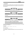
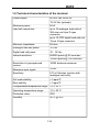
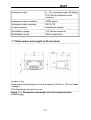
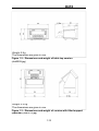
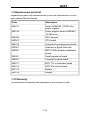
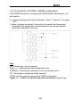
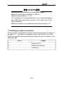
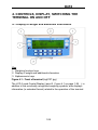
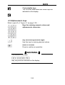
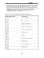
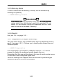
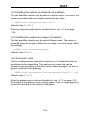
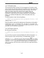
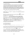
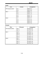
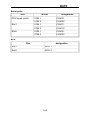
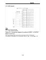
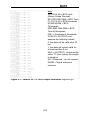
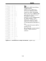
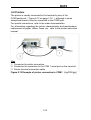
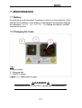
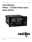
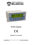
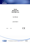
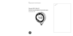
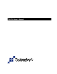
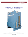
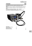
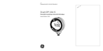
D410 Terminal
Use and maintenance manual
Code 813711
EDITION 30 May 2001
D410
Index
1. GENERAL
1.1 Declaration of conformity
1.2 Foreword
1.3 Symbols
1.4 Documentation
1.5 Description of the terminal
1.6 Technical characteristics of the terminal
1.7 Dimensions and weight of the terminal
1.8 Obtaining technical assistance
1.9 Replacement parts list
1.10 Warranty
1-5
1-5
1-6
1-8
1-9
1-9
1-10
1-11
1-13
1-14
1-14
2. SAFETY INSTRUCTIONS
2.1 Prohibited uses
2.2 Regulations
2.3 Prescriptions of use
1-15
1-15
1-15
1-15
3. DELIVERY AND INSTALLATION
3.1 Connection of the terminal to the electrical supply line
3.2 Connection of the terminal to the platform scale
3.2.1 Equipotentiality between the terminal and the platform scale
3.2.2 Connection of analogue load cells
3.2.3 Connection of digital load cells
3.3 COM1 serial port connection
3.4 COM2 serial port connection
3.4.1 Connection of COM2 in RS232 configuration
3.4.2 Connection of COM2 in RS422 configuration
3.4.3 Connection of COM2 in RS485 configuration
3.5 Analogue output connection
3.6 Input/Output connection
1-17
1-18
1-19
1-20
1-20
1-21
1-22
1-23
1-23
1-24
1-25
1-26
1-27
4. CONTROLS, DISPLAY, SWITCHING THE TERMINAL ON AND OFF
4.1 Display of weight and additional information
4.1.1 Selection display symbols
4.2 Weighing function keys
4.3 Alphanumeric keys
4.4 Switching the terminal on and off
1-29
1-29
1-30
1-31
1-33
1-34
5. USE OF THE TERMINAL
5.1 General
5.1.1 Using the keys to navigate the menus
5.1.2 Entering numeric data (Editor)
5.1.3 Entering alphanumeric data
5.1.4 Shortcut keys
5.2 User menu
5.2.1 User menu tree
5.2.2 Adjusting the contrast
5.2.3 Changing the date and time
5.2.4 Weight display
5.2.5 Memory status
5.2.6 Reprint
1-37
1-37
1-37
1-38
1-38
1-40
1-40
1-40
1-42
1-42
1-42
1-45
1-45
1-3
D410
5.2.7 Diagnostics (for digital scale only)
5.2.8 Setting the outputs as Setpoints (if enabled)
5.2.9 Setting the outputs as ranges (if enabled)
5.2.10 Generic code
5.2.11 Product code
5.2.12 Product code list
5.2.13 Preset tares
5.2.14 Preset tare list
5.2.15 Progressive number
5.2.16 Coefficient Management
5.2.17 Totals management
5.3 Printing weighing data
5.3.1 Weighing data reprint
5.4 Operating modes
5.4.1 Standard operation
5.4.2 Sum weighing operation
5.4.3 Loading extraction operation
5.4.4 Unloading extraction operation
5.5 MPP operation
1-45
1-46
1-46
1-46
1-47
1-47
1-48
1-48
1-49
1-49
1-50
1-52
1-53
1-54
1-54
1-54
1-54
1-55
1-55
6. OPTIONS
6.1 4 I/O board
6.2 BCD parallel 5V
6.3 Calculator BCD
6.4 Parallel 24V source current BCD (positive common)
6.5 Serial port expansion board
6.6 MPP memory expansion boards
6.6.1 Memory capacity
6.6.2 Operation
6.6.3 Disabling MPP
6.6.4 Checking memorised weight data
6.7 12-24Vac-dc input power supplier
6.8 Printers
1-57
1-60
1-61
1-63
1-65
1-68
1-71
1-71
1-71
1-72
1-73
1-74
1-76
7. MAINTENANCE
7.1 Battery
7.2 Changing the fuses
1-77
1-77
1-77
8. TROUBLESHOOTING
8.1 Malfunctions
8.2 Error messages
1-79
1-79
1-80
1-4
D410
1. GENERAL
1.1 Declaration of conformity
DECLARATION OF CONFORMITY
Manufacturer:
SOCIETÀ COOPERATIVA
BILANCIAI
Address:
Via S. Ferrari, 16
41011 Campogalliano (MO)- Italy
declares that the product
electronic terminal model:
D410
with the options
all those described in this manual
conforms to:
standards EN45501, EN50081-1 in accordance with the
requirements of Directive 89/336 EEC (electromagnetic compatibility)
standard EN60950 in accordance with the requirements of Directive
73/23 EEC (low voltage directive)
The terminal is also suitable for the creation of approved
non-automatic weighing instruments with "CE Type Approval
Certificate" in conformance with the requirements of Directive 90/384
EEC.
The product bears the CE marking.
Campogalliano, 24 July 2000
Technical Director
Eng. Luciano Diacci
Declaration drafted in conformance with EN45014.
1-5
D410
1.2 Foreword
The aim of this manual is to provide the operator, through the use of
text and illustrations, with essential information regarding the
installation, safe operation and maintenance of the weighing system.
This manual must be kept in a safe place where it is readily available
for consultation. Always observe the instructions contained in the
manual!
The safe operation of the system is the responsibility of the operator,
who must have a thorough knowledge of the system.
The user is responsible for ensuring that the installation conforms to
the applicable regulations.
The equipment must be installed by specialised personnel who have
read and understood this manual.
"Specialised personnel" means any personnel who, by virtue of the
training they have received and their professional experience, have
been explicitly authorised by the "System safety supervisor" to install,
operate and maintain the system.
In the event of any problems, contact your nearest Service Centre.
Any attempt on the part of unauthorised personnel to dismantle or
modify the terminal is prohibited; any such attempt shall invalidate the
warranty and release the manufacturer from all liability for any injury
or damage.
The alteration or removal of the data plates and seals is strictly
prohibited; check that all plates and seals are present and legible, if
not contact After-Sales Service.
The manufacturer shall not be liable for any damages caused by
incorrect handling of the terminal.
The information and illustrations contained in this manual were up to
date at the time of publication.
The Manufacturer is committed to a policy of continuous product
improvement and system components may therefore be subject to
modification.
All the technical information contained in this manual remains the
exclusive property of the manufacturer and may not be divulged to
third parties.
No part of this document maybe reproduced or transmitted in any
1-6
D410
form, including publication in computerised form or on the World Wide
Web, without the express written permission of the manufacturer.
This manual may not be used for purposes other than those directly
related to the installation, operation and maintenance of the terminal.
In order to more clearly illustrate certain maintenance or adjustment
operations, some of the illustrations in this manual show the weighing
system with the safety guards removed. Under no circumstances may
the system be operated in these conditions. Do not operate the
system in these conditions under any circumstances whatsoever, but
remove the safety guards for the time strictly required to carry out the
required repairs or maintenance then fit them back in place.
1-7
D410
1.3 Symbols
Below is a list of the symbols used in this manual to alert the reader to
the various hazards associated with the operation and maintenance of
the instrument.
DANGER
Denotes an operation or procedure where failure to observe
the instructions will result in death or serious injury.
CAUTION
Denotes an operation or procedure where failure to observe
the instructions could result in minor injury or damage to the
instrument.
WARNING
Information or instructions on how the system is to be
operated correctly in order to maximise its service life or
prevent loss or damage of programmed data or to optimise
operation with regard to metrological standards.
Text and messages displayed on the terminal are printed in this manual
using special characters.
Messages:
Display messages appear like this.
Menu pathways:
2°F>OTHER>MENU>Contrast.
The character > indicates the transition from one menu option to the
next.
1-8
D410
1.4 Documentation
This manual is accompanied by a CD-ROM that primarily contains
information about the installation of the terminal.
Here you will find information on how to interface the terminal with a PC
and PLC.
1.5 Description of the terminal
The model D410 digital weight indicator allows highly accurate and
reliable weighing. This terminal is designed to facilitate dialogue with the
operator through the alphanumeric keypad and graphic display, which, in
addition to being extremely easy to use, has facilities for changing the
shape and size of the display characters to suit various conditions of
use. The D410 terminal provides a wide range functions, which,
combined with the possibilities for expansion, allow for easy interfacing
with external equipment.
Some of the main features of the terminal:
facility for connection to a scale with analogue load cells (up to 12 x
350 ohm load cells)
facility for connection to a scale with digital load cells (up to 12 CPD
load cells)
two RS232/422/485 serial ports
analogue output of 0-10V or 0(4)-20 mA
2 inputs and 2 relay outputs
110/230 Vac power
specific operating modes that can be selected by the operator
facility for connection to a tally roll printer, document printer or
labelling machine
management of totals files associated with alphanumeric codes
quick customisation of keypad and messages
1-9
D410
1.6 Technical characteristics of the terminal
Power supply
85-265 Vac 50/60 Hz
12-24 Vdc (optional)
Maximum power:
50 W
Load cell connection:
up to 12 analogue load cells of
350 ohm via 9-pin D-type
connector
up to 12 CPD digital load cells via
15-pin D-type connector
Minimum impedance:
29 ohm
Analogue load cell power:
10 Vdc
Digital load cell power:
10 - 18 Vdc
Internal resolution:
500000 points @ 25 conv/sec
120000 points @ 100 conv/sec
Resolution in type-approved
version:
10000 divisions maximum
Maximum input signal:
23 mV
Sensitivity:
0.75 uV/division (version with
analogue load cells)
Full scale stability:
< 5 ppm/°C
Zero stability:
< 5 ppm/°C
Compensated temperature range: -10 + 40 °C
Operating temperature range:
-10 + 50 °C
Protection class:
IP20
Humidity:
85 % @ 40°C
1-10
D410
Analogue output:
0 - 10 V (minimum load 100 kohm)
0 (4)-20 mA (maximum load
250ohm)
Analogue output resolution:
10000 points
Analogue output precision:
0.05 % FS
Output contacts:
mechanical contact
Switchable voltage:
110 Vac/dc maximum
Switchable current:
200 mA maximum
1.7 Dimensions and weight of the terminal
Weight: 2 Kg
Dimensions of panel space for rack mounting: 200 mm x 104 mm (base
x height)
The dimensions are given in mm.
Figure 1.1 - Dimensions and weight of rack-mounted version
(cbd0010.jpg)
1-11
D410
Weight: 2 Kg
The dimensions are given in mm.
Figure 1.2 - Dimensions and weight of table top version
(cbd0009.jpg)
Weight: 2.5 Kg
The dimensions are given in mm.
Figure 1.3 - Dimensions and weight of version with tilted support
(optional) (cbd0012.jpg)
1-12
D410
1.8 Obtaining technical assistance
In the event of any operating faults requiring the intervention of
specialised technicians, contact the manufacturer or your nearest
Service Centre. To enable us to deal with your request swiftly, always
quote the serial number of your terminal, which can be found on the seal
label. Also provide information about the system in which the terminal is
installed.
1-13
D410
1.9 Replacement parts list
Replacement parts can ordered directly from the manufacturer or from
your nearest Service Centre.
Code
Description
460727
Series D400/800 110/230 Vac
power supplier
460740
Power supplier series D400/800
12-24Vdc-ac
290389
D410 keypad
403941
CPU board
460728
Converter for analogue load cells
403961
Interface or digital load cells
403981
MPP FLASH memory expansion
board
403991
Serial expansion board
404001
4 inputs/4 outputs board
404011
BCD TTL or calculator board
404012
BCD 24V source board
527313
Battery
460729
Display
1.10 Warranty
The conditions of warranty are stipulated in the contract of sale.
1-14
D410
2. SAFETY INSTRUCTIONS
2.1 Prohibited uses
The instrument you have purchased is a weighing system and has been
designed and manufactured as such. The instrument is primarily
intended for the weighing of goods.
It is forbidden to use the terminal without taking the necessary
precautions for safe use.
Use of the terminal in places with potentially explosive atmospheres
or in areas where there is a risk of fire is strictly prohibited.
Any other use shall only be permitted if expressly authorised by the
Manufacturer.
2.2 Regulations
The operating conditions for the electronic terminal are subject to the
regulations in force in the country in which the terminal is used. All use
of the terminal in conditions which do not comply with these regulations
is prohibited.
2.3 Prescriptions of use
Strictly comply with the instructions in this manual during use.
In the event of any discrepancy between the information in this
manual and the instrument purchased, contact your Dealer or the
Manufacturer's After-Sales Service for clarification.
Always observe the indications given on the warning and danger
plates on the terminal.
Check that all the safety guards are in place and that the connection
cables are in good condition and connected correctly.
Check that the terminal is connected to an electrical outlet socket
equipped with an effective earth connection. Make sure that the line
complies with the applicable regulations. Check that there is no
difference in potential between the earth and neutral conductors.
If the terminal is to be connected to other devices (e.g. a computer),
these devices must be disconnected from the electrical supply before
connection to the terminal.
1-15
D410
All maintenance and/or repairs must be carried out by authorised
personnel only.
Always disconnect the terminal from the electrical supply and wait a
few minutes before accessing the internal components.
1-16
D410
3. DELIVERY AND INSTALLATION
Key
1. 9-pin male connector (JBIL) for platform scale connection (15-pin
male for digital load cells)
2. 9-pin female serial port connector (JCOM 1) for printer connection
3. 9-pin female serial port connector (JCOM 2) for connection of
various devices
4. Data plate indicating voltage, frequency and fuse types
5. Analogue output connection terminals (JVI)
6. Input/Output connection terminals (JI/O)
7. Earth screw
8. Male 3-pin connector for power supply connection
9. Fuses
10. ON/OFF switch
11. Expansion slot 2
12. Expansion slot 1
Figure 3.1 - Rear of terminal (log0103.jpg)
1-17
D410
3.1 Connection of the terminal to the electrical supply line
DANGER
Check that:
The voltage and frequency of the electrical supply line
corresponds to the indications on the warning plate on the
rear of the terminal (see point 4 Figure 3.1 on page 1-17 );
the mains outlet socket to which the terminal is connected
is equipped with an earth;
the warning and danger signs are present and legible;
failing this, notify your maintenance personnel or contact
our Assistance Service directly;
For the correct connection of the terminal to the electrical supply line,
proceed as follows:
plug the 3-pin connector of the power lead into the connector on the
rear if the terminal;
insert the plug of the power lead into the correct mains outlet socket.
The terminal complies with the European Directive for electromagnetic
compatibility, however it is good practice to provide a separate power
supply line for the terminal.
1-18
D410
WARNING
Do not route the terminal connection cables alongside power
cables as these could cause disturbances that interfere with
the correct operation of the terminal. Only use the connection
cable supplied with the terminal. If the cable supplied is too
short, do not attach an extension lead but contact the
Manufacturer.
3.2 Connection of the terminal to the platform scale
The terminal is normally supplied with a pre-wired cable for connection
to the platform scale. The female connector on this cable should be
plugged into the male 9/15-pin connector (JBIL) on the rear of the
terminal (see point 1 Figure 3.1 on page 1-17 ). The connection
method may vary according to the type of transducer on the platform
scale (analogue or digital).
WARNING
The cable screen should always be connected to the metal
cap of the 9/15-pin connector. Do not route the scale
connection cable alongside power cables.
1-19
D410
3.2.1 Equipotentiality between the terminal and the platform
scale
Check that a condition of equipotentiality exists between the metal parts
of the terminal and the platform scale.
If in doubt, connect the terminal and the scale using a earth wire of at
least 6mm² using the earth screw on the rear of the terminal (see point 7
Figure 3.1 on page 1-17 ).
The cables required for this connection are to be provided by the
customer.
3.2.2 Connection of analogue load cells
The diagram below shows the pinout for the JBIL connector for
connection to scales with analogue load cells.
Key
NC = Reserved - do not connect
SIG + = Signal +
SIG - = Signal EX + = Excitation +
EX - = Excitation SENSE + = SENSE signal +
SENSE - = SENSE signal -
Figure 3.2 - Pinout for the JBIL connector for connection to scales
with analogue load cells (log0001.gif)
1-20
D410
3.2.3 Connection of digital load cells
Connection to digital load cells is by RS485 serial line using a screened
cable with 6 conductors. The diagram below shows the pinout of the
JBIL connector for connection to platform scales with digital load cells.
Key
EX + = Excitation +
EX - = Excitation DATA +/- = Bidirectional data
transmission line
NC = Reserved - do not connect
Figure 3.3 - Pinout of JBIL connector for connection to scales with
digital load cells (log0002.gif)
Pins carrying the same signals may be connected in parallel.
1-21
D410
3.3 COM1 serial port connection
The terminal has an RS232 serial port (COM1) with a 9-pin female
connector located on the rear panel (see point 2 Figure 3.1 on page
1-17 ); the diagram below shows the pin connections for this port.
Key
NC = Reserved - do not connect
RX232 = Data reception
TX232 = Data transmission
CTS232 = Clear to send
RTS232 = Request to send
GND = Signal ground
Figure 3.4 - Standard serial port connector (9-pin female D-type)
(log0003.gif)
CAUTION
Operating limits stipulated by the standard RS232:
Maximum transmission distance = 15 m
Maximum line voltage = ± 12 Vdc
For connection to external devices, use a screened cable
and connect the screen to the metal cap of the 9-pin
connector.
1-22
D410
3.4 COM2 serial port connection
The terminal has second serial port, which can be configured for RS232,
RS422 or RS485 data transmission standards. The serial port (COM2)
has a 9-pin female connector (see point 3 Figure 3.1 on page 1-17 ).
3.4.1 Connection of COM2 in RS232 configuration
For the connection of external devices, refer to the pinout diagram in
Figure 3.5 on page 1-23 :
Key
NC = Reserved - do not connect
RX232 = Data reception
TX232 = Data transmission
GND = Signal ground
Ri = Termination resistance
inside terminal
NOTE: the free pins are
reserved for RS422 - RS485
connection
Figure 3.5 - COM2 serial port connector (9-pin female D-type)
(log0004.gif)
CAUTION
The RS232 operating limits are indicated in par. 3.3 on page
1-22 .
1-23
D410
3.4.2 Connection of COM2 in RS422 configuration
Key
NC = Reserved - do not connect
RX422 +/- = Data reception
TX422 +/- = Data transmission
TERMIN = Termination
resistance to be connected to
pin 6
Ri = Termination resistance
inside terminal
NOTE: the free pins are
reserved for RS232 connection
Figure 3.6 - Example of RS422 serial port connection (log0005.gif)
CAUTION
Operating limits stipulated by the standard RS422:
Maximum transmission distance = 1200 m
Maximum line voltage = +/- 7V
For connection to external devices, use a screened twisted
pair cable and connect the screen to the metal cap of the
9-pin connector.
1-24
D410
3.4.3 Connection of COM2 in RS485 configuration
If the COM2 serial port is configured for RS485 data transmission, you
will need to:
connect together pins 9 and 6 and pins 1 and 7 ( Figure 3.7 on page
1-25 )
place a jumper across pin 6 and pin 8 to connect the termination
resistance; this operation is to be carried out on the first and last
terminals connected in the line
Key
NC = Reserved - do not connect
DATA +/- = Bidirectional data transmission line
TERMIN = Termination resistance to be connected to pin 6
Ri = Termination resistance inside terminal
NOTE: the free pins are reserved for RS232 connection
Figure 3.7 - Pinout for RS485 serial port connection (log0006.gif)
1-25
D410
CAUTION
Operating limits stipulated by the standard RS485:
Maximum transmission distance = 1200 m
Maximum line voltage = +/- 7V
For connection to external devices, use a screened twisted
pair cable and connect the screen to the metal cap of the
9-pin connector.
Maximum number of terminals that may be connected = 16
3.5 Analogue output connection
The connector JVI located on the rear of the terminal (point 5 Figure 3.1
on page 1-17 ) provides an analogue output in the forms 0-10 V and
0(4)-20 mA galvanically separated; the connection pinout is given in the
following table.
Pin n°
Signal
1
Output 0-10 V
2
Output 0(4)-20 mA
3
Common
1-26
D410
CAUTION
Technical characteristics:
Resolution= 10000 points
Precision = 0.05 % FS
Minimum voltage output load = 100 kohm
Minimum current output load = 250 ohm
3.6 Input/Output connection
The terminal board JI/O on the rear of the instrument (point 6 Figure 3.1
on page 1-17 ) provides input and output contacts; Figure 3.8 on page
1-27 contains the pinout diagram.
Key
Pi = Part inside terminal
Pe = Part outside terminal
Figure 3.8 - JI/O terminal board for Input/Output connections
(log0008.gif)
1-27
D410
CAUTION
Technical characteristics:
Input:
Maximum input voltage = 24Vdc
Maximum input current = 5mA
The inputs can be controlled by a mechanical contact or by
an NPN-type transistor (negative common)
Output:
mechanical voltage-free contact
Maximum switchable voltage = 110 Vac/dc
Maximum switchable current = 200 mA
I/O refresh time = 1/10 s
DANGER
When the weighing system is installed in complex plants that
can represent a danger hazard for operators, enlist the
assistance of specialised personnel to perform several
manoeuvres without load in order to acquire the experience
necessary to work in safety.
1-28
D410
4. CONTROLS, DISPLAY, SWITCHING THE
TERMINAL ON AND OFF
4.1 Display of weight and additional information
Key
1. Weighing function keys
2. Display of weight and additional information
3. Alphanumeric keys
Figure 4.1 - Front of terminal (log0127.jpg)
The LCD (Liquid Crystal Display) (point 2 Figure 4.1 on page 1-29 ), in
addition to the universally recognised weighing symbols, also displays
information (in extended format) related to the operation of the terminal.
1-29
D410
Listed below are the weighing symbols displayed and their meanings:
Weight stable symbol
Indicates that the weight value displayed is stable
and thus may be printed and/or transmitted.
Centre zero symbol
Indicates that the weight on the scale is near to
zero i.e. within -1/4 + 1/4 of a division.
Tare symbol
Indicates the presence in memory of an acquired
tare value.
Preset tare symbol
Indicates that a tare value has been entered from
the keypad.
Gross weight symbol
Gross weight symbol with units of
measurement in lb (as alternative to B)
This symbol only illuminates when the unit of
measurement is "lb" (pounds).
Minimum weighment
Net weight symbol
Weighing range indication for multi-extension
(ME) instruments
4.1.1 Selection display symbols
Weight indication
Below preset lower limit.
1-30
D410
Weight indication
Within the preset upper and lower limits.
Weight indication
Above the preset upper limit.
4.2 Weighing function keys
Refer to point 2 of Figure 4.1 on page 1-29 :
Zero-set weight
pressing this key resets the weight indication only
if the following condition are satisfied:
the weight value must be within the -1% ÷ +3%
range of the weighing capacity for terminals
subject to legal verification or ± 50% for other
terminals;
the weight must be stable;
no tare must be entered.
Enter/cancel tare
On pressing this key, the weight on the scale is
acquired as the tare value, provided the following
conditions are satisfied:
the weight must be stable;
the weight must have a positive value;
the weight must not exceed the maximum
capacity.
The display illuminates the symbols
and
.
On MD terminals, the weight indication will be
displayed using the division of the lower range. On
ME terminals, the net weight will be displayed
using the division of the range in within which it
falls.
1-31
D410
On pressing
again, the tare will be cancelled
and the terminal resumes display of the gross
weight.
Enter/display tare
Pressing this key allows you to enter a tare value
using the numeric keys on the keypad ( par. 4.3
on page 1-33 ). To change a preset tare value
see par. 5.2.13 on page 1-48 .
On completion of the operation, the display will
show the net weight and tare values and illuminate
the symbols
and
. The entered tare
value will be automatically rounded off to the
nearest scale division. On MD terminals, the net
weight will be displayed using the division of the
range within which the net weight value falls, while
on ME terminals, the net weight division shall be
that of the range within which the gross weight
falls. On MD terminals, the maximum preset tare
value is limited to the maximum capacity of the
first weighing extension (indicated on the
metrological data plate).
Print and/or send
Allows a weighing option to be requested.
Consequently forces a weighing data printout
and/or serial transmission of a string of data via
the configured port.
1-32
D410
Customizable keys
The functions associated with these keys are
indicated on the display.
4.3 Alphanumeric keys
Refer to point 3 of Figure 4.1 on page 1-29 :
Keys for entering numeric values and
alphanumeric characters
Key for entering decimal digits
Use this key for entering decimal values.
Enter or confirm
Press to confirm an operation.
WARNING
The function of the keys
may vary and are indicated on the display.
1-33
D410
4.4 Switching the terminal on and off
Key
1. ON/OFF switch
Figure 4.2 - On/Off switch (log0105.jpg)
DANGER
Before switching on the terminal, check that the safety
guards are in place and in good working order.
If the terminal is wall mounted on an electrical panel, there
must be a main switch that disconnect powers to the entire
panel.
To identify this switch, contact your internal maintenance
manager.
1-34
D410
Press the switch on the rear of the terminal (see point 1 Figure 4.2 on
page 1-34 ) to position:
I
O
to switch on the terminal;
to switch it off
On power on, the display will show the Manufacturer's logo and the type
of operation for which the terminal is enabled (see par. 5.4 on page
1-54 ).
Wait for the LOCK indication to appear (terminals subject to metrological
verification only).
If on completion of the operation the display shows a value other than
zero , press
to zero-set the reading.
If the display is not zero-set on pressing the key:
check that the platform scale is in fact unloaded. If not, unload the
scale, switch off the terminal and then switch it on again;
If the problem persists, contact your Service Centre.
1-35
D410
1-36
D410
5. USE OF THE TERMINAL
5.1 General
5.1.1 Using the keys to navigate the menus
The numeric keys
described in par. 4.3 on
page 1-33 and the customisable keys
e
par. 4.2 on page
1-31 can be used to navigate the programming menus.
From the normal weight display condition, you can access the menus by
pressing
to select the option 2°F . Now use the other keys to select
the next option. A maximum of 6 functions are available on the bar of the
shortcut keys. By pressing the key in correspondence with the indication
OTHERS you can switch to other functions managed by the terminal. The
arrow keys ↑ , ↓ , → , ← allow you to move respectively up, down,
right and left.
By pressing SELECT you can select the required option or enter a
submenu.
The keys # and \\ allow you to change the way the menu pathway is
displayed : # extended pathway, \\ pathway expressed numerically.
Selecting ESC returns you to the previous menu level. By pressing ESC
repeatedly you can therefore exit through the menus to return to the
normal weight display mode. Form here on in this manual, the
instructions will only indicate the pathway without referring to the specific
keys to be pressed. For example, the instruction on how to change the
contrast will be given as follows:
2°F>CONTR>+ o ->SAVE>ESC
1-37
D410
5.1.2 Entering numeric data (Editor)
Numeric values may be entered as follows:
select the function for which you wish to enter the value (preset tare,
settings, range...); the display will show the selected function with the
value currently stored in memory;
enter the value using the numeric keys ( par. 4.3 on page 1-33 )
press
to confirm the value and return to the previous menu.
5.1.3 Entering alphanumeric data
Alphanumeric data may be entered as follows:
Select a function for which an alphanumeric value may be entered
(e.g. the generic code);
press the keys corresponding to the letters you want to enter;
press
to confirm.
bear in mind that:
pressing the same key repeatedly displays each of the letters, the
number and the special characters associated with that key in
sequence;
to confirm the letter displayed, simply press, simply press another
alphanumeric key;
to enter two consecutive letters using the same key, wait a second
before pressing the key again: the correct position will be indicated by
the cursor;
1-38
D410
prolonged pressure on a key will display all the characters associated
with that key. By moving left and right with the keys → and ←you
can select the character you wish to enter. The selected character is
displayed in reverse video. Confirm the selection by pressing OK. To
toggle between upper and lower case letters, press the key in
correspondence with the indication CAPIT/SMALL.
Below is a list of the characters associated with each key:
Alphanumeric keys
Characters
,-+;*/=%><
0 . : ? ! ( )¿ ¡ '
(blank) 1 £ $ @ & ª º
ABC2âäàåÄÅçÇ
DEF3èêëèÈæÆ
GHI4ïîìí
JKL5
MNO6ôöòóÖñÑ
PQRS7ß
TUV8üûùúÜ
WXYZ9ÿ
1-39
D410
5.1.4 Shortcut keys
During installation, User menu functions may be assigned to shortcut
keys. In this way the user can access the required function more rapidly.
For example, to access the function Product Code , the user will not
have to press
...MENU>Data Management>Code Management>Product Code
but simply press PROCOD
The abbreviations that appear on the display may be customised during
installation. For this reason, the abbreviations related to the shortcut
keys that appear in brackets alongside or below the pathways described
in the following paragraphs may have been modified by the installer. Ask
your installer for a list of the abbreviations and their meanings.
The pathways themselves may also vary according to the number of
files and the shortcut keys assigned during installation. In this case the
MENU key may be accessed by pressing 2ºF and OTHERS.
5.2 User menu
5.2.1 User menu tree
The User menu tree expanded to the third level is reported below. For
details of the various functions, refer to the subsequent paragraphs
(5.2.2 to 5.2.17).
1-40
D410
Data management
Codes management
Generic code
Product Code
Product Code List
Range
Range 01
Range 02
Range 11
Range 12
Range 13
Range 14
Range 21
Range 22
Range 23
Range 24
Setpoint
Setpoint 01
Setpoint 02
Setpoint 11
Setpoint 12
Setpoint 13
Setpoint 14
Setpoint 21
Setpoint 22
Setpoint 23
Setpoint 24
Display MPP data
Preset tares
Entering
Preset tares list
Progressive N.
Coefficient management
Coefficient
Operation
Rounding
Totals management
General Total
Partial Total
Product Code Total
Generic Code Total
MPP operation
De-activated
With memory
With printer
Display
15mm digits
30mm digits
Selection
Extraction
Display tare
Contrast
Memory status
Reprint
Date Time
Diagnostics
1-41
D410
5.2.2 Adjusting the contrast
To adjust the contrast of the display, follow the pathway:
...>MENU>Contrast
(Shortcut key CONTR).
By pressing + or - you can adjust the contrast. To save the new setting
in memory press SAVE .
5.2.3 Changing the date and time
Follow the pathway:
...>MENU>Date Time
(Shortcut key DATIME).
To change quickly from summer to winter time press + or - 1 hour,
alternatively use the option CHANGE .
5.2.4 Weight display
You can change the way the weight value is displayed on the terminal.
The current weight display mode will depend on the operation type set
during installation (see par. 5.4 on page 1-54 ).
To select the display mode follow the pathway:
...>MENU>Display
(Shortcut key VISUAL).
The possible display modes are:
15mm digits
The display shows the gross weight (or net) and the weighing
symbols.
30mm digits
The display shows the weight in 30 mm high digits and the weighing
symbols.
1-42
D410
Selection
In addition to the weight and the usual weighing symbols, the display
shows one of the following symbols
(see par. 4.1.1 on
page 1-30 ).
To set the range, press DRANGE , select the values with SELECT and
enter the numerical values using the number keys ( par. 4.3 on page
1-33 ).
WARNING
The display range described here is independent of the
range associated with the outputs (see par. 5.2.8 on page
1-46 and par. 5.2.9 on page 1-46 .
Display tare
In addition to the usual weighing symbols, the terminal can also
simultaneously display the net weight and the tare (if present).
The following indications are displayed:
If a tare has been entered by pressing
were not set during installation:
and multiple tares
Tare: tare value + unit of measurement
The indications
and PT will be illuminated.
If the tare was acquired by pressing
not been set:
and multiple tares have
Tare: tare value + unit of measurement
The indications
and T will be illuminated.
If the tare is preset ( par. 5.2.13 on page 1-48 and multiple tares
have not been set:
Tare C: preset tare value + unit of measurement
The indications
and PT will be illuminated.
1-43
D410
NOTE: the indication Tare C indicates that the tare displayed is a
"coded" tare to which a numerical code has been assigned ( par.
5.2.12 on page 1-47 ).
If multiple tares were set during installation:
Tare T: acquired tare value + unit of measurement
Tare 1 PT: preset tare 1 value + unit of
measurement
Tare 2 PT: preset tare 2 value + unit of
measurement
Or
Tare C PT: preset tare value + unit of
measurement
Tare 1 PT: preset tare 1 value + unit of
measurement
Tare 2 PT: preset tare 2 value + unit of
measurement
Or
Tare PT: "non coded" tare value + unit of
measurement
Tare 1 PT: preset tare 1 value + unit of
measurement
Tare 2 PT: preset tare 2 value + unit of
measurement
The indications
and PT will be illuminated.
NOTE: Tare 1 and Tare 2 may also be recalled via numeric
code ( par. 5.2.13 on page 1-48 ).
Extraction
This display mode is only possible if loading or unloading extraction
operating mode is selected (see par. 5.4.3 on page 1-54 and par.
5.4.4 on page 1-55 ).
The display shows the gross weight, the extracted weight and the
weighing symbols.
1-44
D410
5.2.5 Memory status
If there is insufficient free memory, memory can be recovered by
following the pathway:
...>MENU>Memory status
CAUTION
The memory recovery operation may require a few minutes
during which time the terminal cannot be operated. Do not
switch off the terminal during this operation as this could
result in the loss of the data in memory.
5.2.6 Reprint
See par. 5.3.1 on page 1-53 .
5.2.7 Diagnostics (for digital scale only)
This user menu item is only available when there are digital cell errors (
par. 8.2 on page 1-80 ). It allows you to identify what caused the error.
Follow this path:
...>MENU>Diagnostics
If the instrument is not subject to calibration checks, CONT can be
pressed to display the measured weight despite the error.
Remember that this can only be done in the case of serial number errors
or ones due to non-configured digital cells.
The error message will reappear when the terminal is powered again
unless the cause of the error is eliminated.
1-45
D410
5.2.8 Setting the outputs as Setpoints (if enabled)
The two available outputs may be used in setpoint mode. In this way, the
output is activated when the weight reaches the set value.
...>MENU>Data management>Set Point
(Shortcut key SETPNT ).
Enter the required weight values as described in par. 5.1.2 on page
1-38 .
5.2.9 Setting the outputs as ranges (if enabled)
The two available outputs may be used in Range mode. The output is
activated when the weight is within the set range; to set the range, follow
the pathway:
...>MENU>Data management>Range
(Shortcut key RANGE ).
5.2.10 Generic code
This is an alphanumeric code with a maximum of 8 characters that can
be printed and/or transmitted. The maximum of codes that can be
entered varies according to the other types of data managed. To enter a
generic code follow the pathway:
...>MENU>Data management>Code management>Generic code
(Shortcut key GCCOD ).
Enter the alphanumeric code as described in par. 5.1.3 on page 1-38 .
If the value of the generic code = empty space, it will no longer appear in
the printout and will not be used for totalization.
1-46
D410
5.2.11 Product code
The terminal provides functions for the management of product codes,
each of which may be associated with an alphanumeric description that
can be printed and/or transmitted along with the weight. The product
code is a numeric code with a maximum of 6 digits, while the
alphanumeric description may be up to 20 characters long. The
maximum of codes that can be entered is defined in the installation
phase. It is variable and depends on which other data need to be
managed.
To enter a product code, follow the pathway:
...>MENU>Data management>Code management>Product code
(Shortcut key PROCOD ).
Enter the product code and the alphanumeric description as described
respectively in par. 5.1.2 on page 1-38 and par. 5.1.3 on page 1-38 .
If the product code is set to 0 (zero) during weighing operations, it will be
excluded from all totalization operations.
5.2.12 Product code list
By following the pathway:
...>MENU>Data management>Code management>Product code
list
you can call up a product code and display the relative description. To
call up a product code, press the key in correspondence with the
indication PROCOD , enter the numeric code and press
to confirm.
If a printer is connected, by pressing the key in correspondence with the
indication SUMMAR , you can print the data relative to a single product
code or summary of all the product codes within the range specified by
the operator.
1-47
D410
5.2.13 Preset tares
In addition the management of tares acquired from the weight present
on the scale and tares entered from the keypad, the terminal also
manages an archive of preset tares containing a number of values
difined during the installation phase. Each value can be recalled by way
of a 4 digit numeric code. Preset tares, once recalled by entering the
relative code, are automatically subtracted from the weight on the scale.
Preset codes may be entered by following the pathway:
...>MENU>Data management>Preset tare> Entering
(Shortcut keys TAREC and TARCn where n= 1,2 if multiple tares were set
during installation)
Select the tare type, enter the code number and press
If necessary, enter the tare value.
to confirm.
The value TARE 2 can be multiplied by a number, designated the
Packs number , which may be entered from the keypad to obtain a
sum tare value (e.g. the sum of the tares of n containers of the same
weight). The Packs Number can be entered directly from the shortcut
key bar by pressing the key in correspondence to the indication PACKSN
. The functions TARE 1 and TARE 2 , together with the Packs Number
, allow weighing of products with both primary (e.g. pallets) and
secondary (e.g. boxes) packaging.
5.2.14 Preset tare list
By following the pathway:
...>MENU>Data management>Preset tare>Preset tare list
you can call up a tare code and display the corresponding tare value. To
recall a tare code, press the key in correspondence to the indication
TAREC , enter the numeric code and press
to confirm.
If a printer is connected, on pressing the key in correspondence to the
indication SUMMAR you can print the data relative to a single tare code or
a summary of all the tare codes within a specified range.
1-48
D410
5.2.15 Progressive number
The terminal manages a 6-digit progressive number used to count the
number of weighing operations performed: this value starts from 1 and is
automatically increased by one unit after each print and/or weighing
operation (and thus indicates the value of the next print or weighing
operation). To change the progressive number, follow the pathway:
...>MENU>Data management>Progressive
(Shortcut key PROG.N )
If the progressive number is set to 0 (zero), it will not be incremented
and not be printed.
5.2.16 Coefficient Management
This function can be of use when the unit of measurement needs to be
converted. for example, you can calculate the number of litres if the
specific weight and overall weight of a liquid are known.
Follow the following path to access this menu:
...>MENU>Data Management>Coefficient Management
(COEF rapid key)
Enter the required coefficient, then select the required type of
operation (multiplication or division) and the rounding value for the
result. This latter is just a numerical value without unit of measurement.
1-49
D410
5.2.17 Totals management
The terminal provides functions for totalling the weighing data
associated with the various codes. The totalization operation consists of
adding the current weight value to the sum of the previous weights and
increasing by one the number of weighing operations. To access the list
of available totals, follow the pathway:
...>MENU>Totals management
(Shortcut key TOTALS )
General totals
These totalization functions provide general totals for the gross
weight (if enabled during installation), net, tare and number of
weighing operations independently of any associated codes. The data
can be obtained using the following functions:
...>MENU>Totals management>General total
(Shortcut key GENTOT )
...>MENU>Totals management>Partial total
(Shortcut key PARTOT )
PRINT prints selected value
RESET resets the total
1-50
D410
Totals by code
Saves the net weight values and number of weighments associated
with a product code and generic code. The data can be accessed
through the following functions:
...>MENU>Totals management>Product code total
(Shortcut key PROTOT )
...>MENU>Totals management>Generic code total
(Shortcut key GCTOT )
PRINT prints the selected total
SUMMAR prints the list of all the codes
RESET resets the total
PROCOD allows you to select another product code
GCCODE allows you to select another generic code
1-51
D410
5.3 Printing weighing data
The printer is normally connected to the terminal by way of the COM1
serial port ( par. 6.8 on page 1-76 ).
Printouts are obtained by pressing
. Printing is performed if:
the weight is valid, i.e. it is not less than zero and does not exceed
the maximum scale capacity;
the weight is stable;
the printer is connected, switched on, there are no other print jobs
currently in progress and there is paper in the printer.
The following data are printed:
Date and time (if enabled)
Progressive number
product code (if selected) with the relative alphanumeric description
Generic code (if selected)
Gross (if enabled)
Tare/s (if present)
Net
Coefficient and result (if enabled)
If the relative function is enabled, the product code and net weight may
be printed in the form of a bar code.
The printout can be customised using a PC and a specific programme:
for further information, contact your dealer.
For details regarding printing characteristics, paper format, printer
maintenance etc., see the instruction manual for your printer.
1-52
D410
5.3.1 Weighing data reprint
Access the Reprint item of the user menu to obtain the last printout
again without having to change the consecutive number and any totals
calculated.
The word Copy will appear on the reprint to distinguish it from the
original.
1-53
D410
5.4 Operating modes
The terminal operating mode is set during installation.
On switching on the terminal, the selected operating mode is displayed.
5.4.1 Standard operation
In standard operating mode, the terminal can acquire the gross (or net)
weight on the scale and display it along with the weighing symbols. In
this case, the possible display formats are 15mm digits, 30mm
digits and Selection (see par. 5.2.4 on page 1-42 ).
5.4.2 Sum weighing operation
The sum weighing operating mode allows you to perform weighing
operations in sequence without unloading the scale, zero-setting the net
weight after each operation. To move from one weighing operation to the
next, press
when the weight is stable.
On completion of this operation:
thenet weight is zero-set and the weight currently on the scale is
taken as the tare;
a string is sent to the serial port or the data is printed (if a printer is
connected).
The display formats available in this operating mode are 15mm
digits, 30mm digits and Selection (see par. 5.2.4 on page
1-42 ).
5.4.3 Loading extraction operation
This operating mode, when selected and associated with the I/O
devices, allows you to perform simple dosing operations with a number
of different components.
The I/O are selected during the installation phase.
Comply with the instructions in par. 5.2.8 on page 1-46 and enter the
Set Point 01 and Set Point 02 values. Set Point 01 defines the final
weight value to extract, Set Point 02 gives the weight value that,
subtracted from the Set Point 01 value, marks the change from fast
1-54
D410
extraction mode to slow extraction mode.
On pressing the key in correspondence with the indication START , the
extracted weight value is zero-set and scale loading is enabled. The
display shows the gross weight (the weight on the scale) and the
extracted weight (the weight gradually loaded onto the scale).
The display format used in this operating mode is Extraction (see
par. 5.2.4 on page 1-42 ).
The extraction operation can be concluded by pressing STOP.
5.4.4 Unloading extraction operation
This operating mode is identical to the previous mode except that in this
case you start with a loaded scale and gradually remove material.
Enter the Set Point 01 and Set Point 02 values ( par. 5.2.8 on page 1-46
).
On pressing the key in correspondence with the indication START , the
extracted weight value is zero-set and scale unloading is enabled. The
display shows the gross weight (the weight on the scale) and the
extracted weight (the weight unloaded from the scale).
The display format used in this operating mode is Extraction (see
par. 5.2.4 on page 1-42 ).
The extraction operation can be concluded by pressing STOP.
5.5 MPP operation
The 4 previous operating modes may be associated with MPP operation,
which is described in detail in par. 6.6 on page 1-71 .
1-55
D410
1-56
D410
6. OPTIONS
Optional expansion boards (with the exception of the MPP memory
expansion board) are installed in the slots provided on the rear of the
terminal (see points 11,12 Figure 3.1 on page 1-17 ).
For the positions and numbering of the outputs (I/O, COM, BCD), refer
to the label on the bottom of the terminal.
Figure 6.1 - Outputs identification label on base of terminal
(log0125.jpg)
The numbering of the I/O points, the serial ports and the BCD ports is to
be considered along with the position of the boards in the slots (see
Figure 3.1 on page 1-17 ).
1-57
D410
Inputs
N°input
Slot
CPU board (slot0)
Slot1
Slot2
designation
IN 1
INPUT 01
IN 2
INPUT 02
IN 1
INPUT 11
IN 2
INPUT 12
IN 3
INPUT 13
IN 4
INPUT 14
IN 1
INPUT 21
IN 2
INPUT 22
IN 3
INPUT 23
IN 4
INPUT 24
Outputs
Slot
CPU board (slot0)
Slot1
Slot2
N°output
designation
OUT 1
OUTPUT 01
OUT 2
OUTPUT 02
OUT 1
OUTPUT 11
OUT 2
OUTPUT 12
OUT 3
OUTPUT 13
OUT 4
OUTPUT 14
OUT 1
OUTPUT 21
OUT 2
OUTPUT 22
OUT 3
OUTPUT 23
OUT 4
OUTPUT 24
1-58
D410
Serial ports
N°com
Slot
CPU board (slot0)
Slot1
Slot2
designation
COM 1
COM 01
COM 2
COM 02
COM 1
COM 11
COM 2
COM 12
COM 1
COM 21
COM 2
COM 22
BCD
designation
Slot
Slot1
BCD 1
Slot2
BCD 2
1-59
D410
6.1 4 I/O board
Key
Pi = Part inside terminal
Pe = Part outside terminal
Figure 6.2 - Connection diagram for optional 4 INPUT - 4 OUTPUT
board (log0009.gif)
The figure shows the connection terminals of the 4 I/O board.
For specific information on connection refer to par. 3.6 on page 1-27 .
1-60
D410
6.2 BCD parallel 5V
The type of board is identified by a label next to the D-type connector.
The 25-pin female connector provides BCD signals of the weight as it
displayed on the terminal, i.e. number of divisions multiplied by the value
of the division.
CAUTION
Operating limits
V out Max = +5V
I out Max = +/- 10 mA
1-61
D410
Key
U1,U2,U4,U8 = BCD units
(Binary Coded Decimal)
DE1,DE2,DE4,DE8 = BCD Tens
C1,C2,C4,C8 = BCD Hundreds
M1,M2,M4,M8 = BCD
Thousands
DM1,DM2,DM4,DM8 = BCD
Tens of thousands
CM1 = Hundreds of thousands
DVALID = (OUTPUT) can
assume the following values:
0: the data will be valid after 10
ms
1: the data will remain valid for
at least another 5 ms
NEG = (OUTPUT). Assumes the
value "0" (zero) when the weight
is negative
NC = Reserved - do not connect
DGND = Signal reference
common
Figure 6.3 - Parallel 5V TTL BCD output connector (log0060.gif)
1-62
D410
6.3 Calculator BCD
A label next to the connector identifies the type of board.
The 25-pin female connector provides the following BCD signals
representing the weight in divisions without taking into account the value
of the division.
CAUTION
The operating limits for this type of output are:
V out Max = +5V
I out Max = +/- 10 mA
1-63
D410
Key
CU1,2,4,8 = BCD units (Binary
Coded Decimal)
CDEC1,2,4,8 = BCD Tens
CC1,2,4,8 = BCD Hundreds
CAM1,2,4 = BCD Thousands
NEG = (OUTPUT) negative that
assumes the value "0" (zero) if
the weight is negative
CALC0,1,2,3,4,5 = Address pins
for scale numbers 1 to 64
CDVALID = (OUTPUT) can
assume the following values:
0: The data will be valid after 10
ms
1: The data will remain valid for
at least 10 ms
NC = Reserved - do not connect
DGND = Signal reference
common
Figure 6.4 - Calculator BCD output connector (log0061.gif)
1-64
D410
6.4 Parallel 24V source current BCD (positive common)
A label next to the connector identifies the type of board.
The 25-pin female connector provides the following BCD signals
representing the weight value as it is displayed on the terminal, i.e. the
number of divisions multiplied by the value of the division.
CAUTION
The operating limits for this output type are as follows:
V out Max = +24V
I out Max = + 10 mA
1-65
D410
Key
U1,U2,U4,U8 = BCD Units
(Binary Coded Decimal)
DE1,DE2,DE4,DE8 = BCD Tens
C1,C2,C4,C8 = BCD Hundreds
M1,M2,M4,M8 = BCD
Thousands
DM1,DM2,DM4,DM8 = BCD
Tens of thousands
CM1 = Hundreds of thousands
DVALID = (OUTPUT) can
assume the following values:
0: the data will be valid after 10
ms
1: the data will remain valid for
at least another 5 ms
NEG = (OUTPUT). Assumes the
value "0" (zero) when the weight
is negative
+24V = External voltage
DGND = Signal reference
common
Figure 6.5 - Parallel 24V source current BCD output connector
(log0062.gif)
The diagram below shows an example of a BCD 24V source current
connection between the terminal and an external device.
1-66
D410
Key
L = Generic external load
T = Output transistor inside terminal
+24V = External voltage
Figure 6.6 - Example of 24V source current connection (log0063.gif)
1-67
D410
6.5 Serial port expansion board
The board provides 2 connectors:
9-pin female D-type connector (one RS232/422/485 serial
port)(comx1);
8-pin RJ45 connector (one RS232/422/485 serial port)(comx2).
The operating limits stipulated by the RS232/422/485 standards are
indicated in par. 3.3 on page 1-22 and in par. 3.4 on page 1-23
Key
RX422 +/- = Data reception
RX232 = Data reception
TX422 +/- = Data transmission
TX232 = Data transmission
TERMIN = Termination
resistance to be connected to
pin 6
NC = Reserved - do not connect
GND = Signal ground
Ri = Termination resistance
inside terminal
Figure 6.7 -Supplementary serial port connector (9-pin female
D-type) (log0064.gif)
1-68
D410
Key
1. Comx1
2. Comx2
Figure 6.8 - Serial port designation (log0129.jpg)
1-69
D410
Key
GND = Signal ground
RX232 = Data reception
TX232 = Data transmission
TERMIN = Termination
resistance to be connected to
pin 8
TX422 +/- = Data transmission
RX422 +/- = Data reception
Ri = Termination resistance
inside terminal
Figure 6.9 - Supplementray serial port connector (RJ45
8-pin)(comx2) (log0065.gif)
Figure 6.10 - Pin numbering for RJ-45 8-pin connector (log0066.gif)
1-70
D410
6.6 MPP memory expansion boards
Terminals equipped with the MPP option (Permanent Weight Memory)
can save the weight data of each single weighing operation in a
permanent memory or print a paper record (type-approved printer) and
transmit the values to a peripheral device, along with an identification
code that is automatically assigned by the terminal.
In the case of printing the data (on a type-approved printer), it is not
necessary to install the internal optional board. By entering the
identification code on the terminal or by checking the paper records, it is
possible to verify that the data are correct. The identification number
comprises 7 digits, which means that the number will be repeated after
10.000.000 weighing operations.
6.6.1 Memory capacity
The memory capacity of the MPP expansion board is sufficient to store
the data for approximately 130,000 weighing operations (weight + tare),
which corresponds to around 8 months of continuous use of the
terminal, performing 500 weighing operations per day.
If the terminal is used less frequently, this period will be extended.
CAUTION
When maximum memory capacity is reached, the oldest data
are deleted and replaced by the most recent.
6.6.2 Operation
The type of MPP operation is defined during installation.
There are two main types of operating mode (for further details see the
advanced user manual):
in the first type, the user operates from the terminal by pressing
to save and transfer the weight data;
in the second type, the user works from the PC keyboard in the way
determined by the specific software.
1-71
D410
In both operating modes, on completion of the saving operation, the user
can display the progressive number associated with the weighing
operation (see par. 6.6.4 on page 1-73 ).
Code MPP will only appear on the display when the memorising
operation is enabled with the key.
Both the weighing terminal and the PC may signal errors caused by
failure to transfer or save the data correctly. In this event, follow the
on-screen instructions.
6.6.3 Disabling MPP
It may sometimes occur that you do not wish to transfer the weight data
or save it in the MPP memory.
In this case, to disable MPP, type:
...>MENU> MPP operation>De-activated
To subsequently re-enable MPP operation:
...>MENU>MPP operation>with memory
WARNING
Disabling MPP may compromise the operation of equipment
connected to the weighing system in that data transfer to
such equipment will be inhibited.
You can also access the MPP operation menu by pressing the shortcut
key MPP.
1-72
D410
6.6.4 Checking memorised weight data
To check the data saved in memory, press the shortcut key COD MPP.
The terminal displays the net weight and the tare associated with the
MPP identification code of the last weighing operation to be performed.
By pressing SETCOD you can call up previous weighing operation data
by entering the relative code number (see par. 5.1.2 on page 1-38 ).
If the terminal is equipped with a printer, by pressing
you can print
the weight data displayed and the relative identification code.
The MPP terminal number or serial number may appear in the print
heading, depending on the type of response selected during the
installation phase.
1-73
D410
6.7 12-24Vac-dc input power supplier
The terminal can be powered with a very low safety voltage rating.
Ask for installation of the power supplier box with 12-24Vac-dc input.
Use the supplied 2-pin connector to connect to the power source.
Use a cable with two 1-2mm² section conductors.
Key
1. ON/OFF switch
2. T4A250V fuses
3. Input connector on panel
Figure 6.11 Connection to the power source with very low safety
voltage rating (citi0201.jpg)
1-74
D410
CAUTION
Peak use conditions:
DC (direct current): Vmin=11Vdc Vmax=28Vdc
AC (alternate current): Vmin=12Vac Vmax=24ac
Maximum power draw=50W
Power cable (not supplied): 2 conductors with 1-2mm²
section
1-75
D410
6.8 Printers
The printer is usually connected to the terminal by way of the
COM1serial port ( Figure 6.12 on page 1-76 ), although in some
exceptional cases it may be connected to the COM2 port .
For special connections, refer to the order documentation.
For information regarding the printer characteristics and maintenance,
replacement of paper, ribbon, fuses, etc., refer to the printer instruction
manual.
Key
1. Connector for printer connection
2. Connector for connection to the COM 1 serial port on the terminal
3. Printer-terminal connection cable
Figure 6.12 Example of printer connection to COM1. (log0128.jpg)
1-76
D410
7. MAINTENANCE
7.1 Battery
On switching on the terminal, it performs a check on the condition of the
internal lithium battery. If the battery is discharged, the terminal displays
the message CHANGE THE BATTERY . To change the battery, contact
Assistance Service.
7.2 Changing the fuses
Key
1. Fuse holder
2. Removal tab
3. ON/OFF switch
Figure 7.1 - Fuse (log0126.jpg)
DANGER
Disconnect the INPUT/OUTPUT cables and the mains lead.
1-77
D410
Refer to Figure 7.1 on page 1-77
Turn the ON/OFF switch to O (off).
Press the tab and withdraw the fuse holder.
Replace blown fuses with new ones of the same rating (T630mA250V
time delay).
If the fuse blows again on switching on the terminal, do not make any
further attempts to replace it but contact Assistance Service.
1-78
D410
8. TROUBLESHOOTING
If the suggested remedy does not solve the problem, contact Assistance
Service.
8.1 Malfunctions
Problem
Cause
Remedy
The terminal
does not switch
on
No power
Check that power arrives at
the mains outlet socket.
Check that the mains lead is
correctly plugged in.
Check that the ON/OFF switch
is in the position I (ON).
Check the fuses.
The display
backlighting is
on, but no data
are displayed
Adjust contrast Switch on the terminal while
(set to minimum)
holding pressed
.
After a few seconds, the
display will show the "CB" logo
with the contrast set to
maximum, after which the
contrast will gradually be
reduced.
Release
and then press it
again to set the contrast at the
required level.
- -
Zeroing
off-range on
powering
Switch off the terminal, unload
the scale then power the
terminal again.
1-79
D410
8.2 Error messages
Problem
Cause
Remedy
9999999
flashing
The scale is
overloaded.
Reduce the weight to a value
below the maximum scale
capacity.
-01-
Converter fault.
Contact Assistance Service.
Scale connector Switch off the terminal and
disconnected or check that the connector is
properly connected.
broken.
If necessary, disconnect and
then re-connect the connector.
Switch the terminal back on.
Digital cells fail
to respond
Switch the terminal off and
then on again.
-02-
EEPROM error
Switch the terminal off and
then on again.
-04-
RAM checksum
error
Switch the terminal off and
then on again.
-05-
PROGRAM
checksum error
Switch the terminal off and
then on again.
-06-
Serial number
error on digital
cell
Switch the terminal off and
then on again.
1-80
D410
-07-
Digital cell serial Switch the terminal off and
number error in then on again.
system with
several load
cells
-08-
Digital cell serial Switch the terminal off and
number error
then on again.
-09-
Digital cell serial Switch the terminal off and
number and
then on again.
configuration
error
-10-
At least one cell
not configured
Switch the terminal off and
then on again.
-11-
Digital cell
powering error
Switch the terminal off and
then on again.
-12-
Switch the terminal off and
Powering error
in one digital cell then on again.
-13-
Cell with internal Switch the terminal off and
then on again.
temperature
off-limits (-40 100) °C
1-81
D410
Change the
battery
Contact Assistance Service
Internal lithium
battery
discharged
Weight not valid The scale is in
negative weight
or overload
condition and
the printer does
not print
Printer error
See conditions for correct
printing in par. 5.3 on page
1-52
Printer switched Check printer is connected
off or
and switched on
disconnected
Depends on
The last line at
the bottom of the n.nn and xx.x
display of the
terminal may
show an error
message in the
following format:
Switch the terminal off and
then on again.
If the error persists, contact
the Assistance Service and
give them the exact message
that appears on the display.
excep n.nn
in task xx.x
where n.nn and
xx.x are
numbers or
letters that
encode the type
of error.
The Diagnostics item of the user menu will allow you to establish the
cause of errors concerning the digital cells. Consult par. 5.2.7 on page
1-45 .
1-82