1
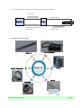
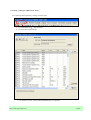
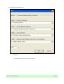
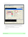
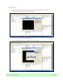
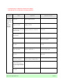
User's Manual
(Linear Series) Rev.1.0
Reference No.
AR08RD001C-EN
Table of Contents
User's manual (machine)
Items
1. Comprehension of Linear Motor
1.1 Driving principle of Linear Motor
A01.01.02
1.2 Composition of Linear Motor
A01.03
1.3 Features of Linear Motor
A01.04
1.4 Sectional drawing of Alpha Linear Motor
A01.04
1.5 Operating direction of Alpha Linear Motor
A01.05
2. Operation of Alpha Linear Motor
2.1 Connection process of Sigma Win Plus Program
A01.06.07
2.2 Setting / Tuning for Alpha Linear Motor
A01.08.09.10
2.3 Manual operation of Linear Motor
A01.10.11
2.4 Early inspection of Linear Motor
A01.12~16
2.5 Troubleshooting of Alarm and warning of Linear Motor
A01.17~26
http://www.alpharobotics.kr
A00.01
1. Explanation of Linear Motor
1.1 Driving principle of Linear Motor
Comparison of internal structure between general Servo Motor and Linear Motor
1.1.1 Internal structure of general Servo Motor
STATOR
PERMANENT MAGNET
SHAFT
ROTOR
1.1.2 Internal structure of Linear Servo Motor
http://www.alpharobotics.kr
A01.01
1.1.3 Comparison of Encoder structure between Servo Motor and Linear Motor
a. Internal structure of Servo Motor
Light source
Rotary disk
Lens
Fixed Slit
Photo detector
Wave shaping
circuit
b. Internal structure of Linear Servo Motor
http://www.alpharobotics.kr
A01.02
1.1.4 Comparison of Encoder structure between Servo Motor and Linear Motor
Pulse train
Winding current
Controller
Driver
Servo motor
Positioning complete signal
Alarm signal
Encoder signal
1.2 Composition of Linear Motor
Coil Assembly
Magnet
Driver
Material
Serial Converter
Scale
Encode
Scale
http://www.alpharobotics.kr
A01.03
1.3 Features of Linear Motor
High precision &
repeatability
By using of linear scale as Encoder system for positioning
feedback, there is almost no mechanism error.
Simplicity / High
torque
As mechanism consists of coil as mover and permanent
magnet as stator, high torque occurs without mechanical
interference.
High speed / high
acceleration
High speedy and accelerated operations are possible due to
no contact movement between mover and stator.
High efficiency
As no contact movement, there is no wear and tear of motor
which causes inefficiency of motor.
Semi-permanency
There is no mechanical processing tolerance due to
sufficient allowable tolerance between mover and stator.
No vibration
It is suitable for LCD and/or semi-conduct manufacturing
process owing to no vibration.
1.4 Sectional drawing of Alpha Linear motor
Encode Bracket
Main Cover
Coil Assembly
Slide Table
Scale
LM Block
Hall Sensor
LM Rail
Encode
http://www.alpharobotics.kr
Base
Magnetic Way
A01.04
1.5 Operating direction of Alpha Linear motor
http://www.alpharobotics.kr
A01.05
2. Operation of Alpha Linear motor
2.1 Connection process of Sigma Win Plus Program
2.1.1 Screen of starting program
a. When starting program, left
screen occurs.
b. Start searching for Linear motor
by click of search located in right
top corner.
2.1.2 Selecting and checking searched model
a. When clicking the Search on the
previous screen, left screen occurs.
b. Click all check boxes, and then
click search on the bottom.
http://www.alpharobotics.kr
A01.06
2.1.3 Connecting searched model
a. Left screen occurs after success
working of the previous screen.
b. Click the searched Linear
Driver so as to turn the line blue
color and then click the connect
button on the bottom.
2.1.4 Successful Screen after connection
This is the Screen after
connection. select menu
for operation.
http://www.alpharobotics.kr
A01.07
2.2 Setting / Tuning for Alpha Linear motor
2.2.1 Selecting menu for Setting / Tuning of Linear motor
a. Click Parameters(U)
Edit Parameter .
b. Or click red circle(Icon menu).
a. On the above screen, click and amend Pn(Parameter) as requested.
http://www.alpharobotics.kr
A01.08
2.2.2 Setting of Alpha-Linear motor
a. The above is Edit screen for amendment after clicking each Pn. set up with value as
requested.
b. Refer explanation for each set point of Nibble.
http://www.alpharobotics.kr
A01.09
2.2.3 Setting of Alpha-Linear motor
a.Pn000 : 0000H
1010H Explanation : Use of Linear motor and position
Control Mode, Operation of forward direction selected.
b. Pn080 : 0000H or 0010H Explanation : A phase / B phase of motor
Standard operation – Switch according to status of Linear motor
c. Pn110 : 0010H is auto-tuning mode and 0012H is manual-tuning mode.
Recommend manual -tuning mode.
When using auto-tuning mode, convert manual-tuning mode after
using of 1~5 times of auto-tuning mode.
d. Pn202 / Pn203 : As Parameter of adjusting electric gear ratio,
set up linear motor through following method.
Explanation : Pn202 is a position value(unit : ㎛) X 256(appointed value of servo)
when inputting one pulse. Pn203 is pitch value of linear scale(unit : ㎛)
Input - Alpha use scale of 40㎛, 20㎛ generally.
Input a value reduced by Pn 202 as numerator and Pn203 as denominator.
e. Pn280 : Setting up pitch value of linear scale.
Alpha use scale of 40㎛, 20㎛ generally
f. Pn483 ,Pn484 : Limited thrust value of forward and reverse direction.
When shipping from factory, the value is 30%, but set up about 300% when using.
2.3 Manual operation of Linear motor
2.3.1 Selecting menu for manual operation of linear motor
a. Click Test Run on menu.
b. After clicking Test Run, small menu, JOG, occurs
c. Click JOG menu and then window of warning message for careful using occurs.
Click OK on the window of warning message, then Dialog box for manual operation occurs.
When servo is turn on, message of being unable to use manual operation occurs
Following page indicates screens of warning
http://www.alpharobotics.kr
A01.10
2.3.2 Warning and error message when Servo is turned on
2.3.3 Dialog box for manual operation
a. After completion of Test Run
operation is available.
JOG, Dialog box showed below occurs and manual
b. Click the Edit and adjust speed
of manual operation.
c. Click the Servo on, then the blue
mark swift to servo on, then test run
is available.
12Page
d. Two buttons of left box are
operable. Using the two buttons,
forward and reverse operation are
available.
http://www.alpharobotics.kr
A01.11
2.4 Early inspection of Linear motor
a. Early inspection is explained through the Trace function provided by Yaskawa
b. Click the Trace & Tuning on the menu shown above, then Pop up menu
occurs,
then click the Trace on Pop up menu, then following screen
occurs.
2.4.1 Trace Menu의 선택화면
Click the Set up
button and input
condition of the
Trace so as to be
operable condition of
the Start button, then
start the Trace
http://www.alpharobotics.kr
A01.12
2.4.2 Setting up the Trace Setting
a. Two kinds of Data corresponding to user's purpose are selective and printed out with Graph.
b. Generally, there are two data, Thrust reference and Feedback speed, for early inspection.
Early inspection process is that select the two above data and check the change of the Thrust
reference in proportion to the Feedback speed.
c. Setting up Trace time is available with inputting time in the red circled box.
d. Unit is ms 's unit.
http://www.alpharobotics.kr
A01.13
2.4.3 Starting Trace
a. After completion of the Set up, the Start button circled with red color become operable.
Click the Start, then the Trace starts as assigned time.
b. Follow screen shows successful start of the Trace.
c. Incorrect conditions or edits are revocable by the Cancel button.
http://www.alpharobotics.kr
A01.14
2.4.4 Interpretation of Graph
a. Red line indicates that the Thrust reference(purple line) increases in the section of
acceleration and deceleration(green line).
b. The Thrust reference is uniform in the section of uniform velocity.
c. If there are great changes of the Thrust reference in the certain section,
problems or mechanical inference may be assumed and so urgent treatment
is required.
http://www.alpharobotics.kr
A01.15
2.4.5 Saving Graph
a. Measured graph may be saved by clicking the red circled save icon.
2.4.6 Opening Graph
a. Saved graph will be opened by clicking red circled open icon.
http://www.alpharobotics.kr
A01.16
2.5 Troubleshooting of Alarm and Warning of Linear motor (based on Sigma 3 (SGDS))
Alarm
Display
A.040
Alarm Name
Situation at Alarm
Occurrence
Cause
Corrective Actions
Parameter setting
error (The
parameter setting
was out of the
allowable setting
range)
Occurred when
The Servopack and
the control power Servomotor capacities do not
supply was turned match each other.
ON.
The Servopack EEPROM and
the related circuit are faulty.
Select the proper combination of
Servopack and servomotor
capacities.
A.041
Dividing pulse
output setting
error
Occurred when
the control power
supply was turned
ON.
Set Pn 281 to the correct value.
A.080
Linear scale
pitch setting
error
Occurred when
The setting value of Pn282
the control power (Linear scale pitch setting) is
supply was turned the factory setting.
ON.
Correct the setting value of
Pn282.
A.840
Encoder data
error (Detected
on the serial
converter unit
side)
Occurred when
A malfunction occurred in the
the control power serial converter unit.
supply was turned
ON.
Turn the control power supply
OFF and then ON again. If this
alarm occurs frequently, replace
the serial converter unit.
The PC dividing pulse set for
Pn281 is out of the setting
range and does not satisfy the
setting conditions.
A servopack board fault
occurred.
Occurred during
operation
Replace the servopack.
A malfunction occurred in the Correct the wiring around the
serial converter unit.
serial converter unit by separating
the serial converter unit cable
from the power line, or by
checking the grounding and other
wiring.
A serial converter unit fault
If this alarm occurs frequently,
occurred.
replace the serial converter unit.
A servopack board fault
occurred.
http://www.alpharobotics.kr
Replace the Servopack.
Replace the servopack.
A01.17
Alarm
Display
A.710
A.720
Alarm Name
Overload :
A.710
: Instantaneous
peak load
Overload :
A.720
: Continuous
peak load
Situation at Alarm
Occurrence
Occurred when the
control power
supply was turned
ON.
Occurred when
the servo was
turned ON.
Cause
Corrective Actions
A servopack board fault
occurred.
Replace the servopack.
The servomotor wiring is
incorrect or the connection is
faulty.
Correct the servomotor wiring.
The encoder wiring is incorrect Correct the encoder wiring.
or the connection is faulty.
A servopack fault occurred.
Occurred when
The servomotor wiring is
the servomotor
incorrect or the connection is
did not run by the faulty.
reference input.
Replace the servopack.
Correct the servomotor wiring.
The encoder wiring is incorrect Correct the encoder wiring.
or the connection is faulty.
The starting force exceeds the
maximum force.
Reconsider the load and operation
conditions, or reconsider the
servomotor capacity.
The polarity detection is not
performed properly.
(When Pn080.0=1 is set)
Correct the settings for the
polarity detection related
parameter.
A servopack fault occurred.
Replace the servopack.
Occurred during The actual force exceeds the
Reconsider the load and operation
normal operation. rated force or the starting force conditions, or reconsider the
largely exceeds the rated force. servomotor capacity.
A servopack fault occurred.
http://www.alpharobotics.kr
Replace the servopack.
A01.18
Alarm
Display
A.300
Alarm Name
Regeneration
error detected
(Detected when
the power to the
main circuit was
turned ON.)
Situation at Alarm
occurrence
Cause
Corrective Actions
Occurred when
A servopack board fault
the control power occurred.
supply was turned
ON.
Replace the servopack.
Occurred when
the main circuit
power supply
turned ON.
Connect an external regenerative
resistor, or set Pn600 to "0" if an
external regenerative resistor is
not connected.
Pn 600 is set to value other
than "0" for a servomotor of
400W or less, and an external
regenerative resistor is not
connected.
Check for incorrect wiring or a Correct the wiring for the external
disconnected wire in
regenerative resistor.
regenerative resistor.
A servopack fault occurred,
Replace the servopack.
such as regenerative transistor
or a voltage sensor fault.
Occurred during Check for incorrect wiring and Correct the wiring for the external
normal operation. disconnection of the
regenerative resistor.
regenerative resistor.
The jumper between B2 and
Correct the wiring.
B3 is removed for a
servomotor of 500W or more.
The regenerative resistor is
disconnected, so the
regenerative energy became
excessive.
Replace the regenerative resistor
or replace the servopack.
Reconsider the load and operation
conditions.
A servopack fault, such as
Replace the servopack.
regenerative transistor and
voltage sensor fault, occurred.
http://www.alpharobotics.kr
A01.19
Alarm
Display
A.320
Alarm Name
Regenerative
Overload
(Detected when
the power to the
main circuit is
turned ON.)
Situation at Alarm
Occurrence
Cause
Corrective Actions
Occurred when the A servopack board fault
control power
occurred.
supply was turned
ON.
Replace the servopack.
Occurred when the The power supply voltage is
main circuit power 270V or more.
supply was turned
ON.
Correct the input voltage.
Occurred during
normal operation
(large increase of
regenerative
resistor
temperature)
Select a proper regenerative
resistance capacity, or reconsider
the load and operation conditions.
The regenerative energy is
excessive.
The regenerating state
continued.
Occurred during
normal operation
(small increase of
regenerative
resistor
temperature)
Occurred at
servomotor
deceleration.
http://www.alpharobotics.kr
The setting of parameter Pn
Correct the set value of parameter
600 is smaller than the
Pn600.
external regenerative resistor's
capacity.
A servopack fault occurred.
Replace the servopack.
The regenerative energy is
excessive.
Select a proper regenerative
resistance capacity, or reconsider
the load and operation conditions.
A01.20
Alarm
Display
A.400
Alarm Name
Overvoltage
(Detected when
the servopack's
main circuit DC
voltage is 410V
or more)
(Detected when
the power to the
main circuit is
turned ON.
Situation at Alarm
occurrence
Cause
Corrective Actions
Occurred when
A servopack board fault
the control power occurred.
supply turned ON.
Replace the servopack.
Occurred when
The AC power voltage is
the main circuit
290V or more.
power supply was
turned ON.
The AC power voltage must be
within the specified range.
A servopack fault occurred.
Replace the servopack..
Occurred during Check the AC power voltage The AC power voltage must be
normal operation. (check if there is no excessive within the specified range.
voltage change.)
Occurred at
servomotor
deceleration.
http://www.alpharobotics.kr
The motor speed is high and
load mass is excessive,
resulting in insufficient
regenerative capacity.
Check the load mass and minus
load specification. Reconsider the
load and operation conditions.
A servopack fault occurred.
Replace the servopack.
The motor speed is high, and
the load mass is excessive.
Reconsider the load and operation
conditions.
A01.21
Alarm
Display
A.820
A.840
Alarm Name
Encoder
checksum error
(Detected on the
serial converter
unit side)
Encoder data
error
(Detected on the
serial converter
unit side)
Situation at Alarm
occurrence
Occurred when
the control power
supply was turned
ON.
Cause
A fault occurred in the serial
converter unit and was
detected by serial converter
unit self-diagnosis.
Set up the serial converter unit. If
this alarm occurs frequently,
replace the serial converter unit.
A servopack fault occurred.
Replace the servopack.
Occurred when
A malfunction occurred in the
the control power serial converter unit.
supply was turned
ON.
A servopack board fault
occurred.
Occurred during
operation.
http://www.alpharobotics.kr
Corrective Actions
Turn the control power supply
OFF and then ON again. If this
alarm occurs frequently, replace
the serial converter unit.
Replace the servopack.
A malfunction occurred in the Correct the wiring around the
serial converter unit.
serial converter unit by separating
the serial converter unit cable
from the power line, or by
checking the grounding and other
wiring.
A serial converter unit fault
occurred.
If this alarm occurs frequently,
replace the serial converter unit.
A servopack board fault
occurred.
Replace the servopack.
A01.22
Alarm
Display
A.C10
Alarm Name
Servo overrun
detected
Situation at Alarm
occurrence
Cause
Occurred when the A servopack board fault
control power
occurred.
supply was turned
ON.
Corrective Actions
Replace the servopack.
Occurred when the The order of phase-U, -V, and Correct the servomotor wiring.
servo was on or a -W in the servomotor wiring is
reference was
incorrect.
input.
A.C20
Phase detection
error
http://www.alpharobotics.kr
Occurred while
motor was
running.
The polarity detection is not
performed properly (When
Pn080.0=1 is set)
Correct the setting for the polarity
detection related parameter.
A serial converter unit fault
occurred.
Replace the serial converter unit.
A servopack fault occurred.
Replace the servopack.
The linear scale signal level is Mount the scale head exactly, or
too low.
replace the linear scale.
The linear scale count-up
direction does not agree with
the forward direction of linear
motor moving coil.
Change the setting of
Pn080.1(motor phase order
selection). Install correctly linear
scale and linear motor moving
coil.
Noise interferes with the hall
sensor signal.
Correct the FG wiring and take
measure to avoid noise.
A01.23
Alarm
Display
A.C90
Alarm Name
Encoder
communication
error
Situation at Alarm
occurrence
Cause
Occurred when the The serial converter unit
wiring and the contact are
control power
supply was turned incorrect.
ON or during
operation.
Noise interference occurred
due to incorrect serial
converter unit cable
specifications.
Corrective Actions
Correct the serial converter unit
wiring.
Use tinned annealed copper
twisted-pair or twisted-pair
shielded wire with a core of at
least 0.12㎟.
Noise interference occurred
The wiring distance must be 20m
because the wiring distance for max.
serial converter unit cable is
too long.
A.C91
A.C92
Encoder
communication
position data
error
Occurred when the
control power
supply was turned
ON or during
operation.
The noise interference
occurred on the signal line
because the serial converter
unit cable is bent or the sheath
is damaged.
The serial converter unit cable
is bundled with a high-current
line or near a high-current line.
Correct the serial converter unit
cable layout.
The FG potential varies
because the influence from
machines on the servomotor
side such as the welder.
Make the grounding for the
machine separately from PG side
FG.
Encoder
Occurred when the Noise interference occurred on
communications control power
the signal line from the serial
timer error
supply was turned converter unit.
ON or during
operation.
Excessive vibration and
shocks were applied to the
serial converter unit.
http://www.alpharobotics.kr
Correct the serial converter unit
cable layout so that no surge is
applied.
Take measure against noise for the
serial converter unit wiring.
Reduce the machine vibration or
mount the servomotor securely.
A serial converter unit fault
occurred.
Replace the serial converter unit.
A servopack board fault
occurred.
Replace the servopack.
A01.24
* Troubleshooting for malfunction without Alarm Display.
(Turn OFF the servo system before executing operations.)
Symptom
Linear
servomotor
does not start
when using
JOG
operation
and host
reference.
Cause
Inspection
Corrective Actions
The control power supply
is not ON.
Check voltage between control
power supply terminals.
Correct the control power circuit.
The main circuit power
supply is not ON.
Check voltage between power
supply terminals.
Correct the power circuit.
Wrong wiring or
Check if the connector CN1 is
disconnection of I/O signal properly inserted or connected.
connector CN1
Correct the connector CN1
connection.
Linear servomotor or serial Check the wiring.
converter unit wiring
disconnected.
Connect the wiring.
Overloaded
Run under no load.
Reduce load or replace with larger
capacity servomotor.
Speed/position reference
not input
Check reference input pin.
Input speed/position reference
correctly.
Servo-ON(/S-ON) input
signal stays OFF.
Check settings of parameters
Pn50A.0 and Pn50A.1.
Correct the parameter setting and turn
ON /S-ON input signal.
Control method selection is Check parameter Pn000.0.
incorrect.
Set parameter to match the
application.
Reference pulse mode
selection is incorrect.
Check the parameter setting for the Correct setting of parameter Pn.200.0.
reference pulse mode(Pn.200.0).
The forward run
prohibited(P-OT) or
reverse run prohibited(NOT) input signal is turned
OFF.
Check P-OT, N-OT input signal.
Turn P-OT or N-OT input signal ON.
A servopack fault
occurred.
A servopack board fault occurred.
Replace the servopack.
http://www.alpharobotics.kr
A01.25
Symptom
Linear servomotor
moves instantly,
and then stops.
Linear servomotor
speed unstable
Cause
Inspection
Corrective Actions
Servomotor wiring is Check the servomotor wiring.
incorrect.
Correct the servomotor wiring.
Serial converter unit
wiring is incorrect.
Correct the serial converter unit
wiring.
Check the serial converter unit
wiring.
Linear scale wiring is Check the linear scale wiring.
incorrect.
Correct the linear scale wiring.
Linear scale
pitch(Pn282) is
incorrect.
Correct the setting of Pn282.
Check the setting of Pn282.
Linear scale counting Check the direction.
up direction and
linear servomotor
moving coil forward
direction are not
agreed.
Change the setting of Pn080.1(motor
phase order selection).
Match the linear scale direction and
moving coil direction.
Wiring connection to Check connection of power
servomotor is
lead(phases U, V, and W) and
defective.
encoder connectors.
Tighten any loose terminals or
connectors.
http://www.alpharobotics.kr
A01.26