1
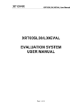
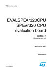
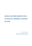
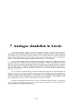
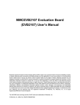
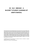
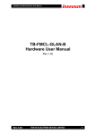
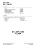
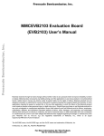
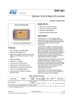
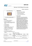
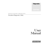
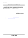
xr
XRD9818EVAL
EVALUATION SYSTEM USER MANUAL
REV. 1.0.0
XRD9818EVAL
Evaluation System
User Manual
1
xr
XRD9818EVAL
EVALUATION SYSTEM USER MANUAL
REV. 1.0.0
1.0 FEATURES
• XRD9818 28-pin TSSOP
• FPGA - Xilinx Spartan II XC2S50
• In-System PROM XC18V01
• Graphical User Interface (GUI) with 25-pin Din Connector for a Standard Parallel Port Interface
• Single Oscillator for Complete Timing Generation and Control
• Analog Switch (EL4331) for Emulating CCD Signals
• Clamping Amplifier (AD8036) for Reset Pulse Emulation
• Line Clamp Control for 40,000 Pixels
• De-Multiplexed Output Provided on a 17-pin Header including a Digital Output Clock
2.0 GENERAL DESCRIPTION
The XRD9818EVAL board is designed to be a test platform that provides a means to evaluate the performance
and functionality of the XRD9818ACG. The eval board contains a Xilinx FPGA that provides all timing signals
required for the proper operation of the XRD9818ACG. The timing and functionality of the FPGA will adjust
and conform to the mode of operation of the XRD9818ACG. A Graphical User Interface (GUI) allows the
evaluation platform to be configured to setup and test the XRD9818ACG in any of its possible modes of
operation. The evaluation system contains emulation circuitry that provides a pseudo CCD signal including a
reset pulse if desired.
XILINX
SPARTAN II
XC2S50
EXAR
XRD9818ACG
CCD
Emulator
EL4331
&
AD8036
GUI
Interface
SRST
SCS
SCK
SDI
ADCLK
BSAMP
VSAMP
LCLMP
RED+
GRN+
BLU+
SDO
XR_LOAD
XR_SCLK
XR_SDI DOUT[16:0]
CNM8
ADCO[7:0]
EMCLK
RPCLK
16
DCLK
MCLK
Ocillator
Master Clock
FIGURE 1. SIMPLIFIED BLOCK DIAGRAM OF XRD9818EVAL
2
H
e
a
d
e
r
xr
XRD9818EVAL
EVALUATION SYSTEM USER MANUAL
REV. 1.0.0
3.0 XRD9818EVAL APPLICATION PLATFORM
The XRD9818EVAL is an evaluation PCB layout designed to test functionality and performance of the
XRD9818. The evaluation platform is controlled via a GUI interface on a PC and requires only power supplies,
inputs to the CCD emulator and test equipment (Logic Analyzer, Oscilloscope) in order to evaluate most of the
functional and performance aspects of the XRD9818. The following sections describe the functional blocks
that make up the XRD9818EVAL system.
3.1
Graphical User Interface (GUI)
The GUI provides all serial port configurations for the XRD9818 plus options for controlling the XRD9818EVAL
setup. To use the XRD9818 GUI simply run XRD9818.exe file and initiate "Start Test" located in the "TEST"
pull down menu.
FIGURE 2. OPEN XRD98181 GUI
The GUI is broken into 7 sections that relate to various register functions of the XRD9818 and control features
of the evaluation system: Color Options, Mode Options, Delay Registers, Polarity Options, Control Options,
CPLD Options and Register Dump. Any changes become activated when the "Update" button is hit.
FIGURE 3. XRD9818 (GUI) GRAPHICAL USER INTERFACE
3
xr
XRD9818EVAL
EVALUATION SYSTEM USER MANUAL
REV. 1.0.0
Configurations can be saved and reloaded via the "File" pull down control located in the upper left hand corner
of the GUI display
FIGURE 4.
3.1.1
Color Options
The XRD9818’s Gain and Offset controls for the individual channels: Red, Green and Blue (registers 0 thru 5),
are controlled here. To modify the gain or offset values simply click on the bit you want to change. It will toggle
between a "1" and a "0". The register value, in HEX, is shown just to the right. To zero out the register
contents (reset to default value) simply set the "0" bit just to the right of the register value.
For the definition of the gain and offset registers see the XRD9818 data sheet.
3.1.2
Mode Options
This section sets the variables defined in the XRD9818’s MODE 1 register. Channel selection, clamp level,
output data format, gain range select, imager mode and line clamp operation are defined by the pull down tabs.
Not only is the XRD9818’s internal MODE 1 register is programmed but the FPGA will automatically adjust the
system timing where needed to evaluate the device in the desired configuration.
For the definition of the MODE 1 register see the XRD9818 data sheet.
3.1.3
Delay Registers
They set the internal delays added to the BSAMP, VSAMP, ADCLK and ADCO (data output delay). Delays can
be added to the sampling clocks (BSAMP, VSAMP & ADCLK) and data valid to help maximize performance of
the XRD9818 and it’s flexibility to externally applied timing.
For the definition of the delay registers see the XRD9818 data sheet.
3.1.4
Polarity Options & Control Options
This section sets the variables defined in the XRD9818’s MODE 2 register. The polarity of the input timing to
the XRD9818 can be individually set to be either active high (default) or active low. Power down and output
enable are set via the Control Options interface.
3.1.5
Register Dump
The internal register configuration of the XRD9818 can be read back via the register dump. When the
"ReadBack" button is hit the register configuration is read and displayed, in hex. The registers are listed from
top to bottom by address.
A description of the readback operation is described in the XRD9818 data sheet.
3.1.6
CPLD options
The channel output sample clock is defined by the Color Grab. The Xilinx FPGA provides a data valid clock to
the data header (S5) to be used to sample the output data. For example, if the XRD9818 is being operated in
3-CH mode all three channel’s output data is sampled when the "Color Grab" is set to All Channels. Individual
channel outputs can be sampled while in 3-CH operation by selecting the appropriate option. If "Red Channel"
is selected, the CPLD supplies a sample clock only when the red channel data is available at S5.
The "Reset CPLD" button is for use upon initialization of the evaluation platform or if a system reset is needed.
4
xr
XRD9818EVAL
EVALUATION SYSTEM USER MANUAL
REV. 1.0.0
3.2
Spartan II FPGA (XC2S50)
At the heart of the evaluation platform is the Spartan II. The FPGA provides the timing, control and pattern
generation for the complete evaluation of the XRD9836. It reads the control information from the GUI and
performs the appropriate write/read operation with the XRD9818. In addition to configuring the XRD9818 it
will provide the appropriate timing signals to the evaluation system required to operate the XRD9818 in that
mode. For example, if the XRD9818 is configured for 3-CH, CCD mode and nibble output operation the FPGA
will provide the correct timing adjustments to the ADCLK, BSAMP, VSAMP, emulator clks, and 16bit out latch
with sample clock so that the user does not need to adjust any of their equipment.
3.3
In-System PROM (XC18V01)
The FPGA can be programmed in two ways. A standard JTAG header is provided to allow programming each
time the XRD9818EVAL is powered up. Or, an in-system PROM is provided to automatically program the
FPGA upon power up. The JTAG header allows flexibility to provide verilog source codes for customer
verification.
3.4
25-DIN Parallel Connector for PC Interface
The 25-DIN connector establishes the connection for the GUI control over the XRD9818EVAL through the
parallel port of a PC. The GUI provides all serial port configurations XRD9818 plus options for controlling the
XRD9818EVAL. When selecting options through the GUI, the program bursts the FPGA input with the pattern
shown below in Figure 5. Please note that the pattern is not the same as the serial write pattern to the serial
timing port of the XRD9818. The extra SCLK’s after SCS goes back high are required for a readback
operation from the 9818’s internal registers. If the evaluation platforms is performing a readback operation the
first clock after SCS goes high is required to latch the parallel data output from the 9818 and the next 10 clocks
shift out the register content data, msb first.
XRD9818 GUI Write/Read Timing
LOAD
SCLK
SDI
dc
A3 A2 A1 A0
dc
D9 D8 D7 D6 D5 D4 D3 D2 D1 D0
SDO
D9 D8 D7 D6 D5 D4 D3 D2 D1 D0
D
U
M
M
Y
Address
D
U
M
M
Y
Write Data
Read Data
FIGURE 5. XRD9818EVAL GUI INTERFACE TIMING
5
xr
XRD9818EVAL
EVALUATION SYSTEM USER MANUAL
REV. 1.0.0
3.5
CCD Emulator Circuitry
The emulation circuitry is intended to provide a pseudo CCD signal in order to evaluate the XRD9818 when
configured for CCD operation. This is accomplished by the use of an analog switch (EL4331C) as seen in the
evaluation board schematic . The basic function of the EL4331C (U5) is to switch each channels output
between the its two inputs signals according to the polarity of the EMCLK timing signal. The inputs for each
channel will be used to emulate the black reference level and video level of a CCD signal. If you look at the
Figure 6 below you will see that the EMCLK connects the Black_Level (INxA - pins 3, 6, 12 of U5) input to the
output when high and the Video input (INxB - pins 4, 5, 11 of U5) when the EMCLK is low. The resulting
output signal as shown in the example timing for a Black Level=5V and a Video=4V is a signal toggling
between 5V and 4V with the EMCLK.
EMCLK
BLACK_LEVEL
5V
xxx(+)_VIDEO
4V
OUTx
5V
4V
FIGURE 6. BASIC FUNCTION OF ANALOG SWITCH
To be able to test the XRD9818 for DNL & INL type specifications a sine wave generator can be connected to
the Video input that has its peaks at 5V and 2V. This will cause the output of the XRD9818 to generate a
digital sinewave that goes from zero code to full scale under the following conditions:CCD mode, GS=0,
gain=1x, and offset reg adjusted to correct for any system offsets.
A reset pulse can be added to the emulated CCD signal by the use of the clamping amplifier (U8). It operates
on the same principle as the EL4331 but has a faster settling time. The reset pulse can be adjusted by the
input levels to the device. The clocking is done by the RSCLK provided from the FPGA. An example of an
emulated CCD signal with reset pulse is shown below in Figure 7.
FIGURE 7. EXAMPLE OF CCD EMULTOR OUTPUT WITH RESET PULSE
6
xr
XRD9818EVAL
EVALUATION SYSTEM USER MANUAL
REV. 1.0.0
3.6
Digital Output Interface
The interface to a Logic Analyzer is a 17x2 header (S5). It provides 16 bits of data, latch clock and individual
ground for each signal. The rising edge of the latch clock is intended to identify when data is valid.
4.0 EVALUATION BOARD - POWER, JUMPER AND HEADER INFORMATION
TABLE 1:
IDENTIFIER
NAME
DESCRIPTION
B1
3V
Eval Board Power (3.3V typically)
B2
GND
Eval Board Ground
B3
5V_VCC
Positive Power Supply for Pixel Emulator
B4
-5V_VEE
Negative Power Supply for Pixel Emulator
J1 - J7
External Timing Jumpers
Used when external timing is applied and FPGA is not used to
supply system timing.
J8, J9 & J10
Emulator Input Jumpers
Series jumpers to connect/isolate XRD9818 analog inputs.
J11
Emulator Reset Pulse Jumper Used to create Reset pulse as part of emulated CCD pixel input
J12 & J13
XRD9818 Power Jumpers
Used to Isolate the XRD9818 from Eval Board for IDD
measurements.
S1
Analog Input Header
Used to ground XRD9818 analog inputs
S2
Reference Header
Test points for CAPP, CAPN, & CMREF
S3
GPIO Header
General purpose pins that can be used for debug of FPGA
S4
JTAG Header
JTAG header used to program PROM & FPGA
S5
Data Output Header
Logic analyzer header for reconstructed 16bit digital outputs
P1
Parallel Port Interface
25-pin Din Connector standard parallel port interface for GUI
control
5.0 REWORK INFORMATION
Jumper near U3 (PROM) to supply power (VDD3V) to pins 18, 19 & 20.
7
XRD9818EVAL
EVALUATION SYSTEM USER MANUAL
xr
REV. 1.0.0
6.0 XRD9818EVAL SCHEMATICS
FIGURE 8. XRD9818 & SPARTAN II
J1
6
5
4
J2
J3
R4
J4
SMB5
LOAD
R5
J5
R6
J6
R7
2
50
AGND
JTAG
S4
SMB2
BSAMP
1
2
3
R10
1
14
2
15
3
16
4
17
5
18
6
19
7
20
8
21
9
22
10
23
11
24
12
25
13
SMB3
VSAMP
P1
AGND
AGND
50
AGND
SMB4
LCLMP
C5
0.1uf
DVDD
50
AGND
AGND
OPEN
CONNECTOR DB25_0
AGND
5
6
4
17
18
20
19
VCC
VCC
VCCO
U3
R21
470
470
D0/DATA
CLK
OE/RST
CE
CEO
XC18V01
36
SMB
R17
470
R15
470
SMB8
GND
R16
R14
11
TMS
TCK
TDI
TDO
50
R18
D7
D6
D5
D4/CF
D3
D2
D1
R19
SMB6
SDI
R8
300
AGND
AGND
R11 short
R12 short
R13 short
1
3
8
10
13
12
9
14
7
15
2
16
AGND
50
4.7K
36
AGND
50
GND
VCC
SMB7
SCLK
CLK
U4
AGND
R9
5
4.7K
R20
VDD3v
4
8
91
79
77
76
75
74
109
111
106
39
37
68
72
69
38
142
2
32
34
88
18
15
+
J7
VDD3v
LCLMP
VSAMP
BSAMP
ADCCLK
GPIO_9
GPIO_8
GPIO_7
GPIO_6
GPIO_5
GPIO_4
GPIO_3
GPIO_2
GPIO_1
GPIO_0
ADCO0
ADCO1
ADCO2
ADCO3
ADCO4
ADCO5
ADCO6
ADCO7
XR_LOAD
XR_SDI
XR_SCLK
AGND
DOCLK
DOUT15
DOUT14
DOUT13
DOUT12
DOUT11
DOUT10
DOUT9
DOUT8
DOUT7
DOUT6
DOUT5
DOUT4
DOUT3
DOUT2
DOUT1
DOUT0
EMCLK
RESETCLK
Spartan II FPGA XC2S50
AGND
VDD3v
MCLK
SDO
SRST
SDI
SCS
SCK
M0
M1
M2
DIN
CCLK
INIT
DONE
PGM
DOUT
TMS
TCK
TDI
TDO
GCLK0
GCLK2
GCLK3
U2
VDD2v5
AGND
1
+
open
50
2
+
1
+
2
+
1
+
2
+
1
+
2
1
+
Oscillator_0
26
23
22
21
20
19
13
12
11
10
7
6
5
4
3
122
123
124
129
130
131
132
133
136
137
139
141
65
63
62
60
59
58
57
56
50
49
48
47
46
44
43
41
40
LCLMP
VSAMP
BSAMP
ADCLK
LOAD
SDI
SCLK
S3
1
2
3
4
5
6
7
8
9
10
GPIO HEADER
1
2
3
4
5
6
7
8
9
10
11
12
13
14
15
16
17
1
S5
t
TP4
34
33
32
31
30
29
28
27
26
25
24
23
22
21
20
19
18
HEADER 17X2
g
VDDA3v
AGND
VDDA3v
2
AGND
AGND
1
2
3
4
5
6
7
8
9
10
11
12
13
14
BLU+
GRN+
AGND
CMN-
U1
AVDD
CAPP
CMREF
RED+
LCLMP
SDI
DVDD
LOAD
DGND
ADCLK
ADCO[2]
ADCO[3]
ADCO[4]
ADCO[5]
ADCO[6]
ADCO[7]
AVDD
AGND
CAPN
VSAMP
SCLK
BSAMP
ADCO[0]
XRD9818
ADCO[1]
28
27
26
25
24
23
22
21
20
19
18
17
16
15
VDDD3v
AGND
TP2
TP1
1
1
C2
C1
1nf
1nf
1nf
1nf
1
C3
TP3
C4
t
t
t
g
g
g
2
2
2
1
2
3
S2
HEADER 3
RESETCLK
EMCLK
AGND
AGND BAR
AGND
AGND BAR
AGND
Title
C
Size
Date:
Monday, March 24, 2003
XRD9818EVAL
Document Number
XRD9818 & Spartan II
S1
AGND
HEADER 4X2
Sheet
Red Input
Green Input
Blue Input
Common Ref Input
CMREF
CAPP
CAPN
1
of
3
H:\ORCAD\PROJECTS\9818\9818EVAL_3A.DSN
AGND
2
R3
+
2
1
+
AGND
1
A
Rev
8
1
2
3
4
2
1
16
35
36
53
70
71
90
107
108
127
144
VDDo
VDDo
VDDo
VDDo
VDDo
VDDo
VDDo
VDDo
VDDo
VDDo
VDDo
VDDo
VSS
VSS
VSS
VSS
VSS
VSS
VSS
VSS
VSS
VSS
VSS
VSS
VSS
VSS
VSS
VSS
8
7
6
5
1
R2
+
2
+
1
+
9
14
24
55
82
92
97
125
VDDi
VDDi
VDDi
VDDi
VDDi
VDDi
VDDi
VDDi
8
17
25
33
45
52
61
73
81
89
98
110
119
128
135
143
SMB1
ADCLK
VDD3v
R1
VEE5v
AGND
OUT1
OUT2
+
0
EMCLK
U5
EL4331C
OUT3
1
8
9
J UMPER
10uf
+ C19
R33 50
AGND
C23
0.1uf
R25
R27
R42
0
0
0
CMN-
R29
AGND
J9
J8
J10
2
VCC5v
AGND
IN1A
IN1B
IN2A
IN2B
IN3A
IN3B
A/B
PD
J11
AGND
0.1uf
C20
AD8036
6
U8
AGND
R30
VCC5v
+
-
R36 140
C22
10uf
0.1UF
(high => black level, low => video level)
3
4
6
5
12
11
16
14
3
2
R38
0
1
2
BLACK LEVEL
10K
R23
VCC5v
AGND
C18
0.1uf
R32 130
C21
0.1uf
R37
open
1
2
R22
AGND
RED+_VIDEO
R24
AGND
GRN+_VIDEO
R26
AGND
BLU+_VIDEO
R28
AGND
RESETCLK
R34
AGND
open
C8
AGND
2
AGND
1
C6
AGND
SMB13
0.01UF
VEE5v
J UMPER
J UMPER
J UMPER
Red Input
Green Input
Blue Input
Common Ref Input
Monday, March 24, 2003
Sheet
2
of
Pixel Emulator Circuitry with Reset Pulse
Docume nt Numbe r
XRD9818EVAL
3
H:\ORCAD\PROJECTS\9818\9818EVAL_3A.DSN
Title
B
Size
Date:
A
Rev
9
0.1UF
C9
AGND
OPEN
13
VEE
GND
10
OPEN
0.01UF
C7
1
15
VCC
GND
2
SMB9
SMB10
SMB11
SMB12
OPEN
OPEN
OPEN
GND
7
8
5
RESET PULSE LEVEL
R31
AGND
BLACK LEVEL
R35
AGND
OPEN
OPEN
7
4
SMB14
SMB15
xr
XRD9818EVAL
EVALUATION SYSTEM USER MANUAL
REV. 1.0.0
FIGURE 9. CCD EMULATOR
0.1uF
C39
C25
0.1uF
C50
0.1uF
C40
0.01uF
C26
0.1uF
C51
0.1uF
C41
0.01uF
C27
0.1uF
C52
0.1uF
C42
C35
0.1uF
C28
0.1uF
C53
0.1uF
C43
0.1uF
C34
0.1uF
C24
+
+
1
1
+
+
2
2
B2
AGND
0.1uF
POWER AND BYPASS CIRCUITRY
C32
BANNANA PLUGS
AGND
C46
+
+ C31
22uF
VDD2v5
AGND
AGND
B3
C29
MHOLE
M4
MHOLE
M3
MHOLE
M2
MHOLE
M1
+ 10uF
1
1
1
VCC5v
Title
B
Size
B4
C30
Power & Decoupling
Document Number
Wednesday, April 30, 2003
XRD9818EVAL
1
VEE5v
Sheet
3
of
3
H:\ORCAD\PROJECTS\9818\9818EVAL_3A.DSN
EXAR
EXAR
U15
10uF
-5V_VEE
2
470
R40
4
5V_VCC
OUT
+
+
+
OUT
470
U9
LT1174
IN
C44
C54
C56
AGND
1
GND
VDD3v
3
D1
5.6V
GND
1
3V
B1
+
LED
D2
0.1uF
J12
+
+
J13
10uF
AGND
CAPP
CAPN
R41
1
Date:
A
Rev
10
AGND
VDD3v
AGND
VDD2v5
AGND
R39
1
2.2uF
1
2
VDDA3v
0.1uF
C49
AGND
VDDD3v
0.1uF
C38
1
2.2uF
2.2uF
470
CMREF
C45
C55
C57
0.1uF
0.1uF
0.1uF
C48
1
2.2uF
10uF
10uF
0.1uF
0.1uF
+
XRD9818EVAL
EVALUATION SYSTEM USER MANUAL
xr
REV. 1.0.0
FIGURE 10. POWER AND BYPASS CIRCUITRY
C36
0.1uF
C37
C33
C47