1
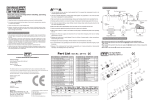
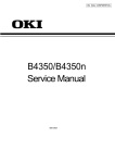
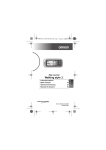
¡
OKIPAGE 4w
LED Page Printer
Maintenance Manual
All specifications are subject to change without notice.
PREFACE
This Maintenance Manual describes the field maintenance methods for LED Page Printers.
This manual is written for use by service persons. Please note that you should refer to the Printer
Handbook for the handling and operating methods of the equipment.
CONTENTS
1. CONFIGURATION ..................................................................................... 1 - 1
1.1 System Configuration ........................................................................ 1 - 1
1.2. Printer Configuration .......................................................................... 1 - 2
1.3 Specification ...................................................................................... 1 - 3
1.4 Safety Standards ............................................................................... 1 - 5
1.4.1
1.4.2
Certification Label .................................................................................... 1 - 5
Warning Label ......................................................................................... 1 - 5
2. OPERATION DESCRIPTION ....................................................................
2.1 Main Control Board ............................................................................
2.2 Power Supply Unit .............................................................................
2.3 High-Voltage Power Supply Board ....................................................
2.4 Electro-Photographic Processor ........................................................
2.5 Electro-Photographic Process ...........................................................
2.5.1
2-1
2-3
2-4
2-4
2-6
2 - 10
Explanation of Each Process Operation .................................................. 2 - 12
2.6 Paper Jam Detection ......................................................................... 2 - 18
2.7 Toner Low Detection.......................................................................... 2 - 20
2.8 Cover Open ....................................................................................... 2 - 21
3. PARTS REPLACEMENT ...........................................................................
3.1 Precautions for Parts Replacement ...................................................
3.2 Parts Layout.......................................................................................
3.3 Replacing Parts .................................................................................
3.3.1
3.3.2
3.3.3
3.3.4
3.3.5
3.3.6
3.3.7
3.3.8
3.3.9
3.3.10
3.3.11
3.3.12
3.3.13
3.3.14
3.3.15
3.3.16
3.3.17
3-1
3-1
3-3
3-6
Extend Plate ............................................................................................ 3 - 6
LED Head and Head Spring .................................................................... 3 - 7
Transfer Roller ......................................................................................... 3 - 8
Upper Cover Assy ................................................................................... 3 - 9
High-Voltage Power Supply Board .......................................................... 3 - 10
Top Cover Assy and Flat Cable Assy ...................................................... 3 - 11
Paper Holder ........................................................................................... 3 - 12
Side Plate M and Idle Gear ..................................................................... 3 - 13
Registration Roller ................................................................................... 3 - 14
Drive Shaft E (Eject) and Eject Roller ..................................................... 3 - 15
Heat Assy ................................................................................................ 3 - 16
Pressure Roller B (Back Up Roller) ......................................................... 3 - 19
Separator Guide ...................................................................................... 3 - 20
Pulse Motor (Main) .................................................................................. 3 - 22
Hopping Shaft Assy ................................................................................. 3 - 23
Paper Sensor E, Paper Sensor Exit and Toner Sensor Assy ................. 3 - 24
Base Plate ............................................................................................... 3 - 25
4. ADJUSTMENT ........................................................................................... 4 - 1
4.1 Adjustment Types and Functions ...................................................... 4 - 1
4.1.1
4.1.2
Printer Driver ........................................................................................... 4 - 1
Engine Maintenance Utility ...................................................................... 4 - 2
4.2 Adjustment When Replacing a Part ................................................... 4 - 2
4.2.1
4.2.2
4.2.3
Setting LED Head Drive Time ................................................................. 4 - 2
Setting the LED Head Dot Count ............................................................ 4 - 3
Uploading and Downloading EEPROM Data .......................................... 4 - 4
5. PERIODICAL MAINTENANCE ................................................................. 5 - 1
5.1 Periodical Replacement Parts ........................................................... 5 - 1
5.2 Cleaning............................................................................................. 5 - 1
5.2.1
Cleaning of LED Lens Array .................................................................... 5 - 1
6. TROUBLESHOOTING PROCEDURES ....................................................
6.1 Troubleshooting Tips .........................................................................
6.2 Check Points Before Correcting Image Problems .............................
6.3 Notes When Correcting Image Problems ..........................................
6.4 Preparation Before Troubleshooting ..................................................
6.5 Troubleshooting .................................................................................
6.5.1
6.5.2
6.5.3
6-1
6-1
6-1
6-1
6-1
6-2
Status Monitor Message List ................................................................... 6 - 2
Status Message Troubleshooting ............................................................ 6 - 6
Image Troubleshooting ............................................................................ 6 - 13
7. WIRING DIAGRAM ................................................................................... 7 - 1
7.1 Interconnect Signal Diagram ............................................................. 7 - 1
7.2 PCB Layout ........................................................................................ 7 - 2
8. PARTS LIST .............................................................................................. 8 - 1
APPENDIX A LOCAL PRINTING ............................................................... A - 1
APPENDIX B PARALLEL INTERFACE ..................................................... B - 1
APPENDIX C MAINTENANCE UTILITY ..................................................... C - 1
1. CONFIGURATION
1.
CONFIGURATION
1.1
System Configuration
The OKIPAGE 4w consists of a control block, a power supply unit, and an engine block. (See
Figure 1-1.)
ENGINE UNIT
Paper Feed Mechanism
Hopper
Plate
Electro-photographic
Processor
High-Voltage Power
Supply Board
Main Control Board
Power Supply Unit
Figure 1-1
1-1
1.2
Printer Configuration
The printer unit consists of the following five hardware components:
•
•
•
•
•
Electro-Photographic Processor
Paper Feeder
Main Control Board
High-Voltage Power Supply Board
Power Supply Unit
Figure 1-2 is the configuration of the printer unit.
Upper Cover Assy
EP Unit
Top Cover Assy
Heat Assy
Power Supply Unit
Main Control Board
High-Voltage Power
Supply Board
Figure 1-2
1-2
1.3
Specification
(1) Type
Desktop
(2) Outside dimensions
(excludes protruding
portion)
Height 5.9”
Width 12.2”
Depth 7.5”
(3) Weight
3.8 kg
(4) Development method
Exposure method
Dry non-magnetic development system
LED stationary head
(5) Paper used
<Type>
• Standard paper
– Xerox 4200 (20 lbs)
• Application paper (manual face-up feed)
– Label
– Envelope
– OHP paper (Transparency)
(150 mm)
(310 mm)
(191 mm)
<Size>
14" (355.6 mm) (Max.) x 8.5" (215.9 mm)
<Thickness>
– Automatic feed:
– Manual feed:
16 to 28 lbs (60 to 90 g/m2)
Label, Envelope, OHP paper (transparency)
(6) Printing speed
First print:
Continuous print:
Warm-up time:
(7) Paper feeding method
Automatic paper feed or manual paper feed
(8) Paper delivery method
Face down
(9) Resolution
300 dpi x 300 dpi, 600 dpi x 600 dpi (quasi)
(10) Power input
230 VAC +15%, -14% (for OEL/INT)
120 VAC +6%, -15% (for ODA)
(11) Power consumption
Peak:
Typical operation:
Idle:
Power save mode:
1-3
25 seconds (A4) (after warm-up)
4 sheets/minute (A4)
40 seconds (120 VAC for ODA, 230
VAC for OEL/INT) (at room temperature 77 ˚F (25 ˚C))
450W
100W
30W
5W
(12) Temperature and humidity
Temperature
Humidity
During operation
10 to 32 ˚C
20 to 80% RH (relative humidity)
In storage
–10 to +43 ˚C
10 to 90% RH (relative humidity)
No condensation is permissible.
Caution: Temperature and humidity in storage are measured with the PN212
being packed; they are valid for one year.
(13) Noise
During operation:
Standby:
(14) Consumables
Toner cartridge kit
1,000 (5% duty)
Image drum cartridge 10,000 (at continuouts printing)
1-4
48 dB (A) or less
38 dB (A) or less
1.4
Safety Standards
1.4.1
Certification Label
The safety certification label is affixed to the following location of the OKIPAGE 4w:
ODA
OEL
/OKI-INT
1.4.2
Warning Label
Warning labels are affixed to the locations that may cause bodily injury.
During maintenance, do work with enough care while following instructions on these warning
labels.
1-5
2.
OPERATION DESCRIPTION
2.
OPERATION DESCRIPTION
The OKIPAGE 4w consists of a main control board, a high-voltage power supply board, a power
supply unit, and an electro-photographic processor. The OKIPAGE 4w receives print data from
a higher-level interface and sequentially stores it in memory. The OKIPAGE 4w decodes and
edits the received data while storing print data from the interface in memory. It sequentially
transfers the edited data to the LED head for each dot line. The electro-photographic processor
then prints the data on sheets of paper.
The display of the higher-level host is used for device operation and status display.
Figure 2-1 is the block diagram of the OKIPAGE 4w.
2-1
2-2
5V
OVL
5V
Reset
circuit
TEMP
TR-VSEN
TR-ISEN
Sensors
Electromagnetic
clutch
Main motor
LED head
Parallel
I/F
EEPROM
10 MHz
MSM65917
(nX-8 core)
Driver
A0 ~ A10
AD0 ~ AD7
A8 ~ A15
HEAT ON
Parallel
I/F
Manual feed sensor
Paper sensor
Outlet sensor
Toner sensor
Cover open switch
Driver
Driver
Switching
power supply
+24 V
+5 V
0VL
0VP
<Power Supply Unit>
AC output ON/OFF
<High-voltage Power Supply Board>
High voltage
power
supply
LED
LS07
CN
Driver
TEMP
High-voltage
power I/F
TR-VSEN
TR-ISEN
Sensors
LED
Electromagnetic
clutch
Main motor
LED head
Parallel
I/F
Figure 2-1 Block Diagram
<Main Control Board>
LED
HEAT ON
OE
CS
High-voltage power I/F
D-RAM
(128 KByte)
D0 ~ D3
Address
latch
A0 ~ A7
EPROM
(52 KByte)
D0 ~ D7
Main motor
AC
(120 V/230 V)
Heater
(Halogen lamp)
EP cartridge
Thermistor
Electromagnetic
clutch
M
LED head
2.1
Main Control Board
The main control board consists of a one-chip CPU, a program ROM, a DRAM, an EEPROM, a
host interface circuit, and a mechanism driving circuit. The mechanism driving circuit consists of
a LED head, a main motor, and an electromagnetic clutch.
(1) One-chip CPU
The one-chip CPU is a custom CPU (8-bit internal bus, 8-bit external bus, 10-MHz clock)
incorporating mask ROM and CPU peripheral devices. This CPU has the functions listed in
the table below.
Built-in Device
Function
DRAM controller
Controls DRAM.
DMA controller
Transfers image data from Parallel I/F to DRAM, from DRAM to a video output port and
between CPU and DRAM.
Parallel interface controller
Controls the parallel interface.
Video output port
LED STB output port
Controls LED head.
Timer
Generates various control timings for monitoring paper feeding and a paper size.
I/O port
Inputs and outputs the sensor signals and motor signals, etc.
Also performs I/O for EEPROM.
A/D converter
Inputs the feedback signals from a high-voltage generation circuit and thermistor signal.
(2) Program ROM
Program ROM contains a program for the equipment. EPROM is used as program ROM.
When mask ROM in the one-chip CPU explained in (1) above is valid, the EPROM is not
mounted. (For details on short wiring setting, see Section 7.2.)
(3) DRAM
DRAM is used as resident memory.
(4) EEPROM
EEPROM holds the following data:
• Menu data
• Counter value
• Adjustment value
(5) Parallel interface
The parallel interface receives parallel data from the host; it conforms to the IEEE1284
specification.
2-3
2.2
Power Supply Unit
The power supply unit supplies +5 V and +24 V to the main control board according to 230 VAC
/120 VAC.
Output voltage
Application
+5 V
Used to generate a logic circuit and a high voltage.
+24 V
Used to drive the motor and electromagnetic clutch.
The power supply unit also contains a heater drive circuit.
2.3
High-Voltage Power Supply Board
(1) High-Voltage power supply circuit
The high-voltage power supply circuit generates the following voltages required for the
electro-photographic processor from +5 V according to the control sequence from the main
control board. When the cover is open, +5 V supply is automatically interrupted to stop highvoltage output.
Output
Voltage
Application
CH
–1.35 KV
Voltage to be applied to a charge roller.
DB
–300 V/+300 V
Voltage to be applied to a developing roller.
SB
–450 V/ 0 V
Voltage to be applied to a sponge roller.
CB
+400 V
Voltage to be applied to a cleaning roller.
TR
+500 V ~ +3.5 KV/–750 V
Voltage to be applied to a transfer roller.
Caution: The TR voltage varies with medium and transfer roller impedance.
2-4
(2) Sensors
The high-voltage power supply board consists of the high-voltage power supply circuit that
supplies power to the electro-photographic processor system and the photosensor that
detects a paper feeding system and toners.
Figure 2-2 shows the sensor layout drawing.
Exit roller
Outlet sensor
Heat roller
Transfer roller
Feed roller
Paper feeding direction
Paper sensor
Toner
sensor
assy
Hopping
roller
Manual feed sensor
Figure 2-2
Sensor
Function
Sensing State
Manual feed
sensor
Monitors whether paper was inserted into the manual feed sensor
section.
ON: Paper exists.
OFF: No paper exists.
Paper sensor
Detects the leading part of the paper.
Monitors paper feeding.
ON: Paper exists.
OFF: No paper exists.
Outlet sensor
Monitors paper feeding and the paper size according to the paper
sensor arrival and passing time.
ON: Paper exists.
OFF: No paper exists.
Toner sensor
Detects the low toner status.
ON (long): Toner low
OFF (short): Toner High
2-5
2.4
Electro-Photographic Processor
The electro-photographic processor prints out the image data to be sent from the main control
board on sheets of paper. Figure 2-3 shows the layout drawing of the electro-photographic
processor.
(1) Image drum unit
The image drum unit makes a toner adhere to the formed electrostatic latent image with static
electricity. This electrostatic latent image is formed by the lights irradiated from LED heads.
(2) Electromagnetic clutch
The electromagnetic clutch controls the rotation of the hopping roller according to signals
from the control block.
2-6
2-7
Manual feed sensor
Manual
printing
Feed roller
ON OFF
10
Paper sensor
Developing roller
(ø 14.000)
Drum roller
(ø 16.000)
23.18
10
17.23
Figure 2-3
Tray printing
LED head
OFF
32.00
6.85
Cleaning roller
(ø 9.000)
26.50
Transfer roller
(ø 15.000)
64.60
Hopping roller
20.32
Outlet sensor
Layout Drawing of Electro-Photographic Processor
12.72
6.77
Charge roller
(ø 9.000)
Heat roller
(ø 19.910)
Exit roller
ON
10
Single tray
OFF
(3) Pulse motor (Main)
This pulse motor of 48 steps/rotation is two-phase excited by the signal from the main control
board; it performs feeding control by switching normal rotation to reverse rotation or vice
versa and turning on/off the electromagnetic clutch. The relationship between the main
motor, electromagnetic clutch, regist gear, drum gear, hopping roller is shown in the table
below and on the subsequent pages.
Main Motor
Electromagnetic Clutch
Hopping Roller
Regist Gear
Drum Gear
Operation
Normal rotation
OFF
Non-rotation
Non-rotation
Rotation
Warm-up
ON
Rotation
Rotation
Rotation
Hopping
OFF
Non-rotation
Rotation
Rotation
Prinitng
Reverse rotation
(4) LED head
The shift and latch registers receive image data from the main control board for each dot line.
2,560 or 2,496 LEDs are driven to radiate the image drum.
(5) Heat Assy
The heat Assy consists of a heater, a heat roller, a thermistor, and a thermostat.
The power supply unit supplies AC voltage to the heater according to the HEATON signal
from the main control board to heat the heat roller. The main control board monitors the heat
roller temperature via the thermistor and keeps the temperature constant by turning on/off
the heater AC voltage supply.
If the heat roller temperature rises abnormally, the thermostat of the heater voltage supply
circuit functions to forcibly suspend the AC voltage supply.
2-8
2-9
Manual
feed
sensor
Manual printing
Transfer roller
Cleaning roller
CH roller
Heat roller
Outlet
sensor
Exit roller
2
Figure 2-4 Schematic Drawing of OKIPAGE 4w Paper Feeding
Reverse rotation of pulse motor (main):Drum roller, transfer roller, cleaning roller, CH roller, developing roller, heat roller, exit roller, feed roller,
hopping roller rotation
Hopping operation from the tray, however, is performed when the electromagnetic clutch is turned on.
Roller control by pulse motor (main)
1 Normal rotation of pulse motor (main):Drum roller, transfer roller, cleaning roller, CH roller, developing roller, heat roller, exit roller rotation
TRAY printing
Drum roller
1 Motor to be driven by normal
rotation of pulse motor (main)
Developing roller
Hopping roller
Paper sensor
Feed roller
2 Roller to be driven by reverse
rotation of pulse motor (Main)
2.5
Electro-Photographic Process
(1) Electro-photographic process
The electro-photographic process is outlined below.
1 Charging
The surface of the OPC drum is charged negatively and uniformly by applying the DC
voltage to the CH roller.
2 Exposure
Light emitted from the LED head irradiates the negatively charged surface of the OPC
drum. The surface potential of the irradiated surface attenuates to form the electrostatic
latent image corresponding to the image signal.
3 Development and residual toner recovery
The negatively charged toner is brought into contact with the OPC drum, adhering to the
electrostatic latent image on the OPC drum by static electricity. This adhesion causes
the electrostatic latent image to change to a visible image.
At the same time, the residual toner on the OPC drum is attracted to the developing
rollerby static electricity.
4 Transfer
When paper is placed over the image drum surface, the positive charge which is
opposite in polarity to that of the toner, is applied to the reverse side by the transfer roller.
The toner is attracted by the positive charge and is transferred onto the paper. This
results in the transfer of the toner image formed on the image drum onto the paper.
5 Cleaning
The cleaning roller temporarily attracts the residual toner on the transferred OPC drum
with static electricity, then returns the toner to the OPC drum.
6 Fusing
The transferred unfused toner image is fused to a sheet of paper by applying heat and
pressure to the image.
Figure 2-5 is a flow for the electro-photographic process.
2 - 10
2 - 11
Paper ejection
Fusing
Fusing
Paper feeding
Heat roller
Outlet sensor
Paper eject
roller
Paper delivery
Back-up
roller
Figure 2-5
Cleaning
Cleaning
roller
Power
supply
Charge
roller
Power
supply
Transfer
Transfer roller
Transfer
Development
Paper sensor
Development
Developing
roller
Power
supply
Paper feed
Feed roller
Flow for Electro-Photographic Process
Power
supply
Cleaning
Charging
Exposure
LED head
Control signal
Paper hopping
Manual feed
sensor
Manual feed
section
Paper
holder
: Paper feeding path
: OPC drum rotation direction
Hopping
roller
Paper
supply
Toner
cartridge
2.5.1
Explanation of Each Process Operation
(1) Hopping
As shown in the figure below, the clutch for hopping is turned on/off according to current ON/
OFF to a coil.
When the clutch is OFF
Spring for resetting
Hopping gear
Clutch plate
Coil
Magnetic
substance plate
Pin
Hopping shaft
Hopping roller
Engagement section
When the clutch is ON
Hopping gear
Clutch plate
When the clutch is on, the hopping gear engages with the clutch plate to rotate the hopping
roller.
When the clutch is off, the hopping gear is separated from the clutch plate by the spring for
resetting, disabling the rotation of the hopping roller.
2 - 12
(2) Printing and warm-up
At warm-up
Triple gear
Transfer gear
Resist gear
Idle gear
Planetary gear
a"
a'
a
Hopping gear
Gear A
Pulse motor (main)
Rotate the pulse motor (main) in the a direction. The planetary gear rotates in the a’ direction,
dislocating its position in the a” direction. This causes the planetary gear to be separated from
gear A. The hopping gear will not rotate. The triple gear and transfer gear rotate via the idle
gear to drive the EP unit.
Triple gear
At printing
Transfer gear
Resist gear
Idle gear
Planetary gear
b"
b'
b
Hopping gear
Gear A
Pulse motor (main)
The paper is further advanced in synchronization to the print data.
2 - 13
(3) Charging
Charging is performed by applying DC voltage to the charge roller that is in contact with the
surface of the OPC drum.
Highvoltage
power
supply
Charge roller
OPC drum
(4) Exposure
Light emitted from the LED head irradiates the negatively charged surface of the OPC drum.
The surface potential of the irradiated surface attenuates to form the electrostatic latent
image corresponding to the image signal.
LED head
Highvoltage
power
supply
LED head
Charge roller
OPC drum
OPC drum
Paper
2 - 14
(5) Development
The electrostatic latent image on the surface of the OPC drum is changed to a visible toner
image by applying a toner to it. Development is performed in the contact part between the
OPC drum and developing roller.
1
The sponge roller negatively charges a toner and applies it to the developing roller.
Developing blade
Charge roller
Sponge roller
Developing roller
OPC drum
2
The toner applied to the developing roller is thin-coated by the developing blade.
3
A toner adheres to the exposure part of the OPC drum in the contact part between the
OPC drum and developing roller. This causes the electrostatic latent image to be
changed to a visible image.
2 - 15
(6) Transfer
The transfer roller is composed of conductive sponge material. This roller is set so that the
surface of the OPC drum and sheets of paper will adhere closely.
A sheet of paper is placed on the surface of the OPC drum and the positive charge opposite
to the negative charge of a toner is applied from the reverse side by the transfer roller.
When a high negative voltage is applied from the power supply to the transfer roller, the
positive charge induced on the surface of the transfer roller moves to the paper side at the
contact part between the transfer roller and the sheet of paper. The positive charge on the
lower side of the sheet of paper then causes the negatively charged toner adhering to the
surface of the OPC drum to move to the upper side of the sheet. This enables transfer to the
sheet of paper.
OPC drum
Paper
High-voltage
power supply
Transfer roller
2 - 16
(7) Fusing
The transferred unfused toner image is fused to a sheet of paper because heat and pressure
are applied when it passes between the heat roller and back-up roller.
The Teflon-coated heat roller contains a 400 W heater (Halogen lamp) that heats the heat
roller. The thermistor on the surface of the heat roller keeps the temperature of the heat roller
constant. A thermostat is also installed for safety. If temperature rises abnormally, this
thermostat opens to suspend voltage supply to the heater.
The back-up roller is pressurized to the heat roller by the pressure spring on each side.
Thermistor
Separation claw
Heat roller
Heater
Back-up roller
Pressure spring
(8) Cleaning
After transfer has terminated, the cleaning roller temporarily draws in the untransferred
residual toner adhering to the OPC drum with static electricity and then returns it to the OPC
drum.
OPC drum
Cleaning roller
High-voltage
power supply
Transfer roller
2 - 17
2.6
Paper Jam Detection
The OKIPAGE 4w monitors the paper status when the power supply is on and during printing. In
the following cases, the OKIPAGE 4w interrupts the printing process as a paper jam. Printing can
be recovered by opening the cover, removing the jammed paper, and closing the cover.
Error
Paper inlet jam
Cause of Error
• Only the manual feed sensor detects "Paper exists" when the power supply is on.
• The leading part of the paper does not reach the paper sensor although hopping
operation was performed three time.
Paper feed jam
• The leading part of the paper does not reach the outlet sensor within a fixed time after it
has passed the paper sensor.
Paper outlet jam
• The trailing part of the paper does not pass the outlet sensor within L mm after the
leading part of the paper has passed the outlet sensor.
2.52" (64 mm) <= L <= 15.77" (400.6 mm)
Paper size error
• The trailing part of the paper does not pass the paper sensor within L mm after the
leading part of the paper has passed the paper sensor.
2.52" (64 mm) <= L <= 15.77" (400.6 mm)
Paper Feed Check List
Error
Type of Error
Reference Value
Supervisory Sensor
Pluse
Minus
Paper feed error
Electromagnetic clutch ON/
Paper sensor ON
69.8
35
—
Paper feed jam1
Paper sensor ON/
Outlet sensor ON
122.9
20.0
—
Paper size error
Paper sensor ON/
Paper sensor OFF
2.52" (64 mm) <= L <=
15.77" (400.56 mm)
—
—
Paper outlet jam
Outlet sensor ON/
Outlet sensor OFF
2.52" (64 mm) <= L <=
15.77" (400.56 mm)
45.0
45.0
Paper feed jam 2
Paper end sensor OFF/
Outlet sensor OFF
121.9
20.0
20.0
Unit: mm
2 - 18
Pulse motor
(main)
Normal
rotation
OFF
Reverse
rotation
Electromagnetic
clutch
OFF
ON
Manual feed
sensor
OFF
ON
OFF
ON
Paper sensor
Outlet sensor
OFF
ON
Warm-up
Paper feed
Printing
Operation mode
Timing Chart for Paper Feed (Tray Feed)
2 - 19
2.7
Toner Low Detection
• Hardware configuration of toner sensor
The figure below shows the hardware configuration of the toner sensor.
Image drum unit
Agitation bar (iron)
Magnet
Toner sensor lever
Photointerrupter
Hardware Configuration of Toner Sensor
• Toner detection method
(1) Toner sensor monitoring conditions are shown in the figure below.
Toner sensor
Magnet draw-in
t1
T
Caution: The toner sensor is not monitored when the drum is inactive.
(a) When the toner-low state continues twice, Toner Low occurs. (This state is monitored
at a cycle of 40 milliseconds.)
(b) When the toner-full state continues twice, Toner Low is released. (This state is
monitored at a cycle of 40 milliseconds.)
(c) When the toner sensor does not change over two cycles (T x 2), the toner sensor
alarm state occurs.
(d) After the EP unit has been replaced (after the drum counter has been reset), Toner
Low is not detected when the drum counter indicates 1 to 100 counts.
2 - 20
(2) The basic rotation cycle of the toner sensor is as follows:
T time
Basic rotation cycle of toner sensor
2.8
4.9 sec.
Toner low time
t1 > 1.2 sec.
Toner full time
1.2 sec. > t1 >
Cover Open
Opening the stacker cover turns off the microswitch on the high-voltage power supply board to
suspend +5 V supply to the high voltage power supply. This results in the stop of all high-voltage
outputs. At the same time, the CVOPN signal is issued to notify the main control board of the
switch status and cover open processing is executed.
2 - 21
3.
PARTS REPLACEMENT
3.
PARTS REPLACEMENT
This chapter explains how to replace parts, assemblies, and units in the field.
The replacement procedures to be explained here include dismounting, not mounting. When
mounting parts, assemblies, and units, reverse the dismounting steps.
3.1
Precautions for Parts Replacement
(1) Be sure to dismount the AC cord and interface cable before replacing parts.
(a) Be sure to dismount the AC cord in the following procedures:
i)
ii)
iii)
Turn off the POWER switch of the printer (“0“).
Disconnect the AC inlet plug of the AC cord from the AC receptacle.
Disconnect the AC cord and interface cable from the printer.
(b) Be sure to reconnect the printer in the following procedures:
i)
ii)
iii)
Connect the AC cord and interface cable to the printer.
Connect the AC inlet plug to the AC receptacle.
Turn on the POWER switch of the printer (“|”).
Dismounting
OFF
Reconnection
ON
(2) Do not disassemble parts as long as the printer is operating normally.
(3) Minimize disassembling. (Only the parts indicated in the parts replacement procedures can
be dismounted.)
(4) Use only the specified maintenance tools.
(5) Disassemble parts in the specified sequence; otherwise, parts may be damaged.
(6) Temporarily tighten small parts such as screws and collars to the original locations because
they tend to be lost easily.
(7) When handling ICs such as CPUs, ROM, and RAM and PC boards, do not wear gloves that
easily cause static electricity.
(8) Do not place PC boards directly on devices and floors.
3-1
[Maintenance Tools]
Table 3-1 lists the maintenance tools necessary for parts replacement.
Table 3-1 Maintenance Tools
No.
Maintenance Tools
Q'ty
Use
1
No. 1-100 Philips
screwdriver
1
2~2.5 mm screw
2
No. 2-100 Philips
screwdriver
1
3~5 mm screw
3
No. 3-100 Philips
screwdriver
1
4
No. 5-200 screwdriver
1
5
Digital multimeter (tester)
1
6
Pliers
1
7
Handy cleaner
1
Remarks
[Maintenance Utility]
Table 3-2 Maintenance Utility
No.
1
Maintenance Utility
Q'ty
Maintenance utility
3-2
1
Use
Remarks
3.2
Parts Layout
This section explains the layout of main parts.
[Upper Cover Assy]
Extend plate
Spur gear (A)
Guide slide (R)
Guide slide (L)
Hopper plate
Upper cover
Figure 3-1
3-3
[Base Frame Unit]
Flat cable assy
LED head
Head spring
Top cover assy
Pressure roller (B)
(Back up roller)
Paper guide (R)
Heat assy
Transfer roller
Paper guide (L)
Resistration roller
Idle gear heat
Hopper
spring
Paper
holder
Drive shaft E (eject)
Tension
plate
Slide plate M
Stopper spring
Hopping
shaft
Magnet H assy
(hopping shaft)
Roller holder
Hopping roller
High-voltage power
supply board
Pulse motor
(main)
Toner
cartridge
unit
Power sensor E
EP unit
Sheet guide
Figure 3-2
3-4
[Base Plate Unit]
Power supply unit
Main control board
Base plate assy
Figure 3-3
3-5
3.3
Replacing Parts
This section explains how to replace parts and assemblies.
3.3.1
Extend Plate
(1) Remove two claws and dismount hopper plate assy 1.
(2) Dismount extend plate 3 from hopper plate 2.
3
1
2
3-6
3.3.2
LED Head and Head Spring
(1) Open top cover assy 1.
(2) Dismount the left clamp and LED head 2. Then, dismount flat cable assy 3 and FG cable
5.
(3) Dismount two head springs 4.
2
3
5
4
4
1
Clamp
3-7
3.3.3
Transfer Roller
(1) Open top cover assy 1 and dismount EP unit 2.
(2) Remove the right claw. Then, dismount transfer roller 3, two registration bearings 4, and
gear T5.
2
5
4
3
4
Label
1
3-8
3.3.4
Upper Cover Assy
(1) Turn off the power switch and unplug the AC cord from the AC socket.
(2) Disconnect interface cable 1.
(3) Open top cover assy 2 and dismount EP unit 3.
(4) Move paper guide (L) 4 and paper guide (R) 5 on the rear of the printer to the center.
(5) Remove two front claws of upper cover assy 6 and two rear screws A and lift upper cover
assy 6.
(6) Dismount spur gear (A) 7, guide slide (L) 8, and guide slide (R) 9.
(7) Dismount lamp 0.
7
A
9
8
6
A
0
3
2
1
5
4
3-9
3.3.5
High-Voltage Power Supply Board
(1) Dismount upper cover assy. (See Section 3.3.4.)
(2) Remove three screws 1 and draw out high-voltage power supply board 2.
(3) Disconnect all the cables 3 from high-voltage power supply board 2 and dismount highvoltage power supply board 2.
Caution:
Note the following when assembling the high-voltage power supply board:
• Mount the high-voltage power supply board with top cover assy removed or
open.
• Take care that cable 3 will not interfere with the paper sensor exit when it is
connected.
Paper sensor exit
3
1
2
3
1
3 - 10
3.3.6
Top Cover Assy and Flat Cable Assy
(1) Dismount the upper cover assy. (See Section 3.3.4.)
(2) Dismount the LED head. (See Section 3.3.2.)
(3) Press the left clamp outward and dismount the engagement and top cover assy 1. (Tension
spring 2 also comes off at the same time.)
(4) Disconnect connector CN6 and dismount flat cable assy 3.
(5) Remove screw 5 and dismount FG cable 4.
1
4
3
5
2
Connector (CN6)
3 - 11
3.3.7
Paper Holder
(1) Dismount the upper cover assy. (See Section 3.3.4.)
(2) Dismount paper holder 1.
(3) Unlock and dismount paper guide (L) 2 and paper guide (R) 3.
(4) Remove the claw and dismount hopper spring 4.
(5) Remove the claw and dismount stopper spring 5.
4
3
5
2
1
3 - 12
3.3.8
Side Plate M and Idle Gear
Perform parts replacement while making the base frame assy stand so that side plate M will face
upward.
(1) Dismount the upper cover assy. (See Section 3.3.4.)
(2) Remove two screws 1 and two claws, then dismount plate side M2.
(3) Dismount earth plate 3, two idle gears P4, idle gear M5, idle gear 3R6, idle gear 2R7,
idle gear heat 8, idle gear R9, and gear R0.
8
4
9
6
4
2
5
0
7
3
1
3 - 13
1
3.3.9
Registration Roller
(1) Dismount the upper cover assy. (See Section 3.3.4.)
(2) Move registration roller 1 to the right and dismount it by lifting. (Two registration bearings
2 also come off at the same time. Take care not to lose them.)
1
2
2
3 - 14
3.3.10 Drive Shaft E (Eject) and Eject Roller
(1) Dismount the upper cover assy. (See Section 3.3.4.)
(2) Dismount top cover assy. (See Section 3.3.6.)
(3) Remove two screws 1 from cover head assy (Section 3.3.11), lift the heat assy, and
dismount idle gear E (A) 2 and idle gear E (B) 3.
(4) Unlock and dismount drive shaft E (Eject) 4.
(5) Dismount two eject rollers 5.
4
3
5
1
1
3 - 15
2
3.3.11 Heat Assy
This section explains how to dismount the heat assy and parts in the assy.
<Dismounting the heat assy>
(1) Dismount the upper cover assy. (See Section 3.3.4.)
(2) Dismount the high-voltage power supply board. (See Section 3.3.5.)
(3) Remove two screws 1, disconnect connector 2, and dismount heat assy 3.
<Dismounting parts in heat assy>
(4) Dismount heat separator D.
(5) Remove screw 4 and dismount terminal plate 6. (Handle heat assy 3 carefully because
Halogen lamp 7 comes off.)
(6) Turn left and right heat bearings 8 in the arrow direction to unlock. Then, dismount Halogen
lamp 7, heat bearing 8, heat roller 9, and heat gear C together. (Take care not to drop
Halogen lamp 7.)
(7) Dismount thermistor 0.
(8) Dismount the clamp, then thermostat A, heat contact B, and heat cord 5 together.
(9) Dismount heat contact B and heat cord 5 from thermostat A.
Caution: Take care not to bend the claw when dismounting heat bearing 8.
3 - 16
1
1
3
2
3 - 17
7
C
Voltage display side
8
8
9
5
A
0
6
4
3 - 18
B
3.3.12 Pressure Roller B (Back Up Roller)
(1) Dismount the upper cover assy. (See Section 3.3.4.)
(2) Dismount the high-voltage power supply board. (See Section 3.3.5.)
(3) Dismount the heat assy. (See Section 3.3.11.)
(4) Dismount the engagement with the left ground, then pressure roller B1. (Two bearing BUs
2 and two bias springs 3 also come off at the same time.)
2
1
3
2
3
3 - 19
3.3.13 Separator Guide
(1) Dismount the upper cover assy. (See Section 3.3.4.)
(2) Dismount the high-voltage power supply board. (See Section 3.3.5.)
(3) Remove five screws 1.
(4) Dismount inlet 2 from base frame 3.
<Dismounting inlet 2>
Insert a screwdriver into the hole on the side of base frame 3, remove the inlet claw from
base frame 8, and dismount inlet 2.
(5) Disconnect three cables 4 and connector A and dismount base frame 3. Then, remove
screw 0 and disconnect FG cable B.
<Disconnecting connector A>
Dismount connector A by drawing it upward while pushing the clamp lever with a standard
screwdriver.
(6) Dismount the paper holder assy. (See Section 3.3.7.)
(7) Dismount two engagements and sheet guide 5.
(8) Dismount friction pad 6, compression spring S7, and separator guide 8.
(9) Dismount paper sensor E9.
3 - 20
<Dismounting Inlet>
1
Screw driver
1
6
<Disconnecting Connector>
8
3
7
9
5
2
4
B
1
4
0
(–) Screw driver
A
Clamp lever
1
1
3 - 21
3.3.14 Pulse Motor (Main)
(1) Dismount the upper cover assy. (See Section 3.3.4.)
(2) Dismount the high-voltage power supply board. (See Section 3.3.5.)
(3) Dismount side plate M. (See Section 3.3.8.)
(4) Dismount the base frame. (See Section 3.3.13.)
(5) Remove two screws 1 and dismount pulse motor (main) 2.
1
2
3 - 22
3.3.15 Hopping Shaft Assy
(1) Dismount the upper cover assy. (See Section 3.3.4.)
(2) Dismount the high-voltage power supply board. (See Section 3.3.5.)
(3) Dismount the base frame. (See Section 3.3.13.)
(4) Dismount the paper holder assy. (See Section 3.3.7.)
(5) Dismount the sheet guide. (See Section 3.3.13.)
(6) Dismount side plate M. (See Section 3.3.8.)
(7) Raise up roller holder 3, slide hopping shaft assy 1, and dismount roller holder 3 and
hopping roller 4. (Knock pin 5 also comes off at the same time. Take care not to lose it.)
(8) Draw out hopping shaft assy 1 to the right and dismount magnet H6.
2
5
1
6
3
4
3 - 23
3.3.16 Paper Sensor E, Paper Sensor Exit and Toner Sensor Assy
(1) Dismount the upper cover assy. (See Section 3.3.4.)
(2) Dismount the high-voltage power supply board. (See Section 3.3.5.)
(3) Dismount the base frame. (See Section 3.3.13.)
(4) Dismount the paper holder assy. (See Section 3.3.7.)
(5) Dismount the sheet guide. (See Section 3.3.13.)
(6) Dismount the heat assy. (See Section 3.3.11.)
(7) Dismount drive shaft E. (See Section 3.3.10.)
(8) Dismount paper sensor E1.
(9) Dismount paper sensor exit 2.
(10) Dismount toner sensor assy 3.
2
3
1
3 - 24
3.3.17 Base Plate
(1) Dismount the upper cover assy. (See Section 3.3.4.)
(2) Dismount the base frame. (See Section 3.3.13.)
(3) Remove two screws 1, disconnect connector 2, and dismount power supply unit 3.
(4) Dismount insulation sheet 4.
(5) Remove two screws 5 and dismount main control board 6 from base plate 7.
2
5
6
1
1
3
5
4
7
3 - 25
4.
ADJUSTMENT
4.
ADJUSTMENT
This chapter explains adjustment necessary when a part is replaced.
This adjustment is made by changing the parameters values set in EEPROM on the main control
board. The printer driver or maintenance utility can be used to change these values.
Only servicemen and maintenance personnel can use the maintenance utility. This utility cannot
be made public for printer end users.
4.1
Adjustment Types and Functions
4.1.1
Printer Driver
This printer driver has the following functions:
• Drum counter reset
• Printer menu default
• Charge roller cleaning
Figure 4-1
(1) Drum counter reset
This function resets the life of the drum counter when the EP unit is replaced. Clicking the
“Drum Count Reset” button resets the life.
(2) Printer menu default
This function returns the user-set menu contents to default settings. Clicking the “Default”
button automatically returns the user-set menu contents to default settings.
(3) Charge roller cleaning
This function cleans the charge roller of the EP unit; it is used when printing is unclear. For
details on how to operate this function, refer to “User’s Manual.”
4-1
4.1.2
Engine Maintenance Utility
See Appendix C.
4.2
Adjustment When Replacing a Part
The table below lists the parts that requires adjustment when they are replaced.
Part to be Replaced
4.2.1
Adjustment
LED head
Set the LED head drive time.
Set the LED head dot count.
EP unit
Reset the drum counter. (Refer to "User's Manual".)
Main control board
Upload or download EEPROM data.
Setting LED Head Drive Time
Caution: When the liminous intensity of a new LED head is the same as that of the old LED
head, do not set the LED head drive time.
Use “LED Head Making No.” in the engine menu tab of the maintenance driver to set the luminous
intensity displayed on the LED head as the LED head drive time. (See Figure 4-2.)
• Luminous intensity of LED head
Luminous intensity display
070
314
The last three digits indicate
the luminous intensity of the
LED head.
Figure 4-2
4-2
4.2.2
Setting the LED Head Dot Count
There are two types of LED head dot count. Use the following label to identify these types. Use
“LED Head Width” in the engine menu table to set the LED head dot count. (See Figure 4-2.)
• Identifying the types of LED head dot count
Nallow Type (2496 dots)
Full Type (2560 dots)
Figure 4-3
4-3
4.2.3
Uploading and Downloading EEPROM Data
When the main control board is replaced, EEPROM data must be reflected on a new main control
board. Use “EEPROM Operations” in the option tab of the maintenance utility to reflect EEPROM
data on the new main control board. (See Figure 4-4.)
Reflect EEPROM data on the new main control board in the following procedures:
(1) Check that the printer and PC are connected by the parallel I/F, then execute the
maintenance utility.
(2) Click the "Option" button in "Main Menu Dialog".
(3) Click the “Upload” button (Upload EEPROM Data) in “EEPROM Operations.” (EEPROM
data read is completed.)
(4) The read EEPROM data is displayed in “Dialog” of the maintenance driver.
(5) Leave the display of the maintenance driver as is and replace the main control board.
(6) Click the “Download” button (Download EEPROM Data) in “EEPROM Operations”. (EEPROM
data write is completed.)
Depending on the level of a main control board failure (parallel I/O failure, etc.), however,
EEPROM data may be unable to be uploaded.
In such a case, use the maintenance utility to perform the following adjustment after replacing the
main control board:
• Setting the LED head drive time (Section 4.2.1)
• Setting the LED head dot count (Section 4.2.2)
• Setting specifications (ODA/OEL/INT-A/INT-L)
4-4
5.
PERIODICAL MAINTENANCE
5.
PERIODICAL MAINTENANCE
5.1
Periodical Replacement Parts
Table 5-1 lists the part and unit to be replaced periodically.
Table 5-1 Routine Replacement Parts
Part Name
Part to be Checked
Simultaneously
Replacement Time
Toner cartridge
When "Toner Low" is displayed.
EP unit
When "Change Drum" is displayed.
LED head
Remarks
Consumables
Consumables
Caution: Also reset the drum counter when replacing the EP unit.
5.2
Cleaning
Remove any toner or dirt and clean the circumference and inside of the printer with a waste cloth.
Caution: Do not touch the OPC drum, LED lens array, and connector block of the LED head.
5.2.1
Cleaning the LED Lens Array
When a white belt or a white stripe (void, light printing) occurs in the vertical direction of the print
surface, clean the LED lens array or replace the toner cartridge.
Caution: Be sure to use an LED head cleaner to clean the LED lens array.
White belt or stripe
(void, light printing)
Figure 5-1
5-1
(1) Set the LED head cleaner in the LED lens array, as shown in the figure below, and slide the
cleaner left and right several time to clean the head.
Caution: Do not press the LED head cleaner against the LED lens array.
LED lens array
LED head cleaner
Figure 5-2
5-2
6.
TROUBLESHOOTING PROCEDURES
6.
TROUBLESHOOTING PROCEDURES
6.1
Troubleshooting Tips
(1) Check the basic check points written in the user’s manual.
(2) Gather detailed failure information as much as possible from the customer.
(3) Check the printer under the condition close to that under which the failure occurred.
6.2
Check Points Before Correcting Image Problems
(1) Is the printer running in proper ambient conditions?
(2) Are consumables (toner and EP unit) replaced correctly?
(3) Are sheets of paper normal?
(4) Is the EP unit set correctly?
6.3
Notes When Correcting Image Problems
(1) Do not touch the surface of the OPC drum nor place foreign matter on it.
(2) Do not expose the OPC drum to direct sunlight.
(3) Do not touch the fuser because it heats up during operation.
(4) Do not expose the image drum to light for more than five minutes at room temperature.
6.4
Preparation Before Troubleshooting
(1) Message display
The failure status of the OKIPAGE 4w is displayed on the status monitor of the PC.
Take proper action according to the message displayed on the status monitor.
(2) LED display
The OKIPAGE 4w is equipped with only one LED. This LED indicates one of the following
statuss:
Printer Status
LED Indication
Ready
Lighting
Printing in progress
Blink (*1)
Recoverable alarm
Blink (*2)
Unrecoverable alarm
Blink (*3)
*1: The LED blinks at a cycle of 1 second (0.5s ON)
from data reception to printing end.
*2: The LED blinks at a cycle of 0.24 second (0.12s ON).
*3: The LED blinks at a cycle of 0.24 second (0.12s ON).
6-1
6.5
Troubleshooting
If a trouble occurs in the OKIPAGE 4w, troubleshoot according to the following procedures:
Trouble
Trouble indicated by
the message displayed
on the status monitor.
Troubleshoot according to
"Status Monitor Message List"
(See Section 6.5.1.)
Image problem (or
trouble not displayed on
the status monitor)
6.5.1
Perform detailed
troubleshooting according
to the troubleshooting flow.
(See Section 6.5.2.)
Troubleshoot according to
Section 6.5.3.
Status Monitor Message List
Table 6-1 lists the statuses and troubles to be displayed on the status monitor in the message
format.
6-2
Table 6-1
Category
Normal status
Status Message
Status
Code
Display Content
Remedy
6-3
Warming Up
18 00
Warming-up status
Normal operation
Online (Ready)
00 10
Online (ready) status
Normal operation
Power Save Mode
00 20
Power save status
Normal operation
Toner Low
10 00
The toner amount of the toner cartridge is small.
Normal operation
Toner Sensor
10 01
The EP unit is not installed or the toner sensor is
faulty.
Replace the toner cartridge.
Change Drum
10 02
Life of EP drum
Install the EP unit or replace the toner sensor.
Manual Paper In
12 20
The paper is in the manual feed mode.
Replace the EP unit.
(Note: Be sure to reset the drum counter after replacing the
EP unit.)
Printing In Progress
14 20
Printing in progress
Normal operation
Ejection In Progress
14 30
Ejection in progress
Normal operation
Manual Request
Executive
Letter
Legal 14
Legal 13
A6
A5
A4
B5
Monarch
COM-10
DL
C5
COM-9
Request the paper to be set in the manual feed
mode.
Set the requested paper in the manual feed mode.
16 01
16 02
16 03
16 04
16 18
16 19
16 1A
16 21
16 50
16 51
16 5A
16 5B
16 7F
The paper sizes are as follows:
Executive, Letter, Legal 14, Legal 13, A4, A5, A6,
B5, Monarch, DL, C5, COM-10, COM-9
Table 6-1 (Cont'd)
Category
Status Message
Status
Code
Display Content
Remedy
Paper Size Error
30 00
Paper of improper size was fed.
2.52" (64 mm) L 15.77" (400.56 mm)
Check the paper. Also check whether more than one sheet of
paper were fed simultaneously. To release the error display,
open the cover, then close it. If this error occurs frequently, see
Section 6.5.2 3.
Paper jam
Paper Input Jam
31 00
A paper jam occurred when sheets of paper were
being supplied.
Check the paper. To release the error display, close the cover,
then close it. If this error occurs frequently, see Section 6.5.2
2-1.
Paper Feed Jam
32 00
A paper jam occurred during paper feeding.
Open the cover, then remove the jammed paper. To release
the error display, close the cover. If this error occurs frequently, see Section 6.5.2 2-2.
Paper Exit Jam
33 00
A paper jam occurred during paper ejection.
Open the cover, then remove the jammed paper. To release
the error display, close the cover. If this error occurs frequently, see Section 6.5.2 2-3.
Cover open
Cover Open
4F 00
The upper cover is open.
To release the error display, close the cover. If this error
occurs frequently, replace the power supply board.
Buffer overflow
Page Buffer Overflow
40 01
The page buffer overflowed because there are a
large number of print data.
To release the error display, press the reset button on the
status motor of the printer driver. Install option RAM or reduce
the number of print data.
Print Over Run
40 10
A print overrun occurred because print data is
complicated.
To release the error display, press the reset button on the
status motor of the printer driver. Simplify the print data format.
Program ROM Check Error
60 10
An error occurred during program ROM check.
Replace program ROM or the main control board. (When
replacing the main control board, also adjust EEPROM data.)
(See Section 4.2.4.)
Resident RAM Check Error
60 30
An error occurred during resident RAM check.
Replace the main control board. (When replacing the main
control board, also adjust EEPROM data.) (See Section 4.2.4.)
6-4
Paper size error
Device configuration error
Table 6-1 (Cont'd)
Category
Category
Device configuration error
Status
Status Message
Message
Status
Status
Code
Display
Display Content
Content
Remedy
Remedy
6-5
EEPROM Check Error
60 40
An error occurred during EEPROM check.
Replace the main control board. (When replacing the main
control board, also adjust EEPROM data.) (See Section
4.2.4.)
Option RAM Check Error
60 60
An error occurred during option RAM check.
Check the connection of the Option RAM PC board. If the
option RAM PC board is faulty, replace it.
Fuser Error
60 80
A heater timeout error occurred.
See Section 6.5.2 4.
Thermistor Error
60 90
A thermistor error occurred.
Replace the thermistor of the heater Assy.
Thermister Open Check Error
60 91
The thermistor is open.
Replace the thermistor of the heater Assy.
Thermister Short Check Error
60 92
A thermistor short occurred.
Replace the thermistor of the heater Assy.
Watch Dog Timeout Error
60 C0
A watchdog timeout occurred.
To release the error display, turn on the power supply again.
Replace the main control board.
6.5.2
Status Message Troubleshooting
Some failures cannot be corrected according to the status message trouble list. Troubleshoot
these failures according to the following troubleshooting flowcharts:
Flowchart No.
Item
No.
1.
The OKIPAGE 4w malfunctions after the power supply has been turned on.
2.
Jam error
1
Paper input jam
2-1
Paper feed jam
2-2
Paper exit jam
2-3
3.
Paper size error
3
4.
Fusing error
4
Caution: When replacing the main control board troubleshooted according to the troubleshooting flowcharts, also adjust EEPROM data. (See Section 4.2.4.)
6-6
1
The OKIPAGE 4w malfunctions after the power supply has been turned on.
• Turn the power supply off, then on again.
• Is the LED lamp on?
• No Is the AC cable connected correctly?
• No
Connect the AC cable correctly.
▼
• Yes Is +5 V supplied between CN1 Pin 7 and CN1 Pin 13 of the high-voltage
power supply board?
(Pin 7: +5 V, Pin 13: 0 V)
• No
Are the CN1 connectors of the high-voltage power supply board and
main control board connected correctly?
• No
▼
• Yes
Is +5 V supplied between CN2 Pin 2 and CN2 Pin 3 of the main
control board?
(Pin 2: +5 V, Pin 3: 0 V)
• No
▼
• Yes
Connect the CN1 connectors correctly.
Replace the power supply board.
Replace the main control board.
▼
• Yes Is 1-2 V voltage supplied between CN1 Pin 2 and CN1 Pin 13 of the highvoltage power supply board?
• No
Replace the main control board.
▼
• Yes Replace the high-voltage power supply board.
▼
• Yes
Replace the main control board.
6-7
[JAM error]
2-1
Paper input jam
• Does a paper input jam occur when the power supply is turned on?
• Yes
Is the jammed paper on paper sensor E?
• Yes Remove the jammed paper.
▼
• No
Is paper sensor E (manual feed/paper) operating normally?
• No Replace paper sensor E (manual feed or paper).
▼
• Yes
▼
• No
Replace the high-voltage power supply board.
Does a paper input jam occur during paper loading?
• Yes
Is the paper already fed to paper sensor E (manual feed)?
• Yes Is paper sensor E (manual feed) operating normally?
• No
Replace paper sensor E (manual feed).
▼
• Yes Check the gear block or replace high-voltage power supply board.
▼
• No
Is the paper already fed to paper sensor E (paper)?
• Yes Is paper sensor E (paper) operating normally?
• No
Replace paper sensor E (paper).
▼
• Yes Replace high-voltage power supply board.
▼
• No
▼
• No
Replace the stepping roller or friction pad.
Is the hopping roller rotating?
• Yes
Check the coil resistance of magnet H. Is the resistance normal (about 120
Ω)?
• No Replace magnet H.
▼
• Yes
Is +24 V supplied between CN8 Pin 1 and CN8 Pin 2 of the main control
board?
• No Replace the main control board.
▼
• No
▼
• No
Check the gear block or replace the hopping shaft assy.
Are the CN7 connectors of the pulse motor (main) and main control board connected?
• No
Connect the CN7 connectors correctly.
6-8
▼
• Yes
• No
▼
• Yes
Measure the resistance of the pulse motor (main). Is the resistance normal (about
12.6 Ω)?
Replace the pulse motor (main).
Replace the main control board.
6-9
[JAM error]
2-2
Paper feed jam
• Does a paper feed jam occur when the power supply is turned on?
• Yes
Is the jammed paper on paper sensor E (paper/exit)?
• Yes Remove the jammed paper.
▼
• No
Is paper sensor E (exit/paper) operating normally?
• No Replace paper sensor E (exit or paper).
▼
• Yes
▼
• No
Replace the high-voltage power supply board.
Has the paper arrived at paper sensor E (paper)?
• No
Is the feed roller rotating?
• No Check the gear block.
▼
• Yes
Is the EP unit set correctly?
• No Set the EP unit correctly.
▼
• Yes
▼
• Yes
Check the gear block.
Has the paper arrived at the paper sensor (exit)?
• Yes
Is the paper sensor (exit) operating normally?
• No Replace the paper sensor (exit).
▼
• Yes
▼
• No
2-3
Replace the high-voltage power supply board.
Check the gear block.
Paper exit jam
• Does a paper exit jam occur when the power supply is turned on?
• Yes
Is the jammed paper on the paper sensor (exit)?
• Yes Remove the jammed paper.
▼
• No
Is the paper sensor (exit) operating normally?
• No Replace the paper sensor (exit).
▼
• Yes
▼
• No
Replace the high-voltage power supply board.
Check the gear block or replace the eject roller.
6 - 10
Paper size error
• Is the paper of the specified size being use?
• No
▼
• Yes
Use paper of the specified size.
Is paper sensor E (paper) operating normally?
• No
▼
• Yes
Replace paper sensor E (paper) or clean the inlet sensor on the high-voltage
power supply board.
Is the paper sensor (exit) operating normally?
• No
▼
• Yes
Replace the paper sensor (exit) or clean the outlet sensor on the high-voltage
power supply board.
Replace the high-voltage power supply board.
Exit roller
Paper sensor (exit)
Heat roller
Transfer roller
Feed roller
Paper sensor E (paper)
Paper feeding direction
3
Toner
sensor
Assy
Hopping
roller
Paper sensor E (manual feed)
6 - 11
4
Heat assy error
• Turn the power supply off, then on again.
• Does the Halogen lamp of the heat assy go on?
• No
Is the Halogen lamp or thermostat disconnected?
• Yes Replace the heat assy, Halogen lamp, or thermostat.
▼
• No
▼
• Yes
• No
▼
• Yes
Replace the power supply unit.
Are the CN2 connectors of the power supply unit and main control board connected
correctly?
Connect the CN2 connectors correctly.
Replace the main control board.
6 - 12
6.5.3
Image Troubleshooting
This section explains how to troubleshoot when an image problem is output as a result of the
printing.
Figure 6-3 is an example of image problem output.
Symptom
Flowchart No.
An image is light or blurred entirely. (Figure 6-3, A )
1
Dark background density (Figure 6-3, B )
2
A blank paper is output. (Figure 6-3, C )
3
Vertical block belt/black stripe (Figure 6-3, D )
4
Cyclical defect (Figure 6-3, E )
5
Print void
6
Poor fusing (An image is blurred or peeled off when it is touched.)
7
Vertical white belt/white stripe (Figure 6-3, F )
8
A Light or blurred
images entirely
B
Dark background
density
C Blank paper
D Black vertical stripes
E
Cyclical defect
F
Figure 6-3 Image Problems
6 - 13
White vertical belts
or streaks
1
An image is light or blurred entirely.
• Is the toner low? (Is "Toner Low" being displayed?)
• Yes
▼
• No
Supply a toner.
Is the specified paper being used?
• No
▼
• Yes
Use the specified paper.
Is the lens of the LED head dirty?
• Yes
▼
• No
Clean the LED head.
Is the LED head installed correctly? (Check the CN6 connector of the main control
board.)
• No
▼
Install the LED head correctly.
• Yes
Is the contact plate of the transfer roller in correct contact with the high-voltage
power supply board? (See Figure 6-4 F .)
• Yes
Is the terminal of the EP unit in correct contact with the contact plate? (See Figure
6-4 A and B )?
• No
▼
• Yes
Contact the terminal correctly.
Replace the transfer roller.
• Has this error been recovered?
• Yes
▼
• No
End
Replace the EP unit.
• Has this error been recovered?
• Yes
End
Caution: After replacing the EP unit, reset the drum counter. (Refer to
"Replacing the Drum Cartridge" in "User's Manual".)
▼
• No
Replace the main control board or high-voltage power supply board.
6 - 14
2
Dark background density
• Has the OPC drum being exposed to external light?
• Yes
▼
• No
Set the OPC drum in the OKIPAGE 4w and wait for about 30 minutes.
Is the heat roller of the heat assy dirty?
• Yes
▼
• No
Clean the heat roller.
Is the terminal of the EP unit in correct contact with the contact plate? (See Figure
6-4 D and Figure 6-5 D .)
• No
▼
• Yes
Contact the terminal correctly.
Replace the EP unit.
• Has this error been recovered?
• Yes
End
Caution: After replacing the EP unit, reset the drum counter. (Refer to
"Replacing the Drum Cartridge" in "User's Manual".)
▼
• No
3
Replace the main control board or high-voltage power supply board.
A blank paper is output.
• Is the LED head connected correctly. (Check the CN6 connector of the main control board.)
• No
▼
• Yes
Connect the LED head correctly.
Is the terminal of the EP unit in correct contact with the contact plate? (See Figure
6-5 E .)
• No
▼
• Yes
Contact the terminal correctly.
Replace the LED head.
• Has this error been recovered?
• Yes
End
Caution: Set the LED head drive time when replacing the LED head. (See
Section 4.2.1.)
▼
• No
Replace the main control board or high-voltage power supply board.
6 - 15
4
Vertical black belt/stripe
• Replace the EP unit.
• Has this error been recovered?
• Yes
End
Caution: After replacing the EP unit, reset the drum counter. (Refer to
"Replacing the Drum Cartridge" in "User's Manual".)
▼
• No
Replace the LED head.
• Has this error been recovered?
• Yes
End
Caution: Set the LED head drive time when replacing the LED head. (See
Section 4.2.1.)
▼
• No
5
Replace the main control board or high-voltage power supply board.
Cyclic defect
Cycle
Remedy
EP drum
1.98" (50.3 mm)
Clean or replace the EP unit.
Developing roller
1.44" (36.6 mm)
Replace the EP unit.
Toner supply roller
2.63" (66.8 mm)
Replace the EP unit.
Charge roller
0.81" (20.6 mm)
Replace the EP unit.
Cleaning roller
0.81" (20.6 mm)
Replace the EP unit.
Transfer roller
1.71" (43.4 mm)
Replace the EP unit.
Heat roller
2.46" (62.5 mm)
Replace the heat roller.
Pressure roller B
1.98" (50.3 mm)
Replace pressure roller B.
Caution: After replacing the EP unit, reset the drum counter. (Refer to "Replacing the Drum
Cartridge" in "User's Manual".)
6 - 16
6
A blank paper is output.
• Is the contact plate of the transfer roller in correct contact with the high-voltage power supply
board?
• No
▼
• Yes
Contact the contact plate of the transfer roller correctly.
Replace the transfer roller.
• Has this error been recovered?
• Yes
▼
• No
End
Is the terminal of the EP unit in correct contact with the contact plate? (See Figure
6-4 A B C D E and Figure 6-5 A B C D E .)
• No
▼
• Yes
Contact the terminal of the EP unit correctly.
Replace the EP unit.
• Has this error been recovered?
• Yes
End
Caution: After replacing the EP unit, reset he drum counter. (Refer to
"Rplacing the Drum Cartridge" in "Users Manual".)
▼
• No
Is the LED head installed correctly? (Check the CN6 connector the main control
board.)
• No
▼
• Yes
Contact the LED head correctly.
Replace the LED head
• Has this error been recovered?
• Yes
End
Caution: Set the LED head drive time when replacing the LED head. (See
Section 4.2.1.)
▼
• No
Replace the main control board or high-voltage power supply board.
6 - 17
7
Poor fusing
• Is the specified paper being used?
• No
▼
• Yes
Use the specified paper. (xerox 4200 (20 lbs))
Is the bias spring normal? (Tension: 2.5 kg)
• No
▼
• Yes
Replace the bias spring.
Are the heater connector of the heat assy and the CN001 connector of the power
supply unit connected correctly.
• No
▼
• Yes
Connect the connectors correctly.
Replace the heat assy.
• Has this error been recovered?
• Yes
▼
• No
End
Replace the main control board or high-voltage power supply board.
6 - 18
8
Vertical white belt/spripe
• Is the lens of the LED head dirty?
• Yes
▼
• No
Clean the LED head.
Is the contact plate of the transfer roller in correct contact with the high-voltage
power supply board? (See Figure 6-5 E .)
• No
▼
• Yes
Contact the contact plate of the transfer roller correctly.
Replace the transfer roller.
• Has this error been recovered?
• Yes
▼
• No
End
Is the LED head installed correctly? (Check the CN6 connector of the main control
board.)
• No
▼
• Yes
Install the LED head correctly.
Replace the LED head.
• Has this error been recovered?
• Yes
End
Caution: Set the LED head drive time when replacing the LED head. (See
Section 4.2.1.)
▼
• Yes
Replace the EP unit.
• Has this error been recovered?
• Yes
End
Caution: After replacing the EP unit, reset the drum counter. (Refer to
"Replacing the Drum Cartridge" in "User's Manual".)
▼
• No
Replace the main control board or high-voltage power supply board.
6 - 19
Contents
A:
B:
C:
D:
E:
F:
Toner Supply Roller
Developing Roller
Charge Roller
Cleaning Roller
Transfer Roller
Heat Roller
Figure 6-4
6 - 20
Contents
A:
B:
C:
D:
E:
Toner Supply Roller
Developing Roller
Charge Roller
Cleaning Roller
Ground (Drum)
E
Figure 6-5
6 - 21
7.
WIRING DIAGRAM
LED Head
1
2
3
4
5
6
7
8
9
10
11
12
13
14
0VP
0VP
5V
5V
0V
HDDT0-P
HDDT1-P
HDCLK-P
HDLD-P
STB1-N
STB2-N
STB3-N
STB4-N
FG
18
M
1
CN6 (LED Head)
36
19
14
13
2
1
1
2
3
4
5
6
7
8
9
10
11
12
13
14
15
16
17
18
19
20
21
22
23
24
25
26
27
28
29
30
31
32
33
34
35
36
CN4 (Parallel Interface)
CN7 (Main Motor)
Black
Brown
Yellow
Orange
12.6Ω
1
29
CN9 (Not Used)
13
2
17
CN8 (Power Clutch)
Main Control Board
(HBMC-2 PCB)
4
120Ω
30
14
23
22
2
1
8
16
2
STB-N
PDATA1-P
PDATA2-P
PDATA3-P
PDATA4-P
PDATA5-P
PDATA6-P
PDATA7-P
PDATA8-P
ACK-N
BUSY-P
PE-P
SEL-P
AUTOFEED-P
NC
SG
SG
5V
SG
SG
SG
SG
SG
SG
SG
SG
SG
SG
SG
SG
IPRIME-N
FAULT-N
SG
NC
HILEVEL
SELIN-N
1
1
2
3
4
DMPH1-P
DMPH2-P
DMPH3-P
DMPH4-P
1
P JON 1
0VP 2
7-1
1
CN1 (High-Voltage/Sensor Interface)
CN2 (Power Interface)
1
2
3
4
5
6
7
8
23
22
21
20
19
18
17
16
15
14
13
12
11
10
9
8
7
6
5
4
3
2
1
1
2
3
4
5
6
7
8
9
10
11
12
13
14
15
16
17
18
19
20
21
22
23
5V
Red
5V
Red
0V
Blue
0V
Blue
0VP Green
24V Orange
Purple
HEATON-N
CV0PN-N
LED-P
TNRSNS-N
SDB2-P
PSIN-N
SDBI-P
5V
WRSNS-N
5V
DBPWM-P
TEMP
TR-VSEN
0V
0V
0V
TRIPWM-P
0V
DCLED-P
0V
TRZPWM-P
TR-ISEN
CHPWM-P
PSOUT-N
1
2
23
22
Power
Supply Unit
High-Voltage
Power
Supply Board
SB
DB
CB
CH
TR
HR
3 LINE
1 NEUTRAL
–1350V
V, –750V
0V
+400V
–450V
+300V
Switch
Heater
Cleaning
Roller
L
N
FG
230V/120V
Toner Supply Roller
Developing Roller
Charge Roller OPC Drum
Thermistor
Transfer Roller
1 THERM
2 5V
Interconnect Signal Diagram
CN003 DC Output
7.1
AC Output
1
WIRING DIAGRAM
CN001
3
7.
CN2 Thermistor
CN1 Control Interface
7.2
PCB Layout
(1) Main Control Board (HBMC-2 PCB)
Short Plag
Plag Setting
Content
A
External EPROM is valid.
B
Mask ROM in the CPU is valid.
SP1
7-2
(2) High-Voltage Power Supply Board
7-3
8.
PARTS LIST
8.
PARTS LIST
7
5
6
4
3
2
1
Figure 8-1 Cover Assy Upper
8-1
Table 8-1 Cover Assy Upper
No.
Part Name
Part No.
Q'ty
1
Upper Cover
1PP4128-1251P1
1
2
Lamp
3PP4128-1255P1
1
3
Guide Slide (L)
2PP4128-1256P1
1
4
Guide Slide (R)
2PP4128-1257P1
1
5
Spur Gear (A)
4PP4128-1260P1
1
6
Hopper Plate
1PP4128-1254P1
1
7
Extend Plate
2PP4128-1258P1
1
8-2
Remarks
j
e
f
d
d
k
Z
c
[
\
Z
T Heat assy
g
Y
]
U
TW
V
b
X
R
T
O
T
S
N
`
Q
M
L
P
L
I
G
a
J
K
E
D
H
F
l
C
B
A
2
4
7
5
1
8
9
6
3
3
i
Figure 8-2 Base Frame Unit
8-3
m
0
Table 8-2 Base Frame Unit
No.
Part Name
Part No.
Q'ty
Remarks
1
Base Frame Assy
2PA4083-1132G1
1
2
High-Voltage Power Supply Board
4YA4130-1004G1
1
3
Paper Sensor E
3PP4083-1191P1
2
4
Friction Pad
4PB4083-1245P1
1
5
Separator Guide
3PP4083-1244P1
1
6
Compression Spring S
4PP4083-1246P1
1
7
Toner Sensor Assy
3PA4083-1193G1
1
8
Pulse Motor (Main)
4PB4083-1172P1
1
9
Ep Unit
4YA4083-1380G2
1
For ODA
Ep Unit
4YA4083-1380G3
1
For OEL/OKI-INT
Toner Cartridge Unit
40035001
1
For ODA
Toner Cartridge Unit
4YA4083-1450G3
1
For OEL/OKI-INT
11
Hopping Roller
4PB4083-1129P1
1
12
Roller Holder (Hopping Roller)
3PP4083-1128P1
1
13
Magnet H (Hopping Shaft)
3PB4083-1127P1
1
14
Hopping Shaft Assy
3PA4083-1133G1
1
15
Knock Pin
NK2-10-SUS
1
16
Idle Gear R
4PP4083-1143P1
1
17
Idle Gear 2R
3PP4083-1184P1
1
18
Gear R
3PP4083-1142P1
1
19
Idle Gear M
3PP4083-1181P1
1
20
Earth Plate A
3PP4083-1189P1
1
21
Side Plate M
3PP4083-1188P1
1
22
Idle Gear P
3PP4083-1182P1
2
23
Idle Gear 3R
3PP4083-1183P1
1
24
Tension Plate
4PP4083-1165P1
1
25
Idle Gear Heat
3PP4083-1185P1
1
26
Idle Gear E (A)
4PP4083-1186P1
1
27
Idle Gear E (B)
3PP4083-1187P1
1
28
Drive Shart E (Eject)
3PP4083-1170P1
1
29
Eject Roller
4PB4083-1171P1
2
30
Resistration Bearing
3PP4083-1141P1
4
31
Resistration Roller
3PB4083-1140P1
1
32
Torsion Spring
4PP4083-1252P1
1
10
8-4
No.
Part Name
Part No.
Q'ty
Remarks
33
Gear T
3PP4083-1151P1
1
34
Transfer Roller
3YB4083-1150P1
1
35
Bias Spring (L) (Back Up Roller)
4PP4083-1136P1
1
36
Bearing BU (Back Up Roller)
3PP4083-1161P1
2
37
Pressure Roller B (Back Up Roller)
3PB4083-1160P2
1
38
Paper Guide (R)
3PP4083-1233P1
1
39
Paper Guide (L)
3PP4083-1232P1
1
40
Paper Holder
1PP4083-1231P1
1
41
Paper Sensor Exit
3PP4083-1192P1
1
42
Hopper Spring
4PP4083-1247P1
1
43
Top Cover Assy
2PA4128-1271G1
1
For ODA
Top Cover Assy
2PA4128-1271G2
1
For OEL/OKI-INT
44
Head Spring
4PP4083-6168P1
2
45
LED Head
4YA4116-1228G1
1
46
Flat Cable Assy
4YX4083-1134G1
1
47
Bias Spring (R) (Back Up Roller)
4PP4083-1137P1
1
49
Sheet Guide
1PP4083-1241P1
1
50
Film FG
40011401
1
51
Heat Assy
1YX4083-1200G1
1
120V
Heat Assy
1YX4083-1200G2
1
230V
52
Stopper Spring
40034001
1
53
Caution Label (TR)
4PB4091-6047P1
1
48
8-5
230V
2
1
3
5
4
Figure 8-3 Heat Assy
8-6
Table 8-3 Heat Assy
No.
Part Name
Part No.
Q'ty
Remarks
1
Heat Roller
3PB4083-1202P1
1
2
Halogen Lamp
3PB4083-6103P4
1
120V
Halogen Lamp
3PB4083-6103P5
1
230V
3
Thermostat
4PB4083-1204P1
1
4
Thermistor
4PB4083-1205P1
1
5
Heat Cord
4PB4083-1213P1
1
8-7
7
7
7
7
3
6
4
8
2
1
Figure 8-4 Base Plate Unit
8-8
Table 8-4 Base Plate Unit
No.
Part Name
Part No.
Q'ty
Remarks
1
Base Plate Assy
3PA4083-1135G1
1
2
Insulation Sheet
3PB4083-1251P1
1
3
Power Supply Unit
4YB4049-1853P1
1
120V
Power Supply Unit
4YB4049-1854P1
1
230V
4
Main Control Board (HBMC-2 PCB)
4YA4121-2516G2
1
Without ROM
6
Program ROM
4YR4077-1670G1
1
EP ROM
7
AC Cord
3YS4011-1315P1
1
USA
AC Cord
3YS4011-1266P1
1
Continental
AC Cord
3YS4011-1270P1
1
U.K.
AC Cord
3YS4011-1329P2
1
Australia
Insulation Sheet B
40043001
1
8
8-9
APPENDIX
Appendix A
LOCAL PRINTING
(1) The following operation enables the OKIPAGE 4w to print data by itselt.
<Operation>
With the cover open, turn on the AC switch and then close the cover. The following print
patterns are printed.
A-1
Appendix B
PARALLEL INTERFACE
(1) Connector
• Printer side : 36-pin receptacle
Type: 57RE-40360-730B-D29A (Daiichi Denshi) or equivalent
• Cable side : 36-pin plug
Type: 57-30360 (Daiichi Denshi) or equivalent
(2) Cable
• Cable length : 6 feet (1.8 m) max.
(A Shielded cable composed of twisted pair wires is recommended for noise prevention.)
B-1
(3) Parallel I/F signals
Pin No.
Signal Name
1
DATA STROBE
2
DATA BIT - 1
3
DATA BIT - 2
4
DATA BIT - 3
5
DATA BIT - 4
6
DATA BIT - 5
7
DATA BIT - 6
8
DATA BIT - 7
9
DATA BIT - 8
Direction
Function (Compatible Mode)
→ PR
Parallel data sampling strobe
↔ PR
Printer parallel input/output data
10
ACKNOWLEDGE
← PR
Completion of input data reception
11
BUSY
← PR
The OKIPAGE 4w is not ready to receive data.
12
PAPER END
← PR
Paper end detection
13
SELECT
← PR
Select state (Online)
14
AUTOFD
→ PR
Carriage return control
15
-
16
0V
Grounding for signals
17
CHASSIS
GROUND
Frame ground
18
+5V
19
:
:
30
0V
31
INPUT PRIME
→ PR
Initialization signal
32
FAULT
← PR
Paper end or alarm
33
0V
34
-
Not used
35
-
High level (3.3 kΩ)
36
SELIN
Not used
← PR
50 mA max.
Grounding for signals
Grounding for signals
→ PR
Data input enable or disable
• Connector pin arrangement
B-2
(4) Signal level
• LOW : 0 V to +0.8 V
• HIGH : +2.4 V to 5.0 V
(5) Interface circuit
a) Receiving circuit
R
R = 3.3KΩ (1.0-KΩ STROBE)
+5V
b) Sending circuit
3.3KΩ
(Open Collector)
+5V
(6) Timing charts
a) Data receiving timing (compatible mode)
PARALLEL DATA
(DATA BITs 1 to 8)
0.5 µs min.
0.5 µs min.
0.5 µs min.
DATA STROBE
0.5 µs min.
0 min.
0.5 µs max.
BUSY
0 min.
0 min.
ACKNOWLEDGE
0.5 µs to 10 µs
0 min.
b) INPUT PRIME timing (when the INPUT PRIME signal is enabled)
50 ms min.
INPUT. PRIME
BUSY
SELECT
5 µs max.
0 min.
ACKNOWLEDGE
5 µs max.
0.5 µs to 10 ms
B-3
c) Data sending timing (nibble mode)
ACKNOWLEDGE
BUSY
DATA bit 3
DATA bit 7
FAULT
DATA bit 0
DATA bit 4
SELECT IN
DATA bit 1
DATA bit 5
PAPER END
DATA bit 2
DATA bit 6
B-4
Appendix C
1.
MAINTENANCE UTILITY
OUTLINE OF MAINTENANCE UTILITY
The maintenance utility is an application program that operates on Microsoft Windows 3.1 or
higher.
The maintenance utility has the following functions:
•
•
•
•
•
2.
Transmission of menu setting command to initialize and change setting values
Printer RAM check
Test printing
Printer information display
Printer EEPROM read/write
ROLE OF MAINTENANCE UTILITY
The maintenance utility is a collection of command send/receive functions to realize the printer
maintenance functions.
For this reason, only servicemen and maintenance personnel can use the maintenance utility.
This utility cannot be made public for printer end users.
3.
OUTLINE OF MAINTENANCE UTILITY FUNCTIONS
The maintenance utility is classified into the following functional units and displayed:
•
Engine Menu Setting : Used to display and change engine menu settings.
•
Engine Counter
: Used to display and initialize the engine counter.
•
Printer Status
: Used to display the printer status.
•
Test Print
: Used to execute test printing.
•
Option
: Special function
•
About
: Used to display engine maintenance utility information and printer
information.
•
Reload
: Used to reload menu setting values.
C-1
4.
DETAIL OF EACH FUNCTION
4.1
Engine Menu Setting
Engine Menu Setting is used to set, display, and change the following menu items: (See Figure
C-1.)
(1) Print Position
Used to adjust the print start position.
(2) LED Head Marking No.
Used to adjust the exposure time of the LED head.
(3) LED Head Width
Used to specify the LED head dot count.
(4) LED Head Wire
Used to specify whether the data wire of the LED head is one-wire (non-adjustment) type or
two-wire (adjustment) type. (This printer, however, can use only one-wire type.)
(5) Setting or Humidity
Used to adjust transfer current.
(6) Entry
Used to reflect the engine menu setting values on the printer.
(7) Cancel
Used to clear unreflected items. (Items for which Entry is not specified.)
4.2
Engine Counter
Engine Counter is used to display and initialize the following count values: (See Figure C-1.)
(1) Drum Count
Number of revolutions of mounted EP drum
(2) Total Drum Count
Total number of revolutions of EP drum after shipment
(3) Page Count
Total number of printed pages after shipment clicking the "Reset" button cleans each counter.
(4) Reset All
Used to clear all counters.
C-2
4.3
Printer Status
Printer Status is used to display the printer status. (See Figure C-1.)
4.4
Test Print
Test Print is used to check whether the printer can print data normally after the maintenance utility
has terminated.
4.5
Option
Option is used to execute the following functions:
(1) Printer Engine Reset
Used to initialize the engine menu and counter.
(2) EEPROM Upload
Used to upload EEPROM contents to the file.
(3) EEPROM Download
Used to download data from the file to EEPROM.
(4) Printer RAM Check
Used to check printer RAM.
(5) User
Used to set a destination default (ODA, OEL, INTL, INTA). See Figure C-2.
4.6
About
About is used to display the following information:
Engine maintenance utility version information
Printer version information and memory size information
Printer device ID information
See figure C-3.
4.7
Reload
Reload is used to reload menu setting values.
4.8
Exit
Clicking the Exit button terminates the maintenance utility.
C-3
<Engine Maintenance Driver GUI (Preliminary)>
Figure C-1 Main Menu Dialog (Preliminary)
Figure C-2 Option Menu Dialog (Preliminary)
C-4
Figure C-3 About Dialog (Preliminary)
C-5
HP, LaserJet and PCL5e are trademarks of Hewlett-Packard Co.
Oki Systems (Danmark) a.s.
Oki Systems (Deutschland) GmbH
Oki Systems (España) S.A.
Park Alle 382
DK-2625 Vallensbaek
Denmark
Tel : 436 66500
Fax : 436 66590
Hansaallee 187
40549 Dusseldorf
Germany
Tel : 0211 5266-0
Fax : 0211 593345
C/Goya 9
28001 Madrid
Spain
Tel : 91 5777336
Fax : 91 5762420
Oki Systems (France) S.A.
Oki Systems (Holland) b.v.
Oki Systems (Ireland) Ltd
44-50 Avenue du General de Gaulle
94240 L'Hay les Roses
France
Tel : 0146 158000
Fax : 0141 240040
Kruisweg 765
Postbus 690
NL-2132 NG (2130AR)
Hoofddorp
The Netherlands
Tel : 020 6531531
Fax : 020 6531301
The Square Industrial Complex
Tallaght
Dublin 24
Ireland
Tel : 01 459 8666
Fax : 01 459 8840
Oki Systems (Italia) S.p.A.
Oki Systems (Norway) A/S
Oki Systems (Sweden) AB
Centro Commerciale "II Girasole"
PAT. Cellini-Lotto 3. 05/B
20084 Lacchiarella (Milano)
Italy
Tel : 02 900 261
Fax : 02 900 7549
Hvamsvingen 9
P O Box 174
N-2013 Skjetten
Norway
Tel : 0638 93600
Fax : 0638 93601
Box 131
S-163 55 Spanga
Stormbyväegen 2-4
Sweden
Tel : 08 7955880
Fax : 08 7956527
Oki Systems (UK) Ltd
Oki Europe Ltd
Oki Europe Képviselet
550 Dundee Road
Slough
Berkshire SL1 4JY
United Kingdom
Tel : 01753 819819
Fax : 01753 819899
Branch Office
International Bussiness Centre
Pobrezni 3
186 00 Praha 8
The Czech Republic
Tel : 02 232 6641
Fax : 02 232 6621
International Trade Center
H-1075 Budapest
Bajcsy-Zsilinsszky út 12. 11. em. 204
Hungary
Tel : 361 266 6225
Fax : 361 266 0152
Oki Europe Ltd
Oki (Europe) Ltd
Oki (UK) Ltd
Branch Office
ul Grzybowska 80-82
PL-00840 Warsaw
Poland
Tel : 02 6615407
Fax : 02 6615451
Central House
Balfour Road
Hounslow
Middlesex TW3 1HY
United Kingdom
Tel : 0181 577 9000
Fax : 0181 572 7444
3 Castkecary Road
Wardpark North
Cumbemauld G68 0DA
Scotland
Tel : 01236 727777
Fax : 01236 451972
¡
People to People Technology
Oki Data Corporation
4-11-22, Shibaura, Minato-ku,
Tokyo 108, Japan
Tel: (03) 5445-6162 Fax: (03) 5445-6189
M-521426 3-96 Printed in Japan