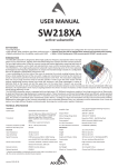
1
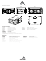
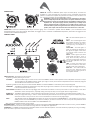
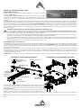
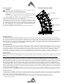
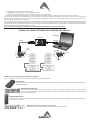
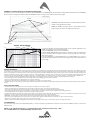
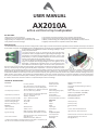
USER MANUAL
AX2010A
ac ve ver cal array loudspeaker
KEY FEATURES
• High output line array element
• Compact size, very good output-to-weight ra o
• High quality, low compression, low distor on HF driver
• Very stable horizontal coverage
• Transmission Line back loading for clean mid-bass reproduc on
• Natural sound Transmission Line HF projec on wave-forming device
• 96KHz / 40 bit floa ng point CORE processing with PRONET remote control
• Digitally controlled Class D amplifier module with SMPS
INTRODUCTION
The AX2010A Ver cal Line Array element is designed for a wide range of sound reinforcement applica ons where a flexible and easy to use ver cal
array systems is needed. The AX2010A has been designed both for rental live sound applica ons and for fixed installa ons and has been engineered
for the simplest use possible but without sacrificing anything in sound
quality and performance.
The high frequency range is reproduced by two low-distortion
compression drivers, equipped with very light-weight diaphragms. Two
transmission line waveforming waveguides have been used to load
the HF drivers, in order to provide a detailed and natural sound and to
achieve a long-distance HF projec ng capacity.
The two 10” woofers employed in the reproduc on of the mid-bass
range are equipped with very light-weight cones. The lightness of the
diaphragm is furthermore improved by the use of aluminium voice
coil instead of conven onal copper. This ensure a fast reproduc on of
the mid range and of mid-bass musical passages, improving also the thermal capacity of the voice
coil and, consequently, controlling the overall power compression. The two 10” woofers are back
loaded by a short hybrid transmission line that minimizes the effect of the box resonances and eliminates the “boxy” mid-bass sound commonly
obtained from regular bassreflex enclosures. The crossover filter approach is based on a “Constant Power” technique. Thanks to a par cular phase
combina on between the two ways around the crossover frequency, this approach is able to provide a very stable horizontal coverage and a very
stable off-axys sound image, also minimizing unwanted effects around the crossover frequency. The further applica on of phase lineariza on
techniques, combined to constant power crossover, yield a linear phase response and a coherent me response. This allows for a natural percep on
of acous c instruments and voices and for an improved depth of the sound image.
TECHNICAL SPECIFICATION
AcousƟcal
System type
Line Array Element
Short Transmission Line LF Back Loading
Acous c Transmission Line HF Waveguide
Low frequency transducer
Two 10” (260 mm), 2.5” (64 mm) aluminium
voice coil, 16Ω each, paralleled
High frequency transducer
Two 1.4” drivers, 2.5” (64 mm) edgewound
voice coil, tanium diaphragm,
16Ω each, paralleled
Frequency response (±3 dB)
Horizontal Coverage Angle
Ver cal Coverage Angle
Maximum Peak SPL @ 1m
Electrical
Input Impedance
Input Sensi vity
75 Hz – 18 kHz (Processed)
110° (-6 dB)
10° (-6 dB)
131 dB
20 kΩ balanced
+4 dBu / 1.25 V
Signal Processing
CORE processing, 96kHz / 40bit floa ng
point SHARC DSP, 24 bit AD/DA converters
Direct access Controls
4 Presets: Standard, Long Throw, Down FillSingle Box, User.
Network Termina on, GND Link
* Nominal consumpƟon is measured with pink noise with a crest factor of 12
dB, this can be considered a standard music program.
Remote Controls
Network protocol
Amplifier Type
Output Power
Mains Voltage Range (Vac)
Mains Connector
Consump on*
IN / OUT Connectors
IN / OUT Network Connectors
Mechanical
Width
Height
Depth
Taper angle
Construc on
Paint
Suspension system
Front Suspension
Back Suspension
Net Weight
PRONET control so ware
CANBUS
Class D with Variable Switching Frequency
and SMPS
2x 1000 W
230 V~ ±15% or 115 V~ ±15% 50/60 Hz
PowerCon® (NAC3MPA + NAC3MPB)
700 W (nominal) 1700 W (max)
Neutrik XLR-M / XLR-F
ETHERCON® (NE8FAV)
746 mm (29.37”)
341 mm (13.42”)
530 mm (20.86”)
5°
15 mm, reinforced Phenolic Birch
High resistance, water based paint
Aluminium Fast Link structure with ¼ Fast Pin
High Strength Steel with ¼ Fast Pin
40.3 Kg (88.7 lbs.)
MECHANICAL DRAWING
746 mm
29.37”
341 mm
13.42”
230 mm
9.06"
530 mm
20.86”
5.0°
OPTIONAL ACCESSORIES
AXCASE02
Carrying Case for 2 box unit
USB2CAN
PRONET network converter
NAC3FCA
Neutrik Powercon® BLUE PLUG
KPTAX2012P
Fly bar for Axiom AX2010 Loudspeakers
NAC3FCB
Neutrik Powercon® WHITE PLUG
BOARDAC2P
M10 foot for stacked installa on
NE8MCB
Neutrik Ethercon PLUG
NC3MXXBAG
Neutrik XLR-M
NC3FXXBAG
Neutrik XLR-F
RAINCOV2010
Rain protec on for connectors
see www.proel.com for detailed descripƟon and other available accessories.
SPARE PARTS
95AXM014
Powercon® sockets kit with internal wiring
98AXM10WZ8
10’’ woofer - 2.5” VC
NAC3MPA
Neutrik Powercon® BLUE SOCKET
98DRI1424
1.4’’ - 2.5” compression driver
NAC3MPB
Neutrik Powercon® WHITE SOCKET
98MBN1424
95AXM014
Locking Pin for AX2010
PLG716
Straight Shackle 16 mm for Fly bar
91AMD2010
91CTRL2010
Power amplifier module with mechanical assembly
Input & DSP module with panel assembly
tanium diaphragm for 1.4” driver
POWER PANEL
MAINS IN - Powercon® NAC3FCA power input connector (blue). To switch the
amplifier on, insert the Powercon® connector and turn it clockwise into the ON
posi on. To switch the amplifier off, pull back the switch on the connector and
turn it counter-clockwise into the POWER OFF posi on.
WARNING! In the case of product failure or fuse replacement, disconnect
the unit completely from the mains power. The power cable must only be
connected to a socket corresponding to the specificaƟons indicated on the
amplifier unit. The power supply must be protected by a suitably rated
thermo-magneƟc breaker. Preferably use a suitable switch to power on
the whole audio system leaving the Powercon® always connected to each
speaker, this simple trick extend the life of the Powercon® connectors.
POWER OUT - Powercon® NAC3FCB power output connector (grey). This is connected in parallel with the MAINS ~ / IN. The maximum load
applicable depends on the mains voltage. With 230V~ we suggest to link a maximum of 4 AX2010A loudspeakers, with 120V~ we suggest to link
a maximum of 2 AX2010A loudspeaker.
CONTROL PANEL
ON - This LED indicates power on
status.
PROT - This red LED lights when
the amplifier module is in protect
mode for an internal fault and,
consequently, the amplifier is
muted.
SIGN LIMIT - This LED lights in
green to indicate the presence of
the signal and lights in red when
an internal limiter reduces the
input level.
INPUT - Audio signal input with
locking XLR connector. It has a
fully electronically balanced
circuitry including AD conversion
for the best S/N ra o and input
headroom.
LINK - A direct connection from
the input connector to link other
speakers with same audio signal.
GND LIFT - This switch lift the
ground of the balanced audio
inputs from the earth-ground of
the amplifier module.
PRESET BUTTON - This bu on has two func on:
1) Pressing it while powering on the unit:
ID ASSIGN
the internal DSP assigns a new ID to the unit for the PRONET remote control opera on. Each loudspeaker must have a unique
ID to be visible in the PRONET network. When you assign a new ID, all the other loudspeakers with the ID already assigned
must be ON and connected to the network.
2) Pressing it with the unit ON you can select the DSP PRESET. The selected PRESET is indicated by the corresponding LED:
STANDARD
This PRESET is suitable for ver cal flown arrays that may range from 4 to 8 boxes or for the centre region of a bigger flown array.
It can be used also for stacked arrays.
LONG THROW This PRESET can be used in arrays bigger than 6 or 8 boxes and loaded in the top 1 or 2 boxes in order to obtain a more even
distribu on of the sound pressure, especially if they point very far away or to the upper deck of a large theatre.
DOWN FILL / This PRESET, which features a much smoother high frequency response, can be loaded in the bo om boxes (usually 1 or 2
SINGLE BOX boxes) of a large flown array, in order to reach conveniently the audience close to the stage. This preset could be very useful
also when the box is used just on its own as a Front Fill element in the front of very large stages.
USER
This LED lights when the USER PRESET is loaded. This preset corresponds to USER MEMORY no. 1 of the DSP and, as a factory
se ng, it’s the same to STANDARD. If you want to modify it, you have to connect the unit to a PC, edit the parameters with
PRONET so ware and save the PRESET into USER MEMORY no. 1.
Note: see also the example further on this manual.
NETWORK IN/OUT - These are a standard RJ45 CAT5 connectors (with op onal NEUTRIK NE8MC RJ45 cable connector carrier), used for PRONET
network transmission of remote control data over long distance or mul ple unit applica ons.
TERMINATE - In a PRONET network the last loudspeaker device must be terminated (with an inner load resistance) especially in a long run cabling:
press this switch if you want to terminate the unit.
AIMING and SUSPENDING INSTRUCTIONS
PREDICTION: EASE Focus 1
To aim correctly a complete system PROEL suggests to use always the Aiming
So ware - EASE Focus 1:
The EASE Focus 1 Aiming SoŌware is a two-dimensional, acous c simula on
so ware that serves for the configura on and modelling of Line Arrays close to
reality. It only considers the direct field, created by the complex addi on of the sound contribu ons of the individual loudspeakers or array
components.
The design of EASE Focus is targeted at the end user. It allows the easy and quick predic on of the array performance in a given venue. The scien fic
base of EASE Focus stems from EASE, the professional electro- and room acous c simula on so ware developed by AFMG Technologies GmbH. It
is based on the EASE Focus 1 system defini on files (Proel_AXIOM_AX2010P.EFO) required for its use. The EFO file contains the data that defines
the Line Array with regard to its possible configura ons as well as to its geometrical and acous cal proper es. For detailed explana on of how to
use the so ware and how to obtain a correct aiming refer to EASE Focus documenta on and other on-line manuals (h p://focus.afmg.eu/index.
php/Focus_1.html).
WARNING! CAREFULLY READ THE FOLLOWING INSTRUCTIONS AND CONDITION OF USE:
• This loudspeaker is designed exclusively for Professional audio applica ons. The product must be installed by qualified personal only.
• Proel strongly recommends that this loudspeaker cabinet be suspended taking into considera on all current Na onal, Federal, State and
Local regula ons. Please contact the manufacturer for further informa on.
• Proel do not accept any liability for damage caused to third par es due to improper installa on, lack of maintenance, tampering or
improper use of this product, including disregard of acceptable and applicable safety standards.
• During assembly pay a en on to the possible risk of crushing. Wear suitable protec ve clothing. Observe all instruc ons given on the
rigging components and the loudspeaker cabinets. When chain hoists are in opera on ensure that there is nobody directly underneath or
in the vicinity of the load. Do not under any circumstances climb on the array.
KPTAX2012P Fly Bar and accessories
The AX2010 Systems are built to allow the suspension of array with variable shape and dimensions. Thanks to a suspension mechanism designed
to be func onal, flexible and safe, each system must be suspended or stacked using the KPTAX2012P fly bar. The loudspeakers are linked together
in a column using a series of couplers integrated in the frame of each enclosure. Each system is set up properly both acous cally and mechanically
only using the aiming so ware.
Coupling system in the front does not require any adjustment: using two locking pins, each loudspeaker box is fixed to the previous. The slo ed
bar in the back is inserted in a U-shaped frame which features a series of numbered holes. Sliding the slo ed bar in the U-shaped frame of the
next loudspeaker and inser ng a locking pin in one of the numbered holes, it is possible to adjust the rela ve splay angle between two adjacent
loudspeakers in the array column.
KPTAX2012P fly bar maximum capacity is 700 Kg (1540 lbs) with the 0° angle. It can support up to 12 AX2010 loudspeakers with a safety factor
of 7:1.
KPTAX2012P FLY BAR AND ACCESSORIES
M10 FOOT FOR
STACKED INSTALLATION
(OPTIONAL)
KPTAX2012P FLY BAR ASSEMBLY SEQUENCE
STRAIGHT SHACKLE 16mm
1
IDENTIFICATION AND
DATA LABEL
5
1
2
FRONT BOX
PIN ATTACHMENT
3
SUSPEND HOLE
INDICATOR
SUSPEND HOLES
2
FRONT BOX
PIN ATTACHMENT
REAR BOX
PIN ATTACHMENT
4
Follow the sequence in the figure for fixing the fly bar at the first box. Usually
this is the first step before li ing up the system. Be careful to insert properly
all the locking pins (2)(3) and the shackle (5) in the right holes as specified by
the aiming so ware.
When lifting the system always proceed gradually step by step, paying
a en on to secure the fly bar to the box (and the box to the other boxes)
before pulling up the system: this makes easier to insert properly the locking pins. Also when the system is released down, unlock gradually the
pins.
During the li ing be very careful to not let the cables enter the space between one enclosure and the other, as their compression could cut
them.
Fly bar suspension and angle setup (centre of gravity)
The first figure shows where the normal centre of gravity is with one box or several boxes arranged in a line. Usually the boxes are arranged to
make an arc for the best coverage of the audience, so the center of gravity moves backward. The aiming so ware suggests the ideal suspension
pinpoint taking into account this behaviour: fix the straight shackle in this posi on.
KPTAX2012P FLY BAR FOR FLOWN ARRAY
KPTAX2012P FLOWN PINPOINT
SINGLE PINPOINT FOR
STRAIGHT SHACKLE
Note that the ideal aiming angle o en doesn’t correspond to the pinpoint: there
is o en a li le difference between ideal aiming and real aiming and its value is
the remaining angle: posi ve remaining angle can be adjusted a li le using two
ropes, nega ve remaining angle are self adjusted a li le because the cables
weighs on the back of the array. With some experience it’s possible to consider
preven vely these required li le adjustments.
CENTRE OF GRAVITY
During the flown set up you can connect the elements of the array to their cables.
We suggest to discharge the weight of the cables from the flying pinpoint by tying them with a tex le fibre rope, instead of le ng them hang
freely: in this way the posi on of the array will be much more similar to the simula on produced by the so ware.
Pin locking and splay angles set up
The figure below shows how to insert correctly the locking pin and how to set up the splay angle between loudspeakers.
95AXM014 LOCKING PIN
LOUDSPEAKER SPLAY ANGLES SET UP
HINGE BAR OF PREVIOUS BOX
Odd degrees
LOCK THE PIN IN THE
HOLE TO OBTAIN THE
REQUIRED SPLAY
ANGLE.
press and
insert
3° >
5° >
release and
lock
7° >
9° >
Degrees
indicator >
1° STEP HOLE
0,5° STEP HOLE
0°
1°
2°
1° >
Block cam
hole >
Even degrees
3°/0,5°
< 2°
< 4°
< 6°
< 8°
4°/1,5°
5°/2,5°
6°/3,5°
Pin
7°/4,5°
8°/5,5°
9°/6,5°
10°
< 10°
< 0°/10°
< 0,5°/6,5°
USE THIS HOLE TO
LOCK THE HINGE BAR
WHEN THE LOUDSPEAKER
IS REST
Block cam
hole
Wind loads
When planning an open-air event it is essen al to obtain current weather and wind informa on. When loudspeaker arrays are flown in an open-air
environment, possible wind effects must be taken into account. Wind load produces addi onal dynamic forces ac ng on the rigging components
and the suspension, which may lead to a dangerous situa on. If according to the forecast wind forces higher than 5 b (29-38 Km/h) are possible,
the following ac ons have to be taken:
- The actual on-site wind speed has to be monitored permanently. Be aware that wind speed typically increases with height above ground.
- Suspension and securing points of the array should be designed to support double the sta c load in order to withstand any addi onal dynamic
forces.
WARNING!
Flying loudspeakers overhead at wind forces higher than 6 b (39-49 Km/h) is not recommended. If the wind force exceeds 7 b (50-61
Km/h) there is a risk of mechanical damage to the components which may lead to a dangerous situa on for persons in the vicinity of the
flown array.
- Stop the event and make sure that no person remains in the vicinity of the array.
- Lower and secure the array.
Stacked installaƟon
KPTAX2012P STACKED ARRAY
WARNING!
• The ground where the KPTAX2012P Fly bar serving as ground support is
placed needs to be absolutely stable and compact.
• Adjust the feet so to lie the bar perfectly horizontal.
• Always secure ground stacked setups against movement and possible
pping over.
• A maximum of 4 x AX2010 cabinets with the KPTAX2012P Fly bar serving
as ground support are allowed to be set up as ground stack.
max splay angle 10°
In the stack configura on you have to use the three op onal BOARDAC2P feet and
the fly bar must be mounted upside down on the ground.
Coupling system in the front do not require any adjustment: using two locking pins
each loudspeaker box is fixed to the previous. The slo ed bar in the back is inserted
in a U-shaped frame which features a series of numbered holes. Sliding the slo ed
bar in the U-shaped frame of the next loudspeaker and inser ng a locking pin in
one of the numbered holes, it is possible to adjust the rela ve splay angle between
two adjacent loudspeakers in the array column.
The op mal splay angles can be simulated using the EASE Focus 1 so ware.
max splay angle 10°
max splay angle 10°
max splay angle 5°
CENTER OF GRAVITY
POWER AMPLIFIERS
The AX2010A is powered by DA SERIES digital power modules, a new genera on of CLASS D power amplifier with digitally-controlled SMPS.
The innova ve technology used for these amplifiers (including also the use of a variable switching frequency) offers performances at the top of
the range, such as a superior sound defini on at any audio frequency, very high dynamics also for low level signals and very low distor on even at
the maximum power The superior sound quality can be compared with top-of-the-range AB-class analog systems, while the DA modules feature
a higher dynamics, very compact size and light weight and efficiency above 90%. The DA module employed for powering the AX2010A deliver in
an ultra-compact package a maximum power of 2000W.
SIGNAL PROCESSING
The system processing is based on the CORE DSP pla orm, which has been designed by the PROEL R&D Laboratories using one of the most
advanced SHARC DSP for audio applica on. It features 40bit, 96kHz floa ng point resolu on and high quality 24bit AD/DA converters, for a perfect
signal integrity, a dynamic range in excess of 110dB and a superior sonic performance. Thanks to its massive processing power, the CORE pla orm
is capable of providing the most sophis cated algorithms for speaker processing, together with remote control and networking capability.
The PRONET control so ware, working on a solid and reliable CANBUS based network protocol, provides an intui ve interface for the remote
control of the whole system, with the possibility of eqing, delaying, increasing the protec ons and monitoring the status of the amplifier.
PRONET Network
PRONET so ware has been developed in collabora on with sound engineers and sound designers, in order to offer an “easy-to-use” tool to setup
and manage your audio system. With PRONET you can visualize signal levels, monitor internal status and edit all the parameters of each connected
device.
You can ownload the PRONET so ware from the PROEL website at h p://www.proel.com (click on the link in the AX2010A product page).
The AXIOM ac ve loudspeaker devices can be connected in a network and controlled by the PRONET so ware. For the network connec on the
PROEL USB2CAN converter op onal accessory is needed. The first me you connect a device with the USB2CAN converter, Windows O.S. will ask you
to install the driver files, which you can find in the Driver folder within the Pronet applica on folder (by default is C:\Program Files\Proel\Pronet\
Driver, or if you changed it <your path>\Driver). Please refer also to “Installa on” and “Drivers” paragraphs in the Pronet documenta on.
The PRONET NETWORK is based on a robust, reliable and fast communica on protocol called CANBUS. The devices in a PRONET NETWORK are
connected together with a “linear bus topology”. The USB2CAN converter must be connected to the network input of the first device, the network
output of the first device is connected to the input of the second and so on. For the network connec ons simple RJ45 cat.5 or cat.6 ethernet
cables can be used (please don’t confuse a ethernet network with a PRONET network these are completely different and must be fully separated
also both use the same kind of cable).
The beginning and the end of a PRONET NETWORK must be terminated. One side is terminated by the USB2CAN converter, the other side must
be terminated pressing the TERMINATE switch on the last device. All devices between these two points must have the TERMINATE switch li ed.
Assign the ID number
To work properly in a PRONET network each connected device must have a unique iden fier number, called ID. By default the USB2CAN PC
controller has ID=0 and there can be only one PC controller. Every other device connected must have its own unique ID equal or greater than 1:
in the network cannot exist two devices with the same ID.
An ID number is assigned automa cally to each devices when they are turned on for the first me connected to a network.
In order to correctly assign a new available ID to each device for working properly in a Pronet network, follow these instruc ons:
1. Switch off all the devices.
2. Connect them correctly to the network cables.
3. “TERMINATE” the latest device in the network connec on.
4. Switch on the first device keep pressed “PRESET” bu on on the control panel.
5. Leaving the previous device switched on, repeat the previous opera on on the next device, un l the latest device is turned on.
The “Assign ID” procedure for a device makes the internal network controller to perform two opera ons: reset the current ID; search the first free
ID in the network, star ng from ID=1. If no other devices are connected (and powered on), the controller assume ID=1, that is the first free ID,
otherwise it searches the next one le free.
These opera ons ensure that every device has it’s own unique ID, if you need to add a new device to the network you simply repeat the opera on
of step 4. Every device maintains its ID also when it is turned-off, because the iden fier is stored in the internal memory and it is cleared only by
another “Assign ID” step, as explained above. This means that if your network is made always of the same devices the assigning ID procedure must
be executed only the first me the system is turned on.
For more detailed instrucƟon about PRONET see the PRONET USER’S MANUAL included with the soŌware.
EXAMPLE OF PRONET NETWORK WITH AX2010A AND SW218A
PC NOTEBOOK
USB2CAN
USB 2.0 port
STATUS
CONVERTER
USB2CAN
CODE:
USB2CAN
S/N:
00001
RATINGS: 5V --- 200mA
RoHS COMPLIANT
MADE IN ITALY
network
do not
pressed
last device
pressed
AX2010A
network
Useful tools to set up properly a verƟcal array system
This is a list of tools that can be very useful to set properly a ver cal array system.
CABLE TESTER
It is a good prac ce to check all cables before each installa on, because even one faulty cable can compromise heavily the
system performance.
INCLINOMETER WITH LEVER
This tool can be used to verify the ver cal array angle. It can be used at the top or at the bo om of the array In this
case you have to sum all splay angles, so the maximum precision is needed for aiming the ver cal array, par cularly
for long throw applica ons.
LASER DISTANCE METER
This instrument can be useful to measure the height of the ver cal array and to know the distance between FOH-Subs and FOH-Array
for se ng the delay me.
SMAART or similar acousƟc measurement system
These are useful to measure delays, phase and response of the system.
EXAMPLE OF INSTALLATION IN A THEATRE WITH BALCONY
Here below you can see an example of the use of different PRESETS in an AX2010 flown array installed in a big theatre with balcony. The TOP BOXES
of the array are aiming at the balcony while the DOWN FILL box is aiming at the audience close to the stage.
TOP BOX
TOP BOXES: the power level at the end of the balcony is lower,
as well as the high frequency level.
DOWN FILL BOXES: the power level in the proximity of the
stage is higher, as well as the high frequency level.
DOWN FILL BOX
AX2010A - PRESET RESPONSE
+15
STANDARD
SINGLE/DOWNFILL
dB
LONG THROW
In order to op mize the array performances for this specific applica on, the
PRESETS should be used in the following way.
Load the STANDARD preset in the central boxes.
Load the LONG THROW preset in the TOP 1 or 2 boxes, in order to compensate
the loss of power level and high frequencies of the program sent the upper
deck of the theatre.
Load the DOWN FILL / SINGLE BOX preset in the BOTTOM box in order to
smooth the high frequency content of the program sent to the audience close
to the stage.
+10
+5
0
-5
-10
-15
-20
-25
-30
-35
20
50
100
200
500
1K
2K
5K
10K
20K
Hz
LIMITED WARRANTY
Proel warrants all materials, workmanship and proper opera on of this product for a period of two years from the original date of purchase. If any defects are found
in the materials or workmanship or if the product fails to func on properly during the applicable warranty period, the owner should inform about these defects the
dealer or the distributor, providing receipt or invoice of date of purchase and defect detailed descrip on. This warranty does not extend to damage resul ng from
improper installa on, misuse, neglect or abuse. Proel S.p.A. will verify damage on returned units, and when the unit has been properly used and warranty is s ll
valid, then the unit will be replaced or repaired. Proel S.p.A. is not responsible for any “direct damage” or “indirect damage” caused by product defec veness.
• This unit package has been submi ed to ISTA 1A integrity tests. We suggest you control the unit condi ons immediately a er unpacking it.
• If any damage is found, immediately advise the dealer. Keep all unit packaging parts to allow inspec on.
• Proel is not responsible for any damage that occurs during shipment.
• Products are sold “delivered ex warehouse” and shipment is at charge and risk of the buyer.
• Possible damages to unit should be immediately no fied to forwarder. Each complaint for package tampered with should be done within eight days from product
receipt.
SAFETY INSTRUCTIONS
– To reduce the risk, close supervision is necessary when the product is used near children.
– Protect the apparatus from atmospheric agents and keep it away from water, rain and high humidity places.
– This product should be site away from heat sources such as radiators, lamps and any other device that generate heat.
– This product should be located so that its loca on or posi on does not interfere with its proper ven la on and hea ng dissipa on.
– Care should be taken so that objects and liquids do not go inside the product.
– The product should be connected to a power supply mains line only of the type described on the opera ng instruc ons or as marked on the product. Connect the
apparatus to a power supply using only power cord included making always sure it is in good condi ons.
– WARNING: The mains plug is used as disconnect device, the disconnect device shall remain readily operable.
– Do not cancel the safety feature assured by means of a polarized line plug (one blade wider than the other) or with a earth connec on.
– Make sure that power supply mains line has a proper earth connec on.
– Power supply cord should be unplugged from the outlet during strong thunderstorm or when le unused for a long period of me.
CE CONFORMITY
Proel products comply with direc ve 2004/108/EC (EMC), as stated in EN 55103-1 and EN 55103-2 standards and with direc ve 2006/95/CE (LVD), as stated in EN
60065 standard.
PROEL S.p.A. (World Headquarter) - Via alla Ruenia 37/43 - 64027 Sant’Omero (Te) - ITALY
Tel: +39 0861 81241 Fax: +39 0861 887862 www.proel.com