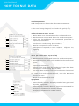
1
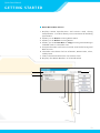
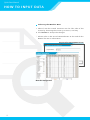
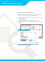
HEAT LOAD
CALCULATING TOOL
QUICK START MANUAL
Disclaimer Of Warranty On Software
The software provided with this Manual is given to you “as is” without warranty of any kind, either
expressed or implied, including but not limited to the implied warranties of merchantability and
fitness for a particular purpose. Emerson Climate Technologies does not warrant, guarantee, or
make any representations regarding the use or the results of the use of the Software Program in
terms of its correctness, accuracy, reliability, newness, or otherwise. In addition, Copeland does
not warrant that the functions contained in the Software Program will meet your requirements
or that the operation of the Software Program will be un-interrupted or error free. The entire
risk as to the quality, results and performance of the Software Program is assumed by you. Some
jurisdictions do not allow the exclusion of implied warranties so the above exclusion may not
apply to you.
Quick Start Manual
INTRODUCTION
This sof t ware is developed by Emerson
Climate Technologies to assist in calculation
of heat of any building. It has weather data
of 44 countries in Asia.
Easy step -by-step
input of building parameters allows OEMs
sales engineers to calculate the precise load
requirement and help them decide on an
optional system for building.
Quick Start Manual
ABOUT THE MANUAL
This Manual aims to provide the user sufficient
information about the use of the Heat Load Calculating
Tool® (HLCT) developed by Emerson Climate Technologies.
With the aid of this tool, engineers can compute the Heat
Load of any building and provide a summary of all Heat Load
Computations.
This Manual will help the user quickly adapt to the HLCT
environment by providing step-by-step instructions on how
to design a project, how to properly input data, and how to
preview and print the summary of results.
H eat Loa d C al culatin g Too l
Q u ick St ar t Man ual
Disclaimer
Introduction
About the Manual
Contents
Software Installations / Key Generation
How to Use the Manual
User Environment and Interface
How to Enter Data
Creating a New Project……….................………………............15
Selecting Weather Data……………………................…...........16
Entering Room Specification.…..…………................………….18
Adding a New Room ………………………….............………......19
Calculating Conductivity Factor (k)…….................……........21
Material Selection...………….…………..............………….........22
Calculate New Composite Material.…………...............……...24
Adding New Material to List.………..............……………………25
Design Room Temperature and Humidity…................….….26
Load Time Scheduling……………..............………...................27
Outside Wall, Outside Glass, Inside Wall Input Data ...........29
Supplementary Load ………….......……………………...............30
How to Print / Preview Data
List of all the factors / Nomenclature / symbols used
Emerson Climate Technologies contact information /
Technical Support
Glossary
Index (Nomenclature)
Heat Load
Quick
StartCalculator
Manual User Manual
HOW TO USE THIS MANUAL
The following pages cont ain ac tual HLC T environment pic tures
that will visuall y assis t the user throughout the cour se of
the Manual. For common under s t anding, please refer to the
figure below. The colored pic ture cor responds to the ac ti ve
screen, w hile the black and w hite pic ture cor responds to the
root or previous screen.
HLCT Main Screen
Project Information Main Screen
Technical Suppor t
For queries regarding the Heat Load Calculating Tool, please
send us an e-mail at:
[email protected]
Or visit us at http://www.digitalscroll.com/
Heat Load
Quick
StartCalculator
Manual User Manual
SOF T WARE INSTALL ATION
Installing your HLCT
To ins t all the H eat Loa d C al culatin g Too l® ver sion 2.0,
you mus t have adminis trati ve pr i vileges. This s tep -by -s tep
Manual will walk you through the ins t allation process with
ease.
Step 1. Inst allatio n Set-U p
Af ter opening the ins t aller, you will see the H eat Load
C alculating Tool Setup Main Screen. Read each page and
then click on the Nex t button to be direc ted through each
process.
Step 2. License Agr eem ent
Read through the Ter ms and Conditions outlined in the End
User License Agreement . Click Nex t to agree and proceed
with the ins t allation.
Step 3. User Info rmatio n
Ty pe your name and your company name.
proceed with the ins t allation.
Click Nex t to
Heat Load
Quick
StartCalculator
Manual User Manual
SSOF
O F T WARE
WA R E IINSTALL
N S TA L L ATION
AT I O N
Step 4. Ch oosin g D estinatio n Loc atio ns
B y default , your H eat Load C alculating Tool will be ins t alled in
you r Programs F ile folder located on your C: dr i ve. To change
this, click on Change, then click on Nex t to proceed with the
ins t allation.
Step 5. St ar t of Inst allatio n
This will confir m all set up infor mation and proceed with
the sof t ware ins t allation. Click on Nex t to proceed with the
ins t allation.
Step 6. Inst allatio n Pr ogr ess
The ins t aller program will begin adding the H eat Load
C alculating Tool to your computer. D o not inter r upt the
ins t allation until it is complete.
Step 7. En d of Inst allatio n
The H eat Load C alculating Tool has been loaded and read y for
use. To e xit the ins t allation set up, click on Finish .
Heat Load
Quick
StartCalculator
Manual User Manual
K E Y R E G I S T R AT I O N
Ac tivatin g yo ur HLC T
For ac ti vation, please see ins tr uc tions as s t ated in the
Ac ti vation Screen shown below :
Heat Load
Quick
StartCalculator
Manual User Manual
G E T T I N G S TA R T E D
User Envir o nm ent an d Inter fa ce
H eat Loa d C al culatin g Too l Main Scr een
1. Creates a new Projec t
2. O pens an e xis ting .mdbe Projec t
3. Saves all cur rent Projec t Infor mation
4. Resets all cur rent Projec t infor mation in the H eat Load C alculating Tool dat abase
5. O pens the Pr ojec t Inf ormation Screen
6. O pens the Room Data Screen
7. O pens the Preview and Print Screen
8. O pens the About Screen
9. O pens the Help Screen and a Sample Projec t Manual
10.Closes the H eat Load C alculator
2
3
4
8
9
10
1
5
6
7
10
Heat Load
Quick
StartCalculator
Manual User Manual
G E T T I N G S TA R T E D
Pr ojec t Info rmatio n Main Scr een
1. O pens the Weather Dat a of 44 countr ies in A sia.
2. Allows you to Change the Weather Dat a of the chosen
C it y.
3. Accepts the Dat a and retur ns to the H eat Load C alculating
Tool Main Screen
1
2
3
11
Heat Load
Quick
StartCalculator
Manual User Manual
G E T T I N G S TA R T E D
Roo m Dat a Main Scr een
1. Displays Room Specification and Fac tor s used dur ing
Comput ation. This also allows you to cus tomize all building
parameter s.
2. Allows you to Revise e xis ting Room Dat a
3. Allows you to Dele te e xis ting Room
4. Allows you to Create New or Copy Exis ting Room D esigns
and add them in the O rder Lis t
5. Accepts the Dat a and retur ns to H eat Load C alculating Tool
Main Screen
6. The O rder Lis t shows the lis t of Rooms, Room name, Floor,
and Sys tem
7. F ilter s the Rooms based on the chosen Floor
8. Displays the Room Number of selec ted Room
7
8
6
1
2
3
4
5
12
Heat Load
Quick
StartCalculator
Manual User Manual
G E T T I N G S TA R T E D
Print / Pr eview Main Scr een
1. Sets the St andard units to be used dur ing comput ation
and dur ing pr inting
2. Selec ts the items to be viewed and pr inted
3. D ocument ation and D et ails
4. Pr ints the cor responding hour s reflec ted in the T ime
Schedule screen
5. Displays Comput ation Results
6. Accepts the Dat a and retur ns to the H eat Load C alculating
Tool Main Screen
1
2
3
4
5
13
6
Heat Load
Quick
StartCalculator
Manual User Manual
H O W T O I N P U T D ATA
Starting a Project
You can s t ar t a projec t by either creating a N ew Projec t or
opening an e xis ting .mdbe projec t .
Cr eatin g a N ew Pr ojec t
1. Click New to s t ar t a N ew Projec t . This opens the Projec t
Infor mation Screen.
2. F ill up the Projec t Name and Projec t address
3. B y Clicking O ther Cities , you can either choose or cus tomize
weather dat a
HLCT Main Screen
Project Information Main Screen
14
Heat Load
Quick
StartCalculator
Manual User Manual
H O W T O I N P U T D ATA
Sel ec tin g th e Weath er Dat a
1. Selec t from the Lis ted Locations on the lef t side of the
screen by choosing the Countr y, Province, and C it y
2. Click Selec t to accept the changes
* Please refer to the Lis t of N omenclature at the end of this
Manual for more infor mation.
Project Information Main Screen
Weather Design Data
15
Heat Load
Quick
StartCalculator
Manual User Manual
H O W T O I N P U T D ATA
Sel ec tin g th e D esign Dat a
1. From the Projec t Infor mation Screen, click Design Data
2. B y choosing Revise , you can change the dat a in the
spreadsheet by simpl y clicking on the cells
3. To accept the changes, click Confirm. To close the window
without saving the dat a, click Exit .
Design Data
16
Heat Load
Quick
StartCalculator
Manual User Manual
H O W T O I N P U T D ATA
In p u t of Roo m Sp eci fic atio ns
A large por tion of all H eat Load Comput ations is based on the
parameter s entered in this par t of the program.
Room Specifications include Building Mater ial Charac ter is tic,
Fac tor s, D esign Room Temperature, T ime, other Sources of
H eat , and more.
* Please refer to the Lis t of N omenclature at the end of this
Manual for more infor mation.
HLCT Main Screen
Room Data Main Screen
17
Heat Load
Quick
StartCalculator
Manual User Manual
H O W T O I N P U T D ATA
Add in g a N ew Roo m
B y choosing Add from the Room Dat a Main Screen, you can
inser t a new Room to your cur rent Projec t . Completel y fill up all Room Specification D et ails.
Room’s Specification:
a. Identifies the Room number. It also cor responds to the
order that the Room was created.
b. The name of the Room
c. The Floor w here the Room is located
d. Common air conditioning s ys tem being used by multiple
conditioned Rooms
e. The specific f unc tion of the Room
f. Floor Area of the Room in metr ic units (sq.m)
g. Ceiling height of the Room in metr ic units (m)
Room Data Main Screen
b
a
e
f
g
c
d
Room Specification Main Screen
18
Heat Load
Quick
StartCalculator
Manual User Manual
H O W T O I N U T D ATA
Load Components:
Load Components are factors that affect Heat Transmissions.
If unconditioned areas are located above, below, or adjacent
to the room being designed, heat loads will greatly vary.
Ceiling (in metric units, sq.m)
a. Boiler Room area located above the conditioned space
b. Kitchen Room area located above the conditioned space
c. Floor area located above the conditioned space that is
exposed to outside air
d. Interior floor area above the conditioned space that does
not have air conditioning. (Ex. Corridors)
e. Roof Area exposed to solar radiation
f. Skylight area exposed to solar radiation. Skylights are
windows set into a ceiling or roof that provide natural
lighting.
a
b
c
d
e
f
Floor (in metric units, sq.m and m)
a. Boiler Room area located below the conditioned space
b. Kitchen Room area located below the conditioned space
c. Unconditioned car park area located below the conditioned
space
d. Floor area located below the conditioned space that is
exposed to outside air
e. Interior floor area below the conditioned space that does
not have air conditioning. (Ex. corridors)
f. For Lower Floor without basement levels, enter the Ground
or Earth area under Lower Floor
For Lower Floor with basement levels, enter the Basement
Level Floor area
g. Depth of each Basement Level
a
b
c
d
e
f
g
Equipment
a
b
c
d
19
a. Inter nal loads brought about by sensible heat generated
by indoor equipment
b. Inter nal loads brought about by latent heat generated by
indoor equipment
c. Accept able allowance for Sensible heating
d. Accept able allowance for L atent heating
Heat Load
Quick
StartCalculator
Manual User Manual
H O W T O I N P U T D ATA
C al culatin g th e Co n duc tivit y Fa c to r (k)
This por tion of the calculator allows you to selec t or cus tomize
the t y pe of mater ial that makes up the s tr uc tural wall, roof,
ceiling, floor and other s.
The Conduc ti vit y fac tor denoted by k is measured as:
kcal
m 2-hr- o C
The Shielding coefficient for Sk y lights and glass is denoted
by S c and S c (RF).
Conductivity Factor Main Screen
20
Heat Load
Quick
StartCalculator
Manual User Manual
H O W T O I N P U T D ATA
Material Sel ec tio n fo r Walls , Roof, Fl oo r s an d Cei lin gs
B y choosing Selec tion , you can choose from the HLC T
dat abase specific cons tr uc tion t y pes of var ious walls, roof s,
floor s, and ceilings.
1. Selec t composite mater ial from the roll -down menu
2. Equi valent k values and s tr uc ture t y pe are automaticall y
displayed
3. Choose Selec t to accept the changes or Exit to ignore the
changes
Material Selection Screen
21
Heat Load
Quick
StartCalculator
Manual User Manual
H O W T O I N P U T D ATA
Material Selection for Skylight and Glass
By choosing Selection, you can choose from the HLCT database
specific construction types of Skylights and Outside Glass.
1. Select Window Type with its corresponding thickness from the
roll-down menu
2. Select Curtain Type
3. Equivalent K(OG) and Sc are automatically displayed
4. Choose Select to accept the changes or Exit to ignore the
changes
Material Selection (Glass) Screen
22
Heat Load
Quick
StartCalculator
Manual User Manual
H O W T O I N P U T D ATA
C al culate N ew Co m posite Material
B y choosing Calculation , you can create specific cons tr uc tion
composite mater ials that will make up the walls, roof s, floor s,
and ceilings.
Sample Composite Wall = T ile, Mor tar, Brick, Plas ter
1. Selec t from the mater ial lis t “ T ile”
2. Input the mater ial thickness “9mm”
3. To transfer the “ T ile” to the spreadsheet , click the Right
pointer arr ow.
To remove the “ T ile” from the spreadsheet , highlight the
“ T ile” entr y in the spreadsheet , and then click the Le f t
pointer arr ow
4. Continue dat a entr y for the following mater ials:
M or t ar – 40 mm
Br ick – 200 mm
Plas ter – 3 mm
5. Click Cal K to view the K results
6. Click Selec t to accept the changes
Calculation Screen
23
Heat Load
Quick
StartCalculator
Manual User Manual
H O W T O I N P U T D ATA
Add in g a N ew Material to th e List
In case the mater ial you need is not included in the Mater ial
Lis t , a new mater ial can be created.
1. Click Add and t y pe in the new mater ial name.
2. Enter the specific value of the new mater ial at the entr y
below the Mater ial Lis t .
3. To add the new mater ial to the Mater ial Lis t , click Conf.
To per manentl y remove any mater ial from the Mater ial
Lis t , highlight the mater ial and click Del .
4. Click Selec t to accept the changes.
Calculation Screen
24
Heat Load
Quick
StartCalculator
Manual User Manual
H O W T O I N P U T D ATA
D esign Roo m Tem p eratur e an d H umid it y
B y choosing Temperature/Humidit y , you can change the
temperature ( o C) and RH (%) that the conditioned space is
designed to maint ain under the mos t e x treme conditions.
1. Enter the Summer D esign Temperature
2. Enter the Summer D esign Relati ve Humidit y
3. Enter the W inter D esign Temperature
4. Enter the W inter D esign Relati ve Humidit y
5. Click Confirm to accept the changes
6. To reset the dat a to D efault D esign Values, click Back to
Prese t
Design Room Temperature
Humidity Main Screen
25
Heat Load
Quick
StartCalculator
Manual User Manual
H O W T O I N P U T D ATA
Load Time Scheduling
By choosing Time Schedule, you can assign the amount of internal
heat (percentage, %) produced during particular time periods.
a. Operation Time denotes the exact hours when Lights, People or
Equipment generate internal heat
b. Internal Heat Distribution Table:
Column – Amount of Internal Heat generated by Lights, People,
Indoor Equipment and its equivalent Time. (1-24 th
hour 1 AM-12 Midnight)
Row
– Hourly Time Period
c. To accept the new Operation Time, click Timing Change
d. To reset the data to Default Design Values, click Back to Preset
e. To input new internal heat percentages, click Figure Change
f. Click Confirm to accept the changes
Time Schedule Main Screen
b
a
c
d
e
f
26
Heat Load
Quick
StartCalculator
Manual User Manual
H O W T O I N P U T D ATA
Sam p l e Internal H eat Gain Distribu tio n:
8-18 Hour, 50% Internal Heat Gain
19-24 Hour, 100% Internal Heat Gain
1. Change D efault O peration T ime, from “8:00 – 18:00” to
“8:00-24:00”
2. To accept the new time, click T iming Change
3. To manuall y change the percent ages, click Figure Change.
Input “50” on the cells under Lights, People, and Equipment
and dur ing the time per iod “8:00-18:00”
Time Schedule Main Screen
27
Heat Load
Quick
StartCalculator
Manual User Manual
H O W T O I N P U T D ATA
O u tsid e Wall (OW), O u tsid e G lass (OG), Insid e Wall (IW)
In p u t Dat a
The position of the building in reference to the sun’s
or ient ation greatl y affec ts the amount of heat gained through
var ious sides of the building.
At each direc tion (N , NE, E, SE, S, S W, W, NW), wall and glass
dimensions (length and height) are measured in meter s (m).
a. Dimension of outside wall
b. Dimension of outside wall in ear th
U nderground wall depth from the ground level
c. Dimension of outside glass
d. Dimension of inter nal wall
e. Indicates w hether the inter nal wall is adjacent to a boiler
room, kitchen, or a room facing outdoor air
If the inter nal wall is not adjacent to any of these rooms,
use the option “l ocated in interior area ”
f. Choose Selec t to accept the changes
g. Choose Exit to ignore the changes
OW/OG/IW Input Data Main Screen
a
b
c
d
e
f
g
28
Heat Load
Quick
StartCalculator
Manual User Manual
H O W T O I N P U T D ATA
O th er / Su p p l em ent ar y Loa d
In addition to the heat transmitted into the conditioned
space through walls and air infiltration, any heat gain from
other sources mus t be included in the tot al cooling / heating
load comput ation.
The infiltration air amount , power consumptio n from
lighting, and people -generated heat is direc tl y affec ted by
the f unc tion of each room.
a. Ty pe of Ventilation Sys tem to be ins t alled
b. The amount of fresh air required for building occupants
c. Tot al H eat Exchanger Efficienc y; St andard tot al heat
e xchanger efficienc y is 60%
d. Amount (percent age) of infiltrated air dur ing Summer and
W inter months
St andard air infiltration is 0.2 time air changes of tot al room
air volume.
e. Power consumption of lighting equipment measured in
Watt/sq.m.
f. Power consumption for equipments that consume power
24 hour s each day (Guaranteed Equipment heat)
g. The reasonable number of per sons occupying the floor
based on the declared floor area and specific room
f unc tion
h. Amount of sensible and latent heat generated by the
occupants
a
b
c
d
e
f
g
h
i
29
j
k
Heat Load
Quick
StartCalculator
Manual User Manual
PRINTING AND PREVIEW
V iewin g an d Printin g a Pr ojec t
The H eat Load C alculating Tool generates all the necessar y
heat load comput ation results allowing you to view and
review them s ys tematicall y.
B y choosing Preview/Print , you can either view or pr int the
projec t result summar y.
1. Selec t the unit (W or Btu/h) to be used.
2. Mar k w hich items to be viewed and pr inted.
3. F ill -up the Cover page det ails.
4. Enter the H our s that you wish to Preview and Pr int . These T imes cor respond to the Inter nal H eat Gain Percent age
T ime Schedule
5. Choose Preview/Print to display the summar y of the
results
6. Choose Exit to ignore the changes
HLCT Main Screen
1
2
3
4
6
5
Preview / Print Main Screen
30
Heat Load
Quick
StartCalculator
Manual User Manual
PRINTING AND PREVIEW
From the selec tion, click on the buttons you want to preview
and pr int .
1. Cover Page
2. Sys tem Table
3. Room Peak Load
4. Room Dat a D et ails
5. Room Dat a (Walls)
6. Sys tem Peak Load
7. Room Load Cooling
8. Room Load H eating
9. Building Load
Preview / Print Main Screen
Summary of Results
31
Heat Load
Quick
StartCalculator
Manual User Manual
GLOSSARY
Summer DB
Summer Dry Bulb Temperature
°C
The ambient or outdoor summer temperature
samples for each country/city.
Summer RH
Summer Relative Humidity
%
The summer relative humidit y in relation to the
Summer DB and atmospheric pressure.
Ratio of water vapor in the air in relation to the
amount needed to saturate the air at the same
temperature.
Summer X
Summer Absolute Humility
g/Kg (Dry Air)
The summer absolute humidity in relation to the
Summer DB and atmospheric pressure.
The mass of water vapor divided by the mass of dry air
at a given temperature and volume of air.
Winter DB
Winter Dry Bulb Temperature
°C
The ambient or outdoor winter temperature samples
for each country/city.
Winter RH
Winter Relative Humidity
%
The winter relative humidity in relation to the Winter
DB and atmospheric pressure.
Ratio of water vapor in the air in relation to the amount
needed to saturate the air at the same temperature.
Winter X
Winter Absolute Humility
g/Kg (Dry Air)
The winter absolute humidity in relation to the Winter
DB and atmospheric pressure.
The mass of water vapor divided by the mass of dry air at
a given temperature and volume of air.
K
Thermal Conductivity /
Conductivity Factor
Kcal m 2- hr-°C
Preset or calculated K factors of composite
(wall, floors, roofs, ceilings) and non-composite
construction materials.
The rate of heat transfer through a material or
compound structural member with parallel walls.
S C and S C (RF)
Shielding Coefficient
n/a
The measure of how well glazing blocks solar heat
gain relative to 1/8” clear glass under the same
conditions. The lower the coefficient, the better the
unit blocks solar heat.
32
Heat Load
Quick
StartCalculator
Manual User Manual
N O M E N C L AT U R E
Quantity
Symbol
Ceiling
CL
m
Conductivity Factor
K
Kcal / m 2-hr-°C
Kcal / m 2-hr-°C
Conductivity Ratio
33
Coherent Unit
Floor
FL
m
Fresh Air Amount
CMH
m 3/hr
Guaranteed Internal
Equipment Power
GP
Kcal / hr
Internal Wall
IW
m
Outside Glass
OG
m
Outside Wall
OW
m
Roof
RF
m
Safety Factor
SF
n/a
Shielding Coefficient
S c and S (RF)
n/a
Summer Absolute
Humidity
Summer X
g/Kg(Dry Air)
Summer Dry Bulb
Temperature
Summer DB
°C
Summer Relative
Humidity
Summer RH
%
Winter Absolute Humidity
Winter X
g/Kg(Dry Air)
Winter Dry Bulb
Temperature
Winter DB
°C
Winter Relative Humidity
Winter RH
%
Emerson™ and Emerson Climate Technologies™ logo are trademarks and service
marks of Emerson Electric Co. and are used with the permission of Emerson Electric
Co.
Heat Load Calculating Tool® is a trademark and service mark of Emerson Climate
Technologies, Inc. All other trademarks are the property of their respective owners.
© 2008 Emerson Climate Technologies, Inc. All rights reserved.
This manual is for general guidelines only. For more information please contact any
of our representatives at:
Emerson Climate Technologies
Asia Pacific Headquarters
10/F Pioneer Building
213 Wai Yip Street, Kwun Tong
Kowloon, Hong Kong S.A.R.
Tel: 852-28663108
Fax: 852-25206227
Emerson Climate Technologies
(Suzhou) Co., Ltd.
No. 69 Suhong West Road,
Suzhou Industrial Park, Suzhou
Jiangsu Province, 215021
P.R. China
Tel: 86-512-62575505
Fax: 86-512-62575506
Emerson Climate Technologies
(Suzhou) Co., Ltd.
Shanghai Representative Office
16/F Jiu Shi Tower
28 Zhong Shan Road (South)
Shanghai 200010, P.R. China
Tel: 86-21-63330808
Fax: 86-21-63330516
Emerson Climate Technologies
(Suzhou) Co., Ltd.
Guangzhou Representative Office
Room 1001, Dongshan Plaza,
69 XianLie Zhong Road,
Guangzhou 510095, P.R. China
Tel: 86-20-87323008
Fax: 86-20-87322568
Emerson Climate Technologies
(Suzhou) Co., Ltd.
Beijing Representative Office
Room 310, Canway Building,
66 Nan Lishi Road, Xicheng District
Beijing 100045, P.R. China
Tel: 86-10-68057825
Fax: 86-10-68056301