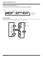
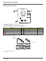
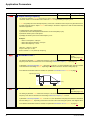
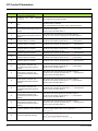
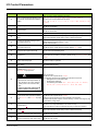
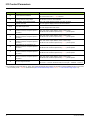
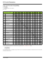
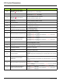
1
2354235 11/2008
Altivar 21
Variable speed drives
for asynchronous motors
Programming Manual
Software V1.9
AAV75193
09/2009
www.schneider-electric.com
Contents
Important information __________________________________________________________________________________________ 5
Before You Begin _____________________________________________________________________________________________ 6
Documentation structure________________________________________________________________________________________ 8
Installation Manual ______________________________________________________________________________________ 8
Programming Manual ____________________________________________________________________________________ 8
Manuals for Modbus, Lonworks, BACnet, Metasys N2, Apogee FLN _______________________________________________ 8
Software enhancements ________________________________________________________________________________________ 9
Enhancements made to version V1.1 in comparison to V1.0 _____________________________________________________ 9
Enhancements made to version V1.2 in comparison to V1.1 _____________________________________________________ 9
Enhancements made to version V1.3 in comparison to V1.2 _____________________________________________________ 9
Enhancements made to version V1.6 in comparison to V1.3 _____________________________________________________ 9
Enhancements made to version V1.7 in comparison to V1.6 _____________________________________________________ 9
Enhancements made to version V1.8 in comparison to V1.7 _____________________________________________________ 9
Enhancements made to version V1.9 in comparison to V1.8 _____________________________________________________ 9
Steps for setting up the drive ___________________________________________________________________________________ 10
Factory configuration _________________________________________________________________________________________ 11
Setup – Preliminary recommendations____________________________________________________________________________ 12
Power switching via line contactor _________________________________________________________________________
User adjustment and extension of functions _________________________________________________________________
Test on a low power motor or without a motor ________________________________________________________________
Using motors in parallel _________________________________________________________________________________
Using in single phase supply _____________________________________________________________________________
12
12
13
13
13
Graphic display terminal _______________________________________________________________________________________ 14
Graphic display terminal features _________________________________________________________________________
Graphic display terminal modes __________________________________________________________________________
Monitoring Mode ______________________________________________________________________________________
Run Mode ___________________________________________________________________________________________
Programming Mode ____________________________________________________________________________________
14
15
15
19
19
Menu Structure ______________________________________________________________________________________________ 20
Menu Navigation_______________________________________________________________________________________ 20
Submenus____________________________________________________________________________________________ 22
Accessing and Changing Parameters ______________________________________________________________________ 22
Common control schemes _____________________________________________________________________________________ 24
2-wire control _________________________________________________________________________________________
3-wire control _________________________________________________________________________________________
External speed control potentiometer ______________________________________________________________________
4-20 mA speed control __________________________________________________________________________________
Preset speeds (up to seven) _____________________________________________________________________________
Serial communication __________________________________________________________________________________
Forced local __________________________________________________________________________________________
PID control ___________________________________________________________________________________________
24
25
26
26
27
28
28
29
Drive Operation______________________________________________________________________________________________ 30
Local and Remote Modes of Operation _____________________________________________________________________
Local Mode __________________________________________________________________________________________
Resetting drive Faults in Local Mode _______________________________________________________________________
Logic Input Functions Active in Local Mode _________________________________________________________________
Remote Mode ________________________________________________________________________________________
30
33
33
34
34
Quick Start _________________________________________________________________________________________________ 37
Quick menu AUF ______________________________________________________________________________________ 37
Motor parameters _____________________________________________________________________________________ 40
Programming Parameters______________________________________________________________________________________ 41
Parameter Reset (tYP) _________________________________________________________________________________
Macro Programming (AU4) ______________________________________________________________________________
Parameter Lock (F700) _________________________________________________________________________________
Display of Submenu AUF (F738) __________________________________________________________________________
AAV75193 09/20009
41
42
43
43
3
Contents
Motor Control Parameters _____________________________________________________________________________________ 44
Motor Control Mode (Pt) ________________________________________________________________________________ 44
Motor Tuning _________________________________________________________________________________________ 48
Auto-tuning __________________________________________________________________________________________ 49
Supply Voltage Correction and Motor Voltage Limitation (F307) __________________________________________________ 51
Motor 2 Control Parameters _____________________________________________________________________________ 52
Drive Control Parameters ______________________________________________________________________________________ 54
Application Parameters________________________________________________________________________________________ 59
Skip Frequencies ______________________________________________________________________________________ 65
DC Injection Braking Parameters _________________________________________________________________________ 66
I/O Control Parameters________________________________________________________________________________________ 67
Logic Input Function Compatibility _________________________________________________________________________ 71
Relay Output Functions _________________________________________________________________________________ 72
Analog Input Functions __________________________________________________________________________________ 78
Analog Output Functions ________________________________________________________________________________ 79
Logic Inputs Function ___________________________________________________________________________________ 80
Analog Input Adjustments (F201–F204; F160-F163; F210–F213; F470–F473)_______________________________________ 81
Always Active Logic Function ____________________________________________________________________________ 89
Preset Speeds (Sr1 – Sr7) _______________________________________________________________________________ 90
+/- Speed Control Parameters ____________________________________________________________________________ 91
Display Parameters __________________________________________________________________________________________ 94
Fault Management Parameters _________________________________________________________________________________ 97
Catch On The Fly (F301) ________________________________________________________________________________ 99
Overtorque Detection __________________________________________________________________________________ 105
Nuisance Overvoltage And Input Phase Fault Avoidance ______________________________________________________ 106
Motor Overload Characteristics (OLN) ____________________________________________________________________ 107
Serial Communication Parameters ______________________________________________________________________________ 109
Start/Stop Control By Speed Reference Level _____________________________________________________________________ 114
Droop Control ______________________________________________________________________________________________ 115
Permanent Magnet Motor _____________________________________________________________________________________ 116
Options ___________________________________________________________________________________________________ 117
Faults - Causes - Remedies ___________________________________________________________________________________ 118
Fault Conditions ______________________________________________________________________________________
Alarm Conditions _____________________________________________________________________________________
Pre-alarm Conditions __________________________________________________________________________________
Resetting the drive after a Fault Condition __________________________________________________________________
118
121
122
122
Parameters reset tables ______________________________________________________________________________________ 123
Parameter Reset _____________________________________________________________________________________
Parameter values that do not vary by reset type _____________________________________________________________
Parameter values that vary according to reset type ___________________________________________________________
Parameter values that vary according to drive model, but not reset type___________________________________________
Parameter values that vary according to drive model and reset type______________________________________________
Parameter values that do not change if reset ________________________________________________________________
123
123
128
128
130
131
User settings tables _________________________________________________________________________________________ 132
4
AAV75193 09/20009
Important information
PLEASE NOTE
Please read these instructions carefully and examine the equipment in order to familiarize yourself with the device before installing,
operating or carrying out any maintenance work on it.
The following special messages that you will come across in this document or on the device are designed to warn you about potential risks
or draw your attention to information that will clarify or simplify a procedure.
The addition of this symbol to a “Danger” or “Warning” safety label indicates that there is an electrical risk that will result
in injury if the instructions are not followed.
This is a safety warning symbol. It warns you of the potential risk of injury. You must comply with all safety messages that
follow this symbol in order to avoid the risk of injury or death.
DANGER
DANGER indicates an imminently hazardous situation which, if not avoided, will result in death, serious injury or equipment
damage.
WARNING
WARNING indicates a potentially hazardous situation which, if not avoided, can result in death, serious injury or equipment damage.
CAUTION
CAUTION indicates a potentially hazardous situation which, if not avoided, can result in injury or equipment damage.
PLEASE NOTE:
Only qualified personnel are authorized to carry out maintenance work on electrical equipment. Schneider Electric accepts no responsibility
for the consequences of using this device. This document does not constitute an instruction manual for inexperienced personnel.
© 2008 Schneider Electric. All rights reserved.
AAV75193 09/20009
5
Before You Begin
Read and understand these instructions before performing any procedure with this drive.
DANGER
HAZARD OF ELECTRIC SHOCK, EXPLOSION, OR ARC FLASH
• Read and understand this manual before installing or operating the Altivar 21 drive. Installation, adjustment, repair, and
maintenance must be performed by qualified personnel.
• The user is responsible for compliance with all international and national electrical code requirements with respect to
grounding of all equipment.
• Many parts of this drive, including the printed circuit boards, operate at the line voltage. DO NOT TOUCH. Use only
electrically insulated tools.
• DO NOT touch unshielded components or terminal strip screw connections with voltage present.
• DO NOT short across terminals PA/+ and PC/– or across the DC bus capacitors.
• Before servicing the drive:
— Disconnect all power.
— Place a “DO NOT TURN ON” label on all power disconnects.
— Lock all power disconnects in the open position.
— Disconnect all power, including external control power that may be present, before servicing the drive. WAIT
15 MINUTES to allow the DC bus capacitors to discharge. Then follow the “Bus Voltage Measurement Procedure”
located in the Installation Manual, to verify that the DC voltage is less than 42 V. The drive LED is not an indicator of the
absence of DC bus voltage.
• Install and close all covers before applying power or starting and stopping the drive.
Failure to follow these instructions will result in death or serious injury.
DANGER
UNINTENDED EQUIPMENT OPERATION
Before turning on the drive or upon exiting the configuration menus, ensure that the inputs assigned to the Run command
are in a state that will not cause the drive to run. Otherwise, the motor can start immediately.
Failure to follow this instruction will result in death, serious injury, or equipment damage.
DANGER
UNINTENDED EQUIPMENT OPERATION
• Prevent accidental grounding of logic inputs configured for sink logic. Accidental grounding can result in unintended
activation of drive functions.
• Protect the signal conductors against damage that could result in unintentional conductor grounding.
Failure to follow these instructions will result in death or serious injury.
6
AAV75193 09/20009
Before You Begin
WARNING
LOSS OF CONTROL
• The designer of any control scheme must consider the potential failure modes of control paths and, for certain critical
control functions, provide a means to achieve a safe state during and after a path failure. Examples of critical control
functions are emergency stop and overtravel stop.
• Separate or redundant control paths must be provided for critical control functions.
• System control paths may include communication links. Consideration must be given to the implications of unanticipated
transmission delays or failures.
• Each implementation of an Altivar 21 drive must be individually and thoroughly tested for proper operation before being
placed into service.
Failure to follow these instructions can result in death, serious injury, or equipment damage.
WARNING
LOSS OF CONTROL
• Set the communication error trip time to stop the drive in case the remote graphic display terminal display is deactivated
by an unusual event such as tripping, an operation error, or a power outage.
• Ensure that the communication error trip time is properly set before deactivating the remote graphic display terminal
display.
Failure to follow these instructions can result in death, serious injury, or equipment damage.
AAV75193 09/20009
7
Documentation structure
The following Altivar 21 technical documents are available on the Telemecanique website (www.telemecanique.com) as well as on the
CD-ROM supplied with the drive.
Installation Manual
This manual contains complete mounting and wiring instructions.
Programming Manual
This describes the functions, parameters and use of the drive terminal (integrated display terminal and graphic display terminal).
The communication functions are not described in this manual, but in the manual for the bus or network used.
Manuals for Modbus, Lonworks, BACnet, Metasys N2, Apogee FLN
These manuals describe the assembly, connection to the bus or network, signaling, diagnostics, and configuration of the
communication-specific parameters via the integrated display terminal or the graphic display terminal.
They also describe the communication services of the protocols.
8
AAV75193 09/20009
Software enhancements
Since the Altivar ATV21 was first launched, it has benefited from the addition of several new functions. The software version is now V1.9.
The old versions can be replaced by this new one without any modifications.
Although this documentation relates to version V1.9, it can still be used with earlier versions, as the updates merely involve the addition of
new values and parameters, and none of the parameters of the previous versions have been modified or removed.
The software version is indicated on the nameplate attached to the body of the drive.
Enhancements made to version V1.1 in comparison to V1.0
• New factory value for Supply Voltage Correction and Motor Voltage Limitation F307 =
Supply Voltage Corrected - motor voltage unlimited (F307 = 3). See page 51.
• Modify factory value for Motor No-load Current F416 = According to drive model. See page 48.
• New factory value for FL Relay Function F132 = Inversion of fault relay (F132 = 11). See page 85.
• No detection of Ground Fault EF2 during Line supply undervoltage fault MOFF over 22 kW product.
Enhancements made to version V1.2 in comparison to V1.1
• New factory value for Motor Current Limit F601 = 110 % of the drive’s output current rating. See page 47.
• New factory value for Motor 2 Current Limit F185 = 110 % of the drive’s output current rating. See page 52.
• In case of Supply Voltage Correction and Motor Voltage Limitation F307 = Supply voltage uncorrected (F307 = 0 or 2),
auto-swap the Motor rated voltage ulu as 200 V (200 V range) or 400 V (400 V range). See page 51 and page 40.
Enhancements made to version V1.3 in comparison to V1.2
• New factory value for Time-out F803 = 3 seconds of the drive’s output current rating. See page 110.
Enhancements made to version V1.6 in comparison to V1.3
•
•
•
•
•
•
New factory value for Auto Fault Reset F303 = Disabled (F303 = 0). See page 97.
Overvoltage Fault OPx is automatically re-start when Auto Fault Reset F303 = Disabled (F303 = 0). See page 120and page 97.
New factory value for Disabling of graphic display terminal Fault Reset Function F735 = Disabled (F735 = 1). See page 58.
Improvement of speed search function.
Modify external keypad interface (text on "Stop" button becomes "Stop / Reset").
Stop key from optional graphic display terminal (VW3A21101).
Enhancements made to version V1.7 in comparison to V1.6
• New parameter Power supply adjustment gain F484. See page 106.
• Clear PID integral value (function 65) and PID Control Prohibited (function 14) are valid for all
Remote Mode Start/Stop Control CMOd adjustment.
Enhancements made to version V1.8 in comparison to V1.7
• Improvement countermesure of vibration issue (F484). See page 106.
Enhancements made to version V1.9 in comparison to V1.8
New parameters:
• Delay for RY-RC Relay F146. See page 85.
• Delay for FL Relay F147. See page 85.
• Threshold logic for relay link to VIA F160. See page 81.
• Hysteresis threshold for logic relay link to VIA F161. See page 81.
• Threshold logic for relay link to VIB F162. See page 81.
• Hysteresis threshold for logic relay link to VIB F163. See page 81.
• PI regulator reversal direction correction F380. See page 87.
• Stop on LL hysteresis F391. See page 87.
• PI wake up threshold on PI error F392. See page 87.
• PI wake up threshold on PI feedback error F393. See page 87.
• Drive behaviour on 4-20 event F644. See page 104.
• Fallback speed F649. See page 104.
• Low frequency when analog output equal 0 V F694. See page 84.
• High frequency when analog output equal 0 V F695. See page 84.
AAV75193 09/20009
9
Steps for setting up the drive
INSTALLATION
v 1 Consult the Installation Manual
PROGRAMMING
b 2 Configure the parameters
v Quick menu AUF
v Motor parameters
v Perform an auto-tuning operation
Tips:
b 3 Start
• Before you start programming,
complete the user setting tables, page
132.
• Perform an auto-tuning operation to
optimize performance, page 48.
• If you get lost, return to the factory
settings, page 123.
Note: Check that the wiring
of the drive is compatible with
its configuration.
10
AAV75193 09/20009
Factory configuration
Drive factory settings
The Altivar 21 is factory-set for the most common operating conditions:
•
•
•
•
•
Motor Control Mode Pt : Variable torque (Pt = 1). See page 45.
High speed UL = 50.0 Hz. See page 59.
Low speed LL = 0.0 Hz. See page 59.
Switching Frequency Level F300: depending on drive rating (see page 64)
Auto Ramp Adaptation AU1 = Enabled (AU1 = 1). See page 64.
Parameter which depends on Macro Programming AU4 = Factory setting 0 (see page 42):
• Command reference: logic inputs (CNOd = 0). See Remote Mode Start/Stop Control page 54.
• Speed reference: analog input VIA = 0–10 V or 0–20 mA (FNOd = 1, F201 = 0). See Remote Mode Primary Speed Reference
Source FMOD page 54 and Analog Input Speed Reference page 81.
• F: run forward (F111 = 2). See F Logic Input Function page 80.
• R: preset speed 1 (F112 = 6). See R Logic Input Function page 80.
• RES: fault reset (F113 = 10). See RES Logic Input Function page 80.
• Drive ready for operation (F110 = 1). See Always Active Logic Function 2 page 89.
If the above values are compatible with the application, the drive can be used without changing the settings.
AAV75193 09/20009
11
Setup – Preliminary recommendations
CAUTION
INCOMPATIBLE LINE VOLTAGE
Before turning on and configuring the drive, ensure that the line voltage is compatible with the supply voltage range shown on the drive
nameplate. The drive may be damaged if the line voltage is not compatible.
Failure to follow these instructions can result in equipment damage.
Power switching via line contactor
CAUTION
UNINTENDED EQUIPMENT OPERATION
• Avoid operating the contactor frequently (premature ageing of the filter capacitors).
• Cycle times < 60 s may result in damage to the pre-charge resistor.
Failure to follow these instructions can result in equipment damage.
User adjustment and extension of functions
• The display unit and buttons can be used to modify the settings and to extend the functions described in the following pages.
• Return to factory settings is made easy by the Parameter Reset tYP (see page 41).
DANGER
UNINTENDED EQUIPMENT OPERATION
• Check that changes made to the settings during operation do not present any danger.
• We recommend stopping the drive before making any changes.
Failure to follow these instructions will result in death or serious injury.
12
AAV75193 09/20009
Setup – Preliminary recommendations
Test on a low power motor or without a motor
• In factory settings mode, Output Phase Failure Detection Mode F605 (see page 102) is active (F605 = 3). To check the drive
in a test or maintenance environment without having to switch to a motor with the same rating as the drive (particularly useful in the
case of high power drives), deactivate F605 = 0.
• Set Motor Control Mode Pt = Constant V/Hz 0 (see page 45)
CAUTION
UNINTENDED EQUIPMENT OPERATION
Motor thermal protection will not be provided by the drive if the motor current is less than 0.2 times the rated drive current. Provide an
alternative means of thermal protection.
Failure to follow these instructions can result in equipment damage.
Using motors in parallel
• Set Motor Control Mode Pt = Constant V/Hz 0 (see page 45).
CAUTION
UNINTENDED EQUIPMENT OPERATION
Motor thermal protection is no longer provided by the drive. Provide an alternative means of thermal protection on every motor.
Failure to follow these instructions can result in equipment damage.
Using in single phase supply
• Set Input Phase Failure Detection Mode F608 = Disabled 0 (see page 100).
CAUTION
UNINTENDED EQUIPMENT OPERATION
Using ATV21 in single phase supply is only allowed in training mode with motor and without load.
Failure to follow these instructions can result in equipment damage.
AAV75193 09/20009
13
Graphic display terminal
This section describes the features of the integrated graphic display terminal display. An optional graphic display terminal (VW3A21101) is
also available.
Graphic display terminal features
1
4
2
5
RUN
3
%
PRG
Hz
MON
Loc
Rem
MODE
8
ENT
9
6
7
10
RUN
LED/Key
11
13
14
Characteristics
1
Display RUN LED
• Illuminates when a run command is applied to the drive.
• Flashes when there is a speed reference present with a Run command.
2
Display PRG LED
• Illuminates when Programming mode is active.
• Flashes in AUF, GrU modes
3
Display MON LED
• Illuminates when Monitoring mode is active.
• Flashes in fault history display mode
4
Display unit
5
Display unit LED
• The % LED illuminates when a displayed numeric value is a percentage.
• The Hz LED illuminates when a displayed numeric value is in hertz.
6
UP/DOWN keys
Depending on the mode, you can use the arrows to:
• Navigate between the menus
• Change a value
• Change the speed reference when the UP/DOWN LED (7) is illuminated
7
UP/DOWN LED
Illuminates when the navigation arrows are controlling the speed reference
8
Loc/Rem LED
4 digits, 7 segments
Illuminates when Local mode is selected
Press to select the graphic display terminal mode.
• Run mode (default on power-up)
• Programming mode
• Monitoring mode
Can also be used to go back to the previous menu.
9
MODE
10
Loc/Rem
11
ENT
12
RUN LED
13
RUN
Pressing this key when the RUN LED is illuminated starts the drive.
STOP
Stop/reset key.
In Local mode, pressing the STOP key causes the drive to stop based on the setting of parameter
F721.
In Remote mode, pressing the STOP key causes the drive to stop based on the setting of parameter
F603. The display will indicate a flashing “E”.
If F735 is set to 0 (default setting), pressing the stop key twice will reset all resettable faults if the fault
condition has been resolved.
14
14
STOP
12
Switches between Local and Remote modes
Press to display a parameter’s value or to save a changed value.
Illuminates when the Run key is enabled
AAV75193 09/20009
Graphic display terminal
Graphic display terminal modes
The Altivar 21 graphic display terminal has three modes of operation: Monitoring, Run and Programming.
The drive powers up in the Run mode. To select a different mode, use the MODE key as illustrated below.
ATV21 drive
Power Up
Run
mode
RUN
MODE
0.0
PROG
Programming
mode
Monitoring
mode
MODE
AUF
MODE
Fr-F
MON
Hz
MODE
MODE Key
Monitoring Mode
The Monitoring mode displays drive operational data in real time. To access the Monitoring mode, press the MODE key until the MON LED
is illuminated. Then use the UP and DOWN keys to view up to 30 different types of data.
MODE Mode key
C80
PROG
AUF
Up/Down keys
F60.0
MODE
MON
Fr-F
MODE
RUN
MODE
AAV75193 09/20009
t0.10
25 other
parameters
0.0
n---
15
Graphic display terminal
Monitoring Mode Displays
Display
Fr-F
Name
Description
Direction of rotation Fr-F = forward direction
Fr-r = reverse direction
F 60.0 Speed reference
Command frequency to drive, displayed either as Hz or in custom unit set by parameter F702
C 80
Motor current
The average of the 3 phases of motor current displayed either as amperes or as a percentage of the
drive's nameplate-rated output current. Select % or A with parameter F701.
Y 100
Line voltage
The average of the 3 phases of line to line input voltages displayed either in volts or as a percentage
of the drive's rated input voltage (200 V for 208/240 V models - 400 V for 480 V models). Select % or
volts with parameter F701.
P 100
Motor voltage
The average of the 3 phases of line to line output voltages displayed either in volts or as a percentage
of the drive's rated output voltage (200 V for 208/240 V models - 400 V for 480 V models). Select %
or volts with parameter F701.
q 60
Motor torque
Estimated motor torque as a percentage of the motor's rated torque
c 90
Torque current
The average of the 3 phases of torque-producing motor current displayed either as amperes or as a
percentage of the motor's rated torque-producing current. Select % or A with parameter F701.
L 70
drive load factor
The motor current as a percentage of the drive's rated output current, which may be reduced from the
drive’s nameplate current rating by adjustments in switching frequency.
h 80
Input power
drive input power displayed in kilowatts (kW)
H 75
Output power
drive output power displayed in kilowatts (kW)
o 60.0 Motor operating
frequency
. .11
Logic input map
Motor operating frequency, displayed either as Hz or in custom unit set by parameter F702
The bar representing VIA is displayed only if F109 = 1 or 2
ON:
OFF:
F
VIA
R
RES
0.1
Relay output map
ON:
OFF:
FL
RY-RC
u 101
CPU 1 version
Version of CPU 1
u c01
CPU 2 version
Version of CPU 2
uE01
Memory version
Version of memory
d 50
PID feedback
Level of PID feedback, displayed either as Hz or in custom unit set by parameter F702
b 70
PID computed
speed reference
Speed reference command to drive as computed by the PID function, displayed either as Hz or in
custom unit set by parameter F702
h 85
Accumulated input
power
consumption
Accumulated input power consumed by the drive displayed in kWh
H 75
Accumulated
output power
consumption
Accumulated output power supplied by the drive displayed in kWh
A 16.5 Drive rated output
current
1500
16
Motor speed
Drive nameplate rated output current in amperes
Motor speed in rpm
AAV75193 09/20009
Graphic display terminal
Monitoring Mode Displays (continued)
Display
Name
Description
N 50
Communication
counter
Displays the counter numbers of communication through the network
n 50
Normal state
Displays the counter numbers of communication only at normal state in all communication through the
network
OC3⇔1
Past fault 1
The most recent fault stored in the fault history. If the drive is in a fault state, this is not the active fault.
A fault is stored in the fault history after it is cleared by fault reset action. Press ENT to review drive
state at time of fault. See “Fault Display and History” on page 18 and “Faults - Causes - Remedies” on
page 118 for more detail.
OH⇔2
Past fault 2
Second most recent fault.
OP3⇔3
Past fault 3
Third most recent fault.
nErr⇔
4
Past fault 4
N ...1 Drive service alarm
Fourth most recent fault.
ON:
OFF:
Cumulative
Operation
Time
t0.10
Drive run time
AAV75193 09/20009
Cooling fan
Main Control board
DC Bus capacitor
Cumulative drive run time. 0.01 = 1 hour.
1.00 = 100 hours
17
Graphic display terminal
Fault Display and History
When the drive faults, the graphic terminal displays a fault code. To review data about drive operation at the time of the fault, press the
MODE key to enter the Monitoring mode. Then use the Up/Down keys to scroll through the data listed in table page 16.
Up to five faults can be displayed on the graphic terminal in Monitoring mode: the present fault (if the drive is in a fault state) and the previous
four faults. To review drive operation data recorded at the time of fault for a previous fault, press ENT when the code for the fault is displayed.
See table below for the available information.
When a fault is reset or power is cycled to the drive, the present fault becomes Past Fault 1.
Fault History
Display
Name
Description
Fault counter
n 2
Number of times in succession that this particular fault has occurred
o 60.0 Motor operating
frequency
Motor operating frequency, displayed either as Hz or in custom unit set by parameter F702
Fr-F = forward direction
Fr-r = reverse direction
Direction of
rotation
Fr-F
F 60.0 Speed reference
Command frequency to drive, displayed either as Hz or in custom unit set by parameter F702
C 80
Motor current
The average of the 3 phases of motor current displayed either as A or as a percentage of the drive's
nameplate-rated output current. Select % or A with parameter F701.
Line voltage
The average of the 3 phases of line to line input voltages displayed either in volts or as a percentage of
the drive's rated input voltage (200 V for 208/240 V models - 400 V for 480V models). Select % or volts
with parameter F701.
Motor voltage
The average of the 3 phases of line to line output voltages displayed either in volts or as a percentage
of the drive's rated output voltage (200 V for 208/240 V models - 400 V for 480 V models). Select % or
volts with parameter F701.
Y 100
P 100
. .11
The bar representing VIA is displayed only if
F109 = 1 or 2
ON:
OFF:
Logic input map
F
VIA
R
RES
ON:
OFF:
0.1
Relay output map
FL
t0.10
Drive run time
RY-RC
Cumulative drive run time. 0.01 = 1 hour. 1.00 = 100 hours
I/O Map
In both the monitoring mode and the fault history, it is possible to view the state of the logic inputs and the relay outputs. See previous tables
on pages 16 and 18.
Logic Input Map
ON:
OFF:
F
VIA
R
RES
The ON or OFF status of each logic input is displayed in bits. VIA is included in this display if parameter F109 is set to either 1 or 2.
Relay Output Map
ON:
OFF:
FL
RY-RC
The ON or OFF status of each relay output is displayed in bits.
18
AAV75193 09/20009
Graphic display terminal
Run Mode
To access the Run mode, press the MODE key until the drive operating frequency, a fault code, or a pre-alarm code is displayed.
See Faults - Causes - Remedies beginning on page 118 for the fault and pre-alarm codes.
Changing the Display in Run Mode
Motor operating frequency is the default value displayed on the graphic terminal in Run mode. This displayed value can be changed by
setting parameter Default graphic display terminal Operational Value F710. See page 94 for a list of the display choices.
The displayed value can be expressed as a percentage of the drive rating, or in amperes or volts, as appropriate for the value displayed.
The units can be changed by setting parameter Graphic display terminal (% or A/V Units) F701 (see page 94).
In addition, the resolution of the speed reference and output frequency displays can be adjusted by setting parameters Local Mode Speed
Reference Step Changes F707 and Graphic display terminal Frequency Resolution F708 (see pages 55 and 94).
Programming Mode
Use this mode to program the drive.
To access the Programming mode, use the MODE key until the PRG indicator LED on the display is illuminated.
AAV75193 09/20009
19
Menu Structure
Menu Navigation
Menu navigation diagrams below and page 21 illustrate how to navigate through the programming menus and submenus.
RUN
Power
Up
0.0
Hz
Mode
Mode
ENT
a
AUH
Mode
To Bottom
of List
ENT
MON
Fr - F
PRG
b
AUF
Mode
Monitoring
Mode
Mode
Programming
Mode
ENT
c
GrU
Mode
ENT
d
F-- -- -Mode
Sr 1...7
OLN
Mode Mode Key
ENT
tHr
ub
ENT Key
Pt
UP/DOWN Key
Refer to diagram on
next page for:
a Last Five Used Parameters
uLu
uL
LL
b
Frequently Used Parameters
c
Changes From Factory Setting
d
Additional Parameters
UL
FH
dEC
ACC
Fr
tyP
Fn
FnSL
FnOP
CnoD
AU4
To Top
of List
AU1
20
AAV75193 09/20009
Menu Structure
Menu Navigation (continued)
a
History parameters
User parameters
c
1. Pressing the UP key
searches the
parameter list
starting with the first
one changed.
OLN
ENT
*
AUH
Mode
U -- -- F
4
*
3
*
1
*
U -- -- F
3
*
1
U -- -- F
ENT
LL
U -- -- --
GrU
Mode
2
U -- -- r
3
b
Quick menu
2
HEAD
3. The number of
parameters
displayed within the
GrU menu
depends upon how
many have been
altered from their
factory settings.
4. When all the
changed parameters
have been displayed,
the display returns to
GrU.
3
ENT
AU1
AUF
U -- -- r
2. Pressing the DOWN
key searches the
parameter list
starting with the last
one changed.
2
U -- -- r
Mode
ACC
dEC
LL
d
Extended parameters
UL
*
tHr
To Bottom
of List
F102
Fn
F101
ENT
Pt
F100
F-- -- -uL
Mode
F912
uLu
F911
To Top
of List
END
*
AAV75193 09/20009
21
Menu Structure
Submenus
The ATV21 drive features 4 submenus (see diagram on page 21) that are designed to reduce the time and effort required to program
application parameters. Parameters can be modified within these submenus.
AUH: History Parameters
The AUH submenu displays, in reverse chronological order, the last 5 parameters that have been changed from their factory settings. Each
time the AUH submenu is accessed, it searches for the latest parameters changed from their factory settings. If all parameters are at their
factory settings, no display is generated.
Parameter Lock F700 is not displayed in the AUH menu, even if its value has been changed (see page 43).
AUF: Quick Menu
The AUF submenu provides ready access to the ten basic parameters commonly used in programming the drive. In many cases,
programming the ATV21 drive is complete when these 10 parameters have been properly set (see chapter Quick Menu page 37).
GrU: User Parameters
The GrU submenu displays all parameters that have been changed from their factory settings. Each time the GrU submenu is accessed,
its content is refreshed with the latest list of parameters changed from their factory settings. If all parameters are at their factory setting, no
display is generated.
Parameters Fn and F470 – F473 are not displayed in the GrU menu, even if their values have been changed.
F– – –: Extended Parameters
The extended parameter submenu provides access to parameters used for special settings and applications.
Accessing and Changing Parameters
The diagram below illustrates how to access and change parameter values.
ENT
1
AUF
AU1
ENT
10.0
ACC
ENT
3.0
2
Save Change
Discard
Changes
22
Mode
AAV75193 09/20009
Menu Structure
Parameters that cannot be changed while the drive is running
The table below lists the parameters that cannot be changed unless the drive is stopped (displaying 0.0 or OFF on the graphic display
terminal).
Parameter Description
Parameter Description
AU1
Auto ramp adaptation
F316
Switching frequency control mode
AU4
Macro programming
F400
Auto tuning enable
CNOd
Remote mode start/stop control source
F415
Motor rated full load current
FNOd
Remote mode primary speed reference source
F416
Motor no-load current
tYp
Parameter reset
F417
Motor rated speed
FH
Maximum frequency
F418
Frequency loop gain
uL
Motor rated frequency
F419
Frequency loop stability
uLu
Motor rated voltage
F480
Magnetizing current coefficient
Pt
Motor control mode
F481
Line noise compensation filter
F108
Always active logic function 1
F482
Line noise inhibitor filter
F109
VIA input function (analog or logic selection)
F483
Line noise inhibitor gain
F110
Always active logic function 2
F484
Power supply adjustment gain
F111
F logic input function
F485
Stall prevention control coefficient 1
F112
R logic input function
F492
Stall prevention control coefficient 2
F113
RES logic input function
F494
Motor adjustment coefficient
F118
VIA logic input function
F495
Maximum voltage adjustment coefficient
F130
RY-RC relay primary function
F496
Waveform switching adjustment coefficient
F132
FL relay function
F601
Motor current limit
F137
RY-RC relay secondary function
F603
External fault stop mode
F139
RY-RC relay function logic selection
F605
Output phase failure detection mode
F170
Motor 2 rated frequency
F608
Input phase failure detection mode
F171
Motor 2 rated voltage
F613
Output short-circuit detection mode
F300
Switching frequency level
F626
Overvoltage fault operation level
F301
Catch on the fly
F627
Undervoltage fault operation mode
F303
Auto fault reset
F732
Disabling of graphic display terminal local/remote
key
F302
Coast to stop on loss of input power
F910
Permanent magnet motor step-out detection current
level
F305
Overvoltage fault protection
F911
Permanent magnet motor step-out detection time
F307
Supply voltage correction and motor voltage
limitation
F912
Permanent magnet motor high-speed torque
adjustment coefficient
F311
Motor rotation direction command
AAV75193 09/20009
23
Common control schemes
2-wire control
PO
R/L1
S/L2
T/L3
PA/+
PC/-
RUN
%
PRG
M
Hz
MON
Loc
Rem
FLC
FLB
MODE
F
Run forward
ENT
R
Run reverse
RES
FLA
RY
RC
U/T1
V/T2
W/T3
RUN
STOP
FM
CC
SW4
SOURCE
P24
PLC
PLC
FM
SINK
VIA
V
V
I
I
PP VIA VIB CC
1.
2.
3.
4.
Wire the logic inputs as indicated in the above figure.
Set switch SW4 to source.
Program common parameters of ATV21 (see Quick Start page 37).
Program specific parameters for 2-wire control as indicated in the following table:
Parameter
Page
Setting
Factory value
CNOd (remote mode start/stop control)
54
0 (control terminal logic inputs)
F111 (F logic input function)
80
2 (forward run command)
2
F112 (R logic input function)
80
3 (reverse run command)
6
0
Note: F111 and F112 must not be switched simultaneously or the drive will go at 0 speed.
24
AAV75193 09/20009
Common control schemes
3-wire control
PO
R/L1
S/L2
T/L3
PA/+
PC/-
RUN
%
PRG
M
Hz
MON
Loc
Rem
FLC
FLB
MODE
F
ENT
R
Start forward
RES
FLA
RY
RC
U/T1
V/T2
W/T3
RUN
Stop
STOP
FM
Start reverse
CC
SW4
SOURCE
P24
PLC
PLC
FM
SINK
VIA
V
V
I
I
PP VIA VIB CC
1.
2.
3.
4.
Wire the logic inputs as indicated in the above figure.
Set switch SW4 to source.
Program common parameters of ATV21 (see Quick Start page 37).
Program specific parameters for 3-wire control as indicated in the following table:
Parameter
Page
Setting
Factory value
CNOd (remote mode start/stop control)
54
0 (control terminal logic inputs)
0
F111 (F logic input function)
80
2 (start forward - 3 wire control)
2
F112 (R logic input function)
80
49 (stop input - 3 wire control)
6
F113 (RES logic input function)
80
3 (start reverse - 3 wire control)
10
3 wire control timing diagram:
Output frequency
Forward run
0
Reverse run
R - Stop
F - Forward start
RES - Reverse start
ON
OFF
ON
OFF
ON
OFF
ON
Line power
AAV75193 09/20009
OFF
25
Common control schemes
External speed control potentiometer
PO
R/L1
S/L2
T/L3
PA/+
PC/-
RUN
%
PRG
M
Hz
MON
Loc
Rem
FLC
FLB
MODE
F
ENT
R
RES
FLA
RY
RC
U/T1
V/T2
W/T3
RUN
STOP
FM
CC
SW4
SOURCE
P24
PLC
PLC
FM
SINK
VIA
V
V
I
I
SW3
PP VIA VIB CC
2.2 to 10 kOhm - 1/4 Watt
1.
2.
3.
4.
Wire the analog input as indicated in the above figure.
Set switch SW3 to V (voltage).
Program common parameters of ATV21 (see Quick Start page 37).
Program specific parameters for external speed control potentiometer as indicated in the following table:
Parameter
Page
Setting
Factory value
FNOd (remote mode primary speed reference source)
54
1 (VIA)
1
F109 (VIA input function - analog or logic selection)
80
0 (Analog input)
0
F200 (auto/manual speed reference switching)
83
0 (Enabled)
0
4-20 mA speed control
PO
R/L1
S/L2
T/L3
PA/+
PC/-
RUN
%
PRG
M
Hz
MON
Loc
Rem
FLC
FLB
MODE
F
ENT
R
RES
FLA
RY
RC
U/T1
V/T2
W/T3
RUN
STOP
FM
CC
SW4
SOURCE
P24
PLC
PLC
FM
SINK
VIA
V
V
I
I
SW3
PP VIA VIB CC
4-20 mA Current signal
1.
2.
3.
4.
Wire the analog input as indicated in the above figure.
Set switch SW3 to I (current).
Program common parameters of ATV21 (see Quick Start page 37).
Program specific parameters for 4-20 mA speed control as indicated in the following table:
Parameter
Page
Setting
Factory value
FNOd (remote mode primary speed reference source)
54
1 (VIA)
1
F109 (VIA input function - analog or logic selection)
80
0 (Analog input)
0
F200 (auto/manual speed reference switching)
83
0 (Enabled)
0
F201 (VIA speed reference level 1)
81
20 %
0%
26
AAV75193 09/20009
Common control schemes
Preset speeds (up to seven)
PO
R/L1
S/L2
T/L3
PA/+
PC/-
RUN
%
PRG
M
Hz
MON
Loc
Rem
FLC
FLB
MODE
F
ENT
R
RES
FLA
RY
RC
U/T1
V/T2
W/T3
RUN
STOP
FM
CC
SW4
SOURCE
P24
PLC
PLC
FM
SINK
VIA
V
V
I
I
PP VIA VIB CC
1.
2.
3.
4.
Wire the logic and analog inputs as indicated in the above figure.
Set switch SW4 to source.
Program common parameters of ATV21 (see Quick Start page 37).
Program specific parameters for preset speed as indicated in the following table:
Parameter
Page
Setting
Factory value
F109 (VIA input function - analog or logic selection)
80
2 (logic input - source)
0
F111 (F logic input function)
80
2 (forward run command)
2
F112 (R logic input function)
80
6 (preset speed command input 1)
6
F113 (RES logic input function)
80
7 (preset speed command input 2)
10
F118 (VIA logic input function)
80
8 (preset speed command input 3)
7
Example of 7-step preset speed operation:
Output
frequency
(Hz)
Time (sec)
0
F
ON
OFF
R
ON
OFF
RES
VIA
ON
OFF
ON
OFF
See page 90 for additionnal information.
AAV75193 09/20009
27
Common control schemes
Serial communication
PO
R/L1
S/L2
T/L3
PA/+
PC/-
RUN
%
PRG
M
Hz
MON
Loc
Rem
FLC
F
MODE
R
ENT
FLB
RES
FLA
RY
RC
U/T1
V/T2
W/T3
RUN
STOP
FM
CC
SW4
SOURCE
P24
PLC
PLC
FM
SINK
VIA
V
V
I
I
PP VIA VIB CC
1. For Modbus serial communication, plug the network cable into RJ45 connector on the main control board.
2. Program common parameters of ATV21 (see Quick Start page 37).
3. Program specific parameters for serial communication as indicated in the following table:
Parameter
Page
Setting
Factory value
CNOd (remote mode start/stop control)
54
2 (serial communication)
0
FNOd (remote mode primary speed reference source)
54
4 (serial communication)
1
Forced local
PO
R/L1
S/L2
T/L3
PA/+
PC/-
RUN
%
PRG
M
Hz
MON
Loc
Rem
FLC
FLB
MODE
F
ENT
R
RES
FLA
RY
RC
U/T1
V/T2
W/T3
RUN
STOP
FM
CC
SW4
SOURCE
Forced
local
P24
PLC
PLC
FM
SINK
VIA
V
V
I
I
PP VIA VIB CC
1.
2.
3.
4.
Wire the logic input as indicated in the above figure.
Set switch SW4 to source.
Program common parameters of ATV21 (see Quick Start page 37).
Program specific parameter for forced local as indicated in the following table:
Parameter
F113 (RES logic input function)
28
Page
80
Setting
48 (forced local)
Factory value
10
AAV75193 09/20009
Common control schemes
PID control
PO
R/L1
S/L2
T/L3
PA/+
PC/-
RUN
%
PRG
M
Hz
MON
Loc
Rem
FLC
FLB
MODE
F
ENT
R
P
RES
FLA
RY
RC
U/T1
V/T2
W/T3
RUN
Feedback
transmitter
STOP
FM
CC
SW4
SOURCE
P24
PLC
PLC
FM
SINK
V
VIA
V
I
I
SW3
PP VIB CC VIA
Setpoint 0 - 10 V
Feedback mA or voltage signal
1. Wire analog inputs as indicated in the above figure.
2. Set switch SW4 to source.
3. If the feedback is a milliamp signal, set switch SW3 to the I (current) position. If the feedback is a voltage signal, set switch SW3 to the
V (voltage) position.
4. Program common parameters of ATV21 (see Quick Start page 37).
5. Program specific parameters for PID control as indicated in the following table:
Parameter
Page
Setting
Factory value
FNOd (remote mode primary speed reference source)
54
2 (VIB)
1
F109 (VIA input function - analog or logic selection)
80
0 (Analog input)
0
F200 (auto/manual speed reference switching)
83
0 (Enabled)
0
F360 (PID control enable)
86
1 (Enabled - feedback source is VIA)
0
F359 (PID control waiting time)
87
0s
F362 (PID proportionnal gain)
86
0.30 %
F363 (PID integral gain)
86
0.20
F366 (PID derivative gain)
87
F380 (PI regulator reversal direction correction)
87
F391 (Stop on LL hysteresis)
87
0.2 Hz
F392 (PI wake up threshold on PI error)
87
0.0 Hz
F393 (PI wake up threshold on PI feedback error)
87
0.0 Hz
AAV75193 09/20009
In accordance with the application
0.00
0
29
Drive Operation
Local and Remote Modes of Operation
Overview
The ATV21 drive has two modes of operation, local and remote.
In local mode, the ATV21 drive can be operated only from the graphic display terminal:
• Use the RUN and STOP keys for command control
• Use the UP and DOWN keys for speed control
In remote mode, the ATV21 drive is operated from a combination of the command and speed reference sources defined by programming
parameters Remote Mode Primary Speed Reference Source FNOd and Remote Mode Start/Stop Control CNOd (see page 54).
Command Sources
The command source (CNOd) choices are:
• External signals to the control terminal logic inputs F, R, RES and VIA
• Serial communication control (Modbus®, Metasys® N2, Apogee® FLN, BACnet, or LonWorks®)
• Graphic display terminal RUN and STOP keys
Speed Reference Sources
The speed reference source (FNOd) choices are:
•
•
•
•
•
•
External signals to the control terminal analog inputs VIA or VIB
(4–20 mA, 0–10 Vdc),
External signals to the control terminal logic inputs assigned to
+/- Speed
Serial communication control (Modbus®, Metasys® N2, Apogee® FLN, BACnet, or LonWorks®)
graphic display terminal UP and DOWN keys
Changes to parameters FNOd and CNOd can only be made when the drive is stopped.
30
AAV75193 09/20009
Drive Operation
Command Mode Selection and Priorities
The diagram below illustrates the control inputs and selection logic which determine the source of the drive's start/stop and speed reference
commands.
Command and Reference Switching
LOC
REM
Commands
CNOd
Logic input
function = 48
Logic inputs
Graphic display
terminal
local/remote key
Graphic display terminal
Serial communication
Serial communication
graphic
display
terminal
Logic input function = 38
or
Parameter F200 = 1
VIA
Run/forward
Run/reverse
References
FNOd
VIB
Graphic
display
terminal
Serial
communication
F207
Serial communication
Speed reference
Graphic
display
terminal
+/- Speed
VIA
VIB
Graphic
display
terminal
Serial communication
+/- Speed
Parameters CNOd and FNOd are the first layers of logic used by the drive to determine its command (CNOd) and speed reference
(FNOd) source.
Remote Mode Secondary Speed Reference Source F207 is a secondary speed reference source that may override the source selected
by FNOd (see page 56).
The speed reference source identified by F207 takes control if either:
• A logic input assigned to function 38 (frequency reference source switching) is enabled, or
• Parameter Auto/Manual Speed Reference Switching F200 is set to 1 and the drive's output frequency is equal to or less than 1 Hz
(see page 83).
If a serial communication link is established, it can take control of the ATV21 drive, overriding inputs identified by CNOd, FNOd, and
F207. Control is restored to CNOd, FNOd, and F207 only if:
• The serial communication link relinquishes control, or
• A logic input assigned to function 48 (forced local) is enabled.
The final layer of logic used by the drive to determine its command source is the LOC/REM key on the graphic display terminal.
When the drive is set to local mode (by pressing the LOC/REM key, lighting the local mode LED), the drive responds only to commands
from the graphic display terminal.
AAV75193 09/20009
31
Drive Operation
Selecting Local or Remote Mode
DANGER
UNINTENDED EQUIPMENT OPERATION
• Know the state of the frequency and run commands from the remote source before exiting the local mode.
• Uponentering the remote mode, the drive will respond to the most recent command from the remote source, even if it was
received before entering or while in the local mode.
Failure to follow these instructions will result in death or serious injury
Switching between local and remote mode is achieved with the LOC/REM key in the drive’s graphic display terminal.
The LOC/REM key can be disabled by setting parameter Disabling of graphic display terminal Local/Remote Key F732 to 1
(see page 58).
When parameter Bumpless Transfer From Remote To Local Control F295 is set to 1 (factory setting), a bumpless tranfer of motor
operation is achieved when switching from remote to local mode (see page 55).
For example, if the bumpless transfert feature is active and if the motor is running at full speed with the drive in remote mode, the motor will
still run at full speed after the drive is transferred to local mode.
Conversely, when switching from local to remote mode, the run and speed command is not transferred to the remote mode. Upon entering
the remote mode, the drive will operate on the run and speed command set by the remote source even if it was received before entering or
while in the local mode.
The diagram below is an example timing diagram.
Switching Between Local and Remote Mode
Remote mode
LOC
REM
Local mode
The remote run command and
frequency command are transferred
to the local mode when the
LOC/REM key is pressed.
ON
Key OFF
Output Frequency
Local Run Commande
Remote Run Commande
In this example, the run command
and frequency command from
the remote mode are copied to
the local mode, and the motor
continues to run.
ON
OFF
Run Status
Remote mode
LOC
REM
Key ON
OFF
Set frequency
at remote mode
Output Frequency
Local Run Commande
Remote Run Commande
Run Status
32
Local mode
ON
OFF
When switching from the local
mode to the remote mode, the run
command and frequency
command are determined by
the setting in the remote mode.
In this example, when the
LOC/REM button is pressed, the
motor in started.
This is due to the application of a
remote run command when
the drive exits the local mode and
enters the remote mode.
AAV75193 09/20009
Drive Operation
Local Mode
When the ATV21 drive is in local mode, the LED above the LOC/REM key is illuminated.
Starting and Stopping the Motor in Local Mode
Start and stop the motor with the RUN and STOP keys on the graphic display terminal.
The setting of parameter Local Mode Motor Stop Type F721 determines how the motor stops when the drive is in local mode
(see page 55):
• If F721 is set to 0 (factory setting), the motor will stop on a ramp, based on the time value set in parameter
dEC (deceleration time 1) or parameter F501 (deceleration time 2).
• If F721 is set to 1, power will be removed from the motor when the STOP key is pressed, allowing the motor to coast to a stop with
the ramp-down time determined by inertia and friction.
Use of the RUN and STOP keys in local mode can be disabled using parameter Disabling of graphic display terminal RUN and STOP Keys
in Local Mode F733 (see page 58).
Adjusting Motor Speed in Local Mode
Set the motor speed using the UP and DOWN keys on the graphic display terminal. Motor speed can be adjusted while the drive is
operating.
Normally, motor frequency changes by 0.1 Hz each time the UP or DOWN key is pressed. This rate of speed change can be altered by
entering a new frequency step change into parameter Local Mode Speed Reference Step Changes F707 (see page 55).
If the ENT key is pressed after the motor speed has been adjusted, that speed setpoint value will be entered into parameter FC. The next
time the drive is started in the local mode, it will accelerate the motor directly to the speed setpoint memorized by Local Mode Speed
Reference FC (see page 54).
Selecting Motor Rotation Direction in Local Mode
Motor rotation direction is set by parameter Local Mode Motor Rotation Direction Command Fr (see page 54). The four selections are:
• 0: Forward only (factory setting)
• 1: Reverse only
• 2: Forward, with reverse selectable from the graphic display terminal (1)
• 3: Reverse, with forward selectable from the graphic display terminal (1)
(1) If Fr is set to either 2 or 3, motor rotation can be set to forward by pressing the UP key while holding the ENT key. Reverse can be set
by pressing the DOWN key while holding the ENT key.
Motor rotation is indicated on the graphic display terminal as Fr-F for forward and as Fr-r for reverse.
The ability to run in the Forward or Reverse direction can be set with parameter Motor Rotation Direction Command F311 (see page 57).
Resetting drive Faults in Local Mode
It is not possible to clear a drive fault if the cause of the fault persists. Be sure to diagnose and rectify the cause of the fault before attempting
a drive reset.
With the STOP Key
To clear a drive fault in local mode:
1. Press the STOP key. See Automatically Resettable Faults on page 97 for a list of faults that can be reset with the STOP key. If it is
possible to reset the drive, the graphic display terminal will display CLr.
2. To clear the fault, press the STOP key a second time.
3. If the cause of the fault is still present, the CLr display will not appear. Diagnose and solve the problem before attempting to reset the
drive.
Use of the STOP key as a fault reset can be set with parameter Disabling of graphic display terminal Fault Reset Function F735
(see page 58).
In the event of an OL1 or OL2 fault, the following time periods must pass before a fault reset is possible:
• OL1 (drive overload)—about 30 seconds after the occurrence of the fault
• OL2 (motor overload)—about 120 seconds after the occurrence of
the fault
By Cycling Line Power
A drive fault can also be reset by removing and restoring line power. Ensure that the cause of the fault is no longer present and leave power
removed long enough for all of the LEDs on the face of the drive to extinguish.
Cycling power to clear a fault can cause the fault history to be lost. Refer to parameter F602 on page 100 for Drive Fault Memory options.
AAV75193 09/20009
33
Drive Operation
Logic Input Functions Active in Local Mode
The logic input functions listed in the table below are active, even if CNOd is set to 1 (graphic display terminal control). See table on
page 67 for logic input function settings.
Logic Input
Function No.
1
54
10
55
11
45
Description
Run permissive
Fault reset
External Fault
16
Combination of run permissive and fault reset
38
Frequency reference source switching
41
42
43
+/- Speed
44
46
47
External overheating fault input
51
Clear accumulated power consumption display
52
Fire-mode drive operation
53
Forced-mode drive operation
62
Holding of RY-RC relay output
64
Cancellation of last graphic display terminal command
Remote Mode
When the ATV21 drive is in the remote mode, the LOC/REM LED is off.
Starting and Stopping the Motor in Remote Mode
The diagram on page 31 illustrates the start/stop command source when the drive is in remote mode.
With Logic Input Terminals
Use the logic input terminals F, R, RES, or VIA to start the drive if:
• Parameter CNOd is set to 0 (factory setting), and
• Serial communication control has not been established.
With the graphic display terminal
The drive responds to commands from the graphic display terminal, just as in local mode, if:
• Parameter CNOd is set to 1, and
• Serial communication control has not been established.
With Serial Communication
The drive responds to commands sent over the serial communication link (Modbus®, Metasys® N2, Apogee® FLN, BACnet or LonWorks®)
if parameter CNOd is set to 2.
With the graphic display terminal STOP Key
The graphic display terminal STOP key is active when the drive is in remote mode. Pressing the STOP key causes the drive to stop
according to the setting of parameters F603, F604, and F251 (see page 93 and page 66) . After the drive has come to a stop, the
graphic display terminal displays E and the fault relay is activated.
34
AAV75193 09/20009
Drive Operation
Adjusting the Motor Speed in Remote Mode
The diagram on page 31 illustrates the speed reference source when the drive is in remote mode.
By Analog Input VIA
A 0–10 Vdc or 4–20 mA signal connected to VIA and CC can be used to adjust the motor speed if:
• Parameter FNOd is set to 1 (factory setting).
• Alternate speed reference source parameter Remote Mode Secondary Speed Reference Source F207 has not been enabled
(see page 56).
• Serial communication control has not been established.
The analog signal type depends on the setting of switch SW3 and parameters F109, F201–F204, and F470–F471.
By Analog Input VIB
A 0–10 Vdc signal connected to VIB and CC can be used to adjust the motor speed if:
• Parameter FNOd is set to 2.
• Alternate speed reference source parameter F207 has not been enabled.
• Serial communication control has not been established.
The control that VIB has over motor speed depends on the setting of parameters F210–F213, F472–F473, and F645.
By graphic display terminal Control
graphic display terminal control of the motor speed is enabled, if:
• Parameter FNOd is set to 3.
• Alternate speed reference source parameter F207 has not been enabled.
• Serial communication control has not been established.
By Serial Communication Control
Serial communication control (Modbus, Metasys N2, Apogee FLN, BACnet or LonWorks) of the motor speed is enabled, if:
• Parameter FNOd is set to 4.
• Alternate speed reference source parameter F207 has not been enabled.
By +/- Motor Speed Control
+/- Motor speed control is enabled, if:
• Parameter FNOd is set to 5.
• Alternate speed reference source parameter F207 has not been enabled.
• Serial communication control has not been established.
Selecting Motor Rotation Direction in Remote Mode
The diagram on page 31 illustrates the motor rotation command source when the drive is in remote mode.
With Logic Input Terminals
Use the logic input terminals F, R, RES, or VIA to select motor rotation direction if:
• Parameter CNOd is set to 0 (factory setting).
• Serial communication control has not been established .
With the graphic display terminal
Motor rotation direction can be set by pressing the graphic display terminal UP and ENT keys if:
• Parameter CNOd is set to 1.
• Serial communication control has not been established.
• Parameter Fr is set to either 2 or 3.
With Serial Communication
The drive responds to commands sent over the serial communication link (Modbus, Metasys N2, Apogee FLN, BACnet or LonWorks) if
Parameter CNOd is set to 2.
AAV75193 09/20009
35
Drive Operation
Resetting drive Faults in Remote Mode
The diagram on page 31 illustrates the fault reset command source when the drive is in remote mode.
It is not possible to clear a drive fault if the cause of the fault persists. Be sure to diagnose and rectify the cause of the fault before attempting
to reset the drive.
See Automatically Resettable Faults on page 97 for a list of faults that can be reset in remote mode.
With the Logic Input Terminals
Use the logic input terminals F, R, RES, or VIA to reset a drive fault if:
• Parameter CNOd is set to 0 (factory setting), and
• Serial communication control has not been established.
With the graphic display terminal
The STOP key can be used to clear a drive fault if:
• Parameter CNOd is set to 1, and
• Serial communication control has not been established.
To clear a drive fault in graphic display terminal mode, press the STOP key. If it is possible to reset the drive, the graphic display terminal
will display CLr. To clear the fault, press the STOP key a second time.
If the cause of the fault is still present, the CLr display will not appear. Diagnose and solve the problem before attempting to reset the drive.
The use of the STOP key as a fault reset can be disabled by setting parameter F735 to 1.
With Serial Communication
A drive fault can be reset over the serial communication link (Modbus, Metasys N2, Apogee FLN, BACnet or LonWorks) if parameter
CNOd is set to 2.
In the event of an OL1 or OL2 fault, the following time periods must pass before a fault reset is possible:
• OL1 (drive overload) - about 30 seconds after the occurrence of the fault.
• OL2 (motor overload) - about 120 seconds after the occurrence of the fault.
By Cycling Line Power
A drive fault can also be reset by removing and restoring line power. Ensure that the cause of the fault is no longer present and leave power
removed long enough for all of the LEDs on the face of the drive to go out.
Cycling power to clear a fault can cause the fault history to be lost. Refer to parameter F602 on page 100 for drive fault memory options.
36
AAV75193 09/20009
Quick Start
Quick menu AUF
The AUF submenu provides ready access to the ten basic parameters commonly used in programming the drive.
In many cases, programming the ATV21 drive is complete when these 10 parameters and motor parameters have been properly set.
Code
Name/Description
M Auto Ramp Adaptation
AU1
0
1
2
Adjustment range
Factory setting
-
1
v Disabled
v Enabled - Acceleration Time 1 ACC and Deceleration Time 1 dEC (see page 60)
v Enabled (ACC only)
If parameter AU1 is set to 1 or 2, the drive will monitor its own loading level and optimize the acceleration and
deceleration ramps. The acceleration and deceleration (AU1 = 1 only) rates will be automatically adjusted
between 1/8 to 8 times the settings of ACC and dEC, depending on the drive’s current rating and the load level
on the motor. ACC and dEC should be appropriately set for an average load in the application. If the load on
the motor increases rapidly during ramp up or ramp down, the auto ramp adaptation feature may not prevent the
drive from experiencing an overcurrent or overvoltage fault.
If the application requires a consistent acceleration and deceleration time, set AU1 to 0, and set ACC and dEC
manually as needed. The manual acceleration and deceleration times can still be overridden by the Motor Current
Limit F601 (see page 47) and Overvoltage Fault Protection F305 (see page 101) and Overvoltage Fault
Operation Level F626 (see page 101) functions.
ACC
M Acceleration Time 1
0.0 to 3200 seconds
According to drive
model
(see table page 128).
The setting of parameter ACC determines the slope of the acceleration ramp and the time it takes for the output
frequency of the drive to increase from 0 Hz to the setting of Maximum Frequency FH (see page 59).
If parameter Auto Ramp Adaptation AU1 (see page 64) is set to 1 or 2, the acceleration ramp may be increased
or decreased from the setting of ACC, depending on the amount of load on the motor during ramp up.
If two different acceleration rates are needed, see parameter Acceleration Time 2 F500 on page 61.
Output frequency (Hz)
0
dEC
M Deceleration Time 1
Time (Sec)
0.0 to 3200 seconds
According to drive
model
(see table page 128).
The setting of parameter dEC determines the slope of the deceleration ramp and the time it takes for the output
frequency of the drive to decrease from the setting of Maximum Frequency FH to 0 Hz.
If parameter Auto Ramp Adaptation AU1 is set to 1 or 2, the deceleration ramp may be increased or decreased
from the setting of dEC, depending on the amount of load on the motor during ramp down. See diagram above.
If two different deceleration rates are needed, see parameter Deceleration Time 2 F501 on page 61.
AAV75193 09/20009
37
Quick Start
Code
LL
Name/Description
M Low Speed
Adjustment range
Factory setting
0.0 to UL Hz
0.0 Hz
Parameter LL sets the minimum frequency that can be commanded to the drive by the local or remote speed
reference source.
See diagram above.
UL
M High Speed
0.5 to FH Hz
50.0 Hz
Parameter UL sets the maximum frequency that can be commanded to the drive by the local or remote speed
reference source.
The top end of its range is limited by the setting of Maximum frequency FH. See diagram above.
tHr
M Motor Rated Current Overload Setting
10 to 100% of the
drive’s output current
rating
100 %
Set parameter tHr to the motor’s rated current as indicated on the motor nameplate for the selected operating
voltage.
If parameter % or A/V Units F701 is set to 1 (see page 94), parameter tHr will be adjusted in amperes.
If parameter % or A/V Units F701 is set to 0, parameter tHr will be adjusted in percentage. In this case, divide
the motor rated current by the drive rated current (as listed on its nameplate) and set parameter tHr to the
resulting percentage.
The setting of parameter Switching Frequency Level F300 does not change the drive’s rated current for the
sake of this calculation (see page 64).
FM
M Analog Output Scaling
-
Parameter FN is used to match the FN terminal output signal with the input requirements of the attached panel
meter by adjusting the slope and bias of the analog output signal. Before adjusting FN, set FNSL to either 15
or 17. As you adjust the value of FN, monitor the display on the attached panel meter. When the meter display
reaches 100%, press the ENT key on the drive graphic display terminal. The drive will flash between FN and the
adjusted value, indicating that the adjustment has been saved.
38
AAV75193 09/20009
Quick Start
Code
Name/Description
Factory setting
M Motor Control Mode
Pt
0
1
v Constant V/Hz
Use constant V/Hz mode for loads that require the same torque at low speeds as at rated speeds. Low speed
torque can be adjusted manually by setting parameter Motor Voltage Boost ub (see page 47).
Motor Voltage Boost
Output Voltage (%)
Motor Rated Voltage
0
Output Frequency (Hz)
Motor Rated Frequency
1
v Variable torque
Use variable torque mode for loads such as centrifugal fans and pumps whose torque requirements increase as
a square of the increase in motor speed. Low speed torque can be adjusted manually by setting parameter Motor
Voltage Boost ub (see page 47).
Motor Voltage Boost
Output Voltage (%)
Motor Rated Voltage
0
Output Frequency (Hz)
Motor Rated Frequency
2
v Constant V/Hz with automatic torque boost (1)
See the diagram on page 44.
This mode is similar to the constant V/Hz mode (for loads that require the same torque at low speeds as at rated
speeds), except it automatically increases motor voltage and torque to compensate for increases in load.
3
v Sensorless vector control (1)
Use sensorless vector control mode to increase torque at motor speeds below 3 Hz or to improve speed regulation
(0.5 to 1%).
4
v Energy saving
In energy savings mode, the ATV21 drive monitors motor loading and automatically modulates the voltage applied
to the motor to optimize energy consumption.
If the ATV21 drive and the connected motor have the same power rating, and if the motor has a nominal 1800 rpm
rating, no motor auto-tuning is required to use this motor control mode. Otherwise, follow the steps outlined in
“Motor Tuning” on page 48.
5
6
v Reserved (DO NOT USE)
v Reserved (DO NOT USE)
(1) See page 44 for more details.
AAV75193 09/20009
39
Quick Start
Code
Name/Description
M Motor Rated Frequency
uL
Adjustment range
Factory setting
25.0 to 200.0 Hz
50.0 Hz
Set parameter uL to the motor’s rated frequency as indicated on the motor nameplate.
It is possible to set the drive’s various motor control frequencies to 50 Hz by setting Parameter Reset tYP
to 1, the 50 Hz reset. For more information, see page 41.
M Motor Rated Voltage
uLu
According to drive
rating
According to drive
rating
Set parameter uLu to the motor’s rated voltage as indicated on the motor nameplate.
ATV21pppM3X: 50 to 330 V.
ATV21pppN4: 50 to 660 V
Drive output voltage cannot be set to exceed the input line voltage level.
Motor parameters
Configure the motor parameters and perform an auto-tuning (Auto Tuning Enable F400 = 2, see page 49 for auto-tuning).
Code
Name/Description
M Motor Rated Full Load Current
F415
Adjustment range
Factory setting
0.1 to 200.0 A
According to drive
model (1)
Set parameter F415 to the motor rated full load current in amperes as indicated on the motor’s nameplate.
M Motor Rated Speed
F417
100 to 15,000 rpm
According to drive
model (1)
Set parameter F417 to the motor rated speed in rpm as indicated on the motor’s nameplate.
Code
Name/Description
M Auto Tuning Enable
F400
0
1
2
Adjustment range
Factory setting
-
0
v Disabled
v Enabled (2): parameter Auto Torque Boost F402 may need adjustment
v Enabled (2): complete auto tuning
(1) See table page 128
(2) Parameter Auto Tuning Enable F400 is reset to “0” after the auto tuning is performed.
40
AAV75193 09/20009
Programming Parameters
Parameter Reset (tYP)
Parameter Reset Options
The ATV21 drive offers three options to return parameters to their factory default settings:
• Factory reset: set parameter tYP to 3
• 50 Hz reset: set parameter tYP to 1
• 60 Hz reset: set parameter tYP to 2
Code
Name/Description
M Parameter Reset
tYP
0
1
2
3
5
6
7
8
9
AAV75193 09/20009
0
v 50 Hz Parameter Reset
Setting parameter tYP to a value of 1 will set specific parameters to values suitable for many 50 Hz (motor base
frequency) applications.
See Parameters whose values after a reset vary by reset type table on page 128 and table on page 130 for a list
of parameters that are affected by this reset action and their resultant values.
v 60 Hz Parameter Reset
Setting parameter tYP to 2 sets specific parameters to values suitable for many 60 Hz (motor base frequency)
applications. See table "Parameters whose values after a reset vary by reset type" on page 128 and table
"Parameters whose values after a reset are drive model dependant but DO NOT vary by reset type" on page 129
for a list of parameters that are affected by this reset action and their resultant values.
v Factory Reset
Setting parameter tYP to 3 resets most parameters to their factory settings. See tables on pages 123 to 131 for
a listing of the values that will be copied into the drive by this factory reset action:
-
4
Factory setting
Parameters whose values after a reset DO NOT vary by reset type (on page 123).
Parameters whose values after a reset vary by reset type (on page 128).
Parameters whose values after a reset are drive model dependant but DO NOT vary reset type (on page 129).
Parameters whose values after a reset are drive model and reset type dependant (on page 130).
Parameters whose values do not change if a reset is performed (on page 131).
A factory reset will also clear the fault history.
v Fault History Reset
Setting parameter tYP to 4 resets the fault history. As soon as the fault history is reset, parameter tYP
resumes its default value of 0.
v Elapsed Motor Run Time Reset
Setting parameter tYP to 5 resets the elapsed motor run time clock. As soon as the elapsed motor run time clock
is reset, parameter tYP resumes its default value of 0.
v Reset of EtYP Fault
Setting parameter tYP to 6 resets a EtYP fault. As soon as the EtYP fault is reset, parameter tYP
resumes its default value of 0.
v Save User-defined Settings
The drive parameter settings can be stored into memory into the drive as a custom parameter set.
Set parameter tYP to 7 to save the current drive parameter settings to memory
v Recall User-defined Settings
The drive parameter settings can be reloaded into the drive as a custom parameter set.
Set parameter tYP to 8 to reload into the drive the parameter settings last saved by setting tYP to 7
v Elapsed Drive Run Time Reset
Setting parameter tYP to 9 resets the elapsed drive run time clock. As soon as the elapsed motor run time clock
is reset, parameter tYP resumes its default value of 0.
41
Programming Parameters
Macro Programming (AU4)
The ATV21 drive can be configured for four common control schemes by setting parameter AU4:
Code
Name/Description
M Macro Programming (1)
AU4
Factory setting
0
0
v Factory setting
- Command reference: logic inputs (CNOd = 0). See Remote Mode Start/Stop Control page 54.
- Speed reference: analog input VIA = 0–10 V or 0–20 mA (FNOd = 1, F201 = 0). See Remote Mode
Primary Speed Reference Source FMOd page 54 and Analog Input Speed Reference page 81.
- F: run forward (F111 = 2). See F Logic Input Function page 80.
- R: preset speed 1 (F112 = 6). See R Logic Input Function page 80.
- RES: fault reset (F113 = 10). See RES Logic Input Function page 80.
- Drive ready for operation (F110 = 1). See Always Active Logic Function 2 page 89.
1
v Run permissive
- Command reference: logic inputs (CNOd = 0). See Remote Mode Start/Stop Control page 54.
- Speed reference: analog input VIA = 0–10 V or 0–20 mA (FNOd = 1). See Remote Mode Primary Speed
Reference Source page 54.
- F: run forward (F111 = 2). See F Logic Input Function page 80.
- R: run permissive (F112 = 1). See R Logic Input Function page 80.
- RES: fault reset (F113 = 10). See RES Logic Input Function page 80.
2
v 3-wire control:
- Command reference: logic inputs (CNOd = 0). See Remote Mode Start/Stop Control page 54.
- Speed reference: analog input VIA = 0–10 V or 0–20 mA (FNOd = 1). See Remote Mode Primary Speed
Reference Source page 54.
- F: run forward (F111 = 2). See F Logic Input Function page 80.
- R: stop ramp (F112 = 49). See R Logic Input Function page 80.
- RES: fault reset (F113 = 10). See RES Logic Input Function page 80.
3
v +/- Speed:
- Command reference: logic inputs (CNOd = 0). See Remote Mode Start/Stop Control page 54.
- Speed reference: +/- Speed (FNOd = 5). See Remote Mode Primary Speed Reference Source page 54.
- F: run forward (F111 = 2). See F Logic Input Function page 80.
- R: + Speed (F112 = 41). See R Logic Input Function page 80.
- RES: - Speed (F113 = 42). See RES Logic Input Function page 80.
4
v 4-20 mA speed reference:
- Command reference: logic inputs (CNOd = 0). See Remote Mode Start/Stop Control page 54.
- Speed reference: analog input VIA = 4–20 mA (FNOd = 1, F201 = 20). See Remote Mode Primary Speed
Reference Source page 54 and Analog Input Speed Reference page 81.
- F: run forward (F111 = 2). See F Logic Input Function page 80.
- R: preset speed 1 (F112 = 6). See R Logic Input Function page 80.
- RES: fault reset (F113 = 10). See RES Logic Input Function page 80.
(1) When programming parameter AU4, the graphic display terminal will display two numbers. The left number is the value last entered
into AU4. The right number will always be 0. Use the UP/DOWN keys to change the right number to the desired value and press ENT.
Entering 0 into AU4 has no effect on the drive. Programming 0 into AU4 will not return the seven parameters to their factory default
values.
42
AAV75193 09/20009
Programming Parameters
Parameter Lock (F700)
Code
Name/Description
M Parameter Lock
F700
Factory setting
0
0
All parameters are unlocked and can be changed.
See table on page 23 for the parameters that cannot be changed while the drive is running.
1
Only parameter F700 can be changed.
Display of Submenu AUF (F738)
Code
Name/Description
M Display of Submenu AUF
F738
0
1
AAV75193 09/20009
Factory setting
0
The setting of this parameter determines whether the AUF submenu, Quick Menu, will be displayed on the
graphic terminal (see page 22).
AUF displayed.
AUF not displayed.
43
Motor Control Parameters
Motor Control Mode (Pt)
Constant V/Hz Mode with AutomaticTorque Boost (Pt= 2)
Use parameter Auto Torque Boost F402 to adjust the amount of automatic torque boost (see page 53).
If the ATV21 drive and the connected motor have the same power rating, and if the motor has a nominal 1800 rpm rating, no motor
auto-tuning is required to use this motor control mode. Otherwise, follow the steps outlined in “Motor Tuning” on page 48.
Motor Rated Voltage
: Automatically
adjusts the
amount of
torque boost.
Output Voltage (%)
Due to the feedback circuit used in this mode, it is possible for motor speed to oscillate. If this occurs, select the Constant V/Hz mode
(Pt = 0) and adjust torque boost manually with parameter ub.
0
Motor Rated Frequency
Output Frequency (Hz)
Sensorless Vector Control Mode (Pt= 3)
If the ATV21 drive and the connected motor have the same power rating, and if the motor has a nominal 1800 rpm rating, no motor
auto-tuning is required to use this motor control mode. Otherwise, follow the steps outlined in “Motor Tuning” on page 48.
Sensorless vector control mode is only for use in applications where:
- Each motor is powered by its own ATV21 drive (not for multi-motor applications).
- The motor has a power rating equal to that of the ATV21 drive, or no lower than one hp rating less.
- The motor has between two and eight poles (900 to 3600 rpm).
Sensorless vector control will not improve motor control above the motor’s rated speed.
Sensorless vector control is most effective if the motor leads are less than 30 m (100 ft) in length. If motor leads longer than 30 m (100 ft)
are required, perform an auto-tuning with the long motor leads included in the circuit. Motor torque may not be maximized at the motor’s
rated frequency due to voltage drop in the motor leads.
Connecting a load reactor or a motor protecting filter on the output of the ATV21 drive may reduce the torque generated by the motor in
sensorless vector control mode. Auto-tuning will most likely not be possible with a reactor or filter attached to the drive. Manual tuning will
be required.
44
AAV75193 09/20009
Motor Control Parameters
Code
Name/Description
Factory setting
M Motor Control Mode
Pt
0
1
v Constant V/Hz
Use constant V/Hz mode for loads that require the same torque at low speeds as at rated speeds. Low speed
torque can be adjusted manually by setting parameter Motor Voltage Boost ub (see page 47).
Motor Voltage Boost
Output Voltage (%)
Motor Rated Voltage
0
Output Frequency (Hz)
Motor Rated Frequency
1
v Variable torque
Use variable torque mode for loads such as centrifugal fans and pumps whose torque requirements increase as
a square of the increase in motor speed. Low speed torque can be adjusted manually by setting parameter Motor
Voltage Boost ub (see page 47).
Motor Voltage Boost
Output Voltage (%)
Motor Rated Voltage
0
Output Frequency (Hz)
Motor Rated Frequency
2
v Constant V/Hz with automatic torque boost
See the diagram on page 44.
This mode is similar to the constant V/Hz mode (for loads that require the same torque at low speeds as at rated
speeds), except it automatically increases motor voltage and torque to compensate for increases in load.
3
v Sensorless vector control
Use sensorless vector control mode to increase torque at motor speeds below 3 Hz or to improve speed regulation
(0.5 to 1%).
4
v Energy saving
In energy savings mode, the ATV21 drive monitors motor loading and automatically modulates the voltage applied
to the motor to optimize energy consumption.
If the ATV21 drive and the connected motor have the same power rating, and if the motor has a nominal 1800 rpm
rating, no motor auto-tuning is required to use this motor control mode. Otherwise, follow the steps outlined in
“Motor Tuning” on page 48.
5
6
v Reserved (DO NOT USE)
v Reserved (DO NOT USE)
AAV75193 09/20009
45
Motor Control Parameters
Other Motor Control Mode Parameters
The table below lists other parameters that may need to be adjusted, depending on the setting of parameter Motor Control Mode Pt.
Relationship Between Pt setting and Other Motor Parameters
Parameter Pt setting
0
1
2
3
4
Constant
V/Hz
Control
Variable
Torque
Control
Constant
V/Hz with
Automatic
Torque
Boost
Control
Sensorless
Vector
Control
Energy
Saving
Control
Motor rated frequency
⊗
⊗
⊗
⊗
⊗
uLu
Motor rated voltage
⊗
⊗
⊗
⊗
⊗
ub
Motor voltage boost
⊗
⊗
X
X
X
F170
Motor 2 rated frequency
O
X
X
X
X
F171
Motor 2 rated voltage
O
X
X
X
X
F172
Motor 2 voltage boost
O
X
X
X
X
F400
Auto-tuning
X
X
O
O
O
F401
Slip compensation
X
X
X
O
X
F402
Auto torque boost
X
X
⊗
⊗
⊗
⊗
⊗
Parameter
uL
Function
F415
Motor rated full load current
O
O
⊗
F416
Motor no-load current
X
X
O
O
O
F417
Motor rated speed
O
O
⊗
⊗
⊗
F418
Frequency loop gain
X
X
O
O
O
F419
Frequency loop stability
X
X
O
O
O
F480
Magnetizing current coefficient
X
X
O
O
X
F485
Stall prevention control coefficient 1
O
O
O
O
O
F492
Stall prevention control coefficient 2
O
O
O
O
O
F494
Motor adjustment coefficient
O
O
O
O
O
F495
Maximum voltage adjustment coefficient
O
O
O
O
O
F496
Waveform switching adjustment
coefficient
O
O
O
O
O
X: Not applicable for the Motor Control Mode Pt setting
⊗ : Be sure to set and adjust this parameter.
O: Adjust this parameter if necessary.
46
AAV75193 09/20009
Motor Control Parameters
Code
ub
Name/Description
M Motor Voltage Boost
Adjustment range
Factory setting
0.0 to 30.0 %
-
Low speed motor torque can be adjusted with parameter Motor Voltage Boost ub (see page 47) when parameter
Motor Control Mode Pt (see page 45) is set to 0 (Constant V/Hz) or 1 (Variable Torque). See curves on page 44
for more information.
If nuisance overcurrent faults occur during starting, reducing the setting of parameter ub may help.
F601
M Motor Current Limit
10 to 110% of the
drive’s output current
rating
110 %
Parameter F601 can be adjusted to limit current during motoring or braking.
Display in Current Limit Mode:
When the drive goes into current limit mode, it will:
- Adjust the output frequency to limit the flow of motor current (down when motoring, up when braking).
- Display the letter C and the output frequency flashing, ex : .
If parameter % or A/V Units F701 is set to 1 (see page 94), parameter F601 will be adjusted in amperes. If
parameter F701 is set to 0, parameter F601 will be adjusted as a percentage of the drive’s output rated
current as listed on its nameplate.
The setting of parameter Switching Frequency Level F300 (see page 64) does not change the drive’s rated
current for the sake of this calculation.
Do not set parameter F601 below the no-load current rating of the motor. Otherwise, the drive will determine
that motor braking is taking place and will increase the frequency applied to the motor.
AAV75193 09/20009
47
Motor Control Parameters
Motor Tuning
Tuning the drive to specific motor values will optimize motor performance if parameter Motor Control Mode Pt (see page 45) is set to:
• 2 (constant V/Hz with automatic boost),
• 3 (sensorless vector control), or
• 4 (energy savings)
At a minimum, manually set parameters uL, uLu, F415, F416, and F417.
Parameters F401, F402, F418, and F419 can be set manually or they can be set automatically using the auto tuning function,
parameter F400.
More precise motor control adjustments can be made with parameters F307, F480, F485, F492, and F494 – F496.
Code
uLu
Name/Description
M Motor Rated Voltage
Adjustment range
Factory setting
According to drive
rating (1)
According to drive
rating (1)
Set parameter uLu to the motor’s rated voltage as indicated on the motor nameplate.
ATV21pppM3X: 50 to 330 V.
ATV21pppN4: 50 to 660 V
Drive output voltage cannot be set to exceed the input line voltage level.
uL
M Motor Rated Frequency
25.0 to 200.0 Hz
50.0 Hz
Set parameter uL to the motor’s rated frequency as indicated on the motor nameplate.
It is possible to set the drive’s various motor control frequencies to 50 Hz by setting Parameter Reset tYP
to 1, the 50 Hz reset. For more information, see page 41.
tHr
M Motor Rated Current Overload Setting
10 to 100% of the
drive’s output current
rating
100 %
Set parameter tHr to the motor’s rated current as indicated on the motor nameplate for the selected operating
voltage.
If parameter % or A/V Units F701 is set to 1 (see page 94), parameter tHr will be adjusted in amperes.
If parameter % or A/V Units F701 is set to 0, parameter tHr will be adjusted in percentage. In this case, divide
the motor rated current by the drive rated current (as listed on its nameplate) and set parameter tHr to the
resulting percentage.
The setting of parameter Switching Frequency Level F300 does not change the drive’s rated current for the
sake of this calculation (see page 64).
F607
M Motor Overload Time
10 to 2400 seconds
300 seconds
Parameter F607 determines how long the drive will support a 150% motor overload before a fault occurs.
F415
M Motor Rated Full Load Current
0.1 to 200.0 A
According to drive
model (1)
Set parameter F415 to the motor rated full load current in amperes as indicated on the motor’s nameplate.
F416
M Motor No-load Current
10.0 to 100.0 %
According to drive
model (1)
Set parameter F416 to the ratio of the motor’s no load current to its rated full load current.
F417
M Motor Rated Speed
100 to 15,000 rpm
According to drive
model (1)
Set parameter F417 to the motor rated speed in rpm as indicated on the motor’s nameplate.
(1) See table page 128
48
AAV75193 09/20009
Motor Control Parameters
Auto-tuning
Before performing an auto-tune, verify that:
•
•
•
•
•
•
•
•
•
•
A motor is connected and any load-side disconnect is closed.
The motor is completely stopped and de-energized.
The motor should be cool (room temperature).
There is only one motor connected to the drive.
All of the motor leads that will be used in the final installation are included in the output circuit during the auto-tuning process.
Motor leads are no longer than 30 m (100 ft). Motor leads longer than 30 m (100 ft) may result in reduced motor torque and less than
optimal motor control.
No load reactors or filters are included in the motor circuit. Output reactors and filters may cause an auto-tuning error (Etn1) and
reduce effectiveness of sensorless vector control.
The motor is not more than 1 hp size smaller than the drive.
The motor has at least 2 and not more than 8 poles (900 to 3600 rpm).
The motor does not have a high slip rating.
Auto tuning is performed upon the first start command after parameter Auto Tuning Enable F400 (see page 49) is set to 1 or 2 and is
normally completed within 3 seconds. During the auto-tuning process, the graphic display terminal displays Atn1.
During the auto-tuning process voltage is applied to the motor, although it barely rotates and produces very little torque.
During the auto-tuning process, the drive checks for an output phase loss regardless of the setting of parameter F605. An output phase
loss fault EPH0 will abort the auto-tuning process.
If the auto-tuning process fails, the drive will display fault code Etn1. In this event, no results of the aborted auto-tuning will be saved in
the drive, and a manual tuning of parameters F401, F402, F418, and F419 will be required.
Code
Name/Description
M Auto Tuning Enable
F400
0
1
2
Adjustment range
Factory setting
-
0
v Disabled
v Enabled (1): parameter Auto Torque Boost F402 may need adjustment
v Enabled (1): complete auto tuning
(1) Parameter Auto Tuning Enable F400 is reset to “0” after the auto tuning is performed.
AAV75193 09/20009
49
Motor Control Parameters
Expert parameters:
Code
F480
Name/Description
M Magnetizing Current Coefficient
Adjustment range
Factory setting
100 to 130 %
100 %
Use parameter F480 to fine tune motor torque during low-speed operation. To increase motor torque in the
low-speed operating range, increase the setting of parameter F480. However, only adjust parameter F480 if
an auto tune does not yield sufficient low-speed torque. Increasing the setting of parameter F480 may increase
the motor’s no-load current during low-speed operation. Do not set this parameter so that the motor’s no-load
current exceeds its rated operating current.
F485
M Stall Prevention Control Coefficient 1
10 to 250
100
Use parameter F485 to adjust the drive’s response to large, sudden changes in load when the motor is operated
above its rated frequency. If a sudden change in load causes the motor to stall before the drive goes into current
limit, gradually reduce the setting of F485.
F492
M Stall Prevention Control Coefficient 2
50 to 150
100
Use parameter F492 to adjust the drive’s response to a drop in the line supply voltage when the motor is
operated above its rated frequency. Such a drop in voltage often causes fluctuations in motor current or vibration
in the motor. To eliminate these disturbances, set parameter F492 to a value between 80 and 90.
Note: Reducing the F492 setting increases the motor running current level.
F494
M Motor Adjustment Coefficient
-
-
90 to 120 %
104 %
DO NOT ADJUST.
F495
M Maximum Voltage Adjustment Coefficient
IUse parameter F495 to limit the drive’s maximum output voltage. Increasing this setting increases torque when
the motor is operated above its rated frequency, but may also cause motor vibration. Do not increase the value of
F495 if motor vibrations occur.
F496
M Waveform Switching Adjustment Coefficient
0.1 to 14.0 kHz
14.0 kHz
IAdjusting the value of parameter F496 may reduce motor noise and vibration during PWM waveform frequency
shifts in the mid-speed operating range.
50
AAV75193 09/20009
Motor Control Parameters
Supply Voltage Correction and Motor Voltage Limitation (F307)
The setting of parameter F307 determines:
• If the drive’s voltage output will be corrected for fluctuations in the line supply voltage, or
• If the drive’s voltage output will be limited, despite increases in the line supply voltage.
The drive’s output voltage will not exceed the input supply voltage.
If parameter F307 is set to 0 or 2, no corrections are made in the motor voltage gating process in response to fluctuations in supply
voltage. As a result, the V/Hz value of the output waveform to the motor will change in proportion to the input voltage. Conversely, if F307
is set to 1 or 3, the V/Hz value of the output waveform will be held constant, despite changes in the supply voltage level.
If parameter F307 is set to 0 or 1, output motor voltage will be limited to the value set by parameter Motor Rated Voltage uLu
(see page 40), even if the input supply voltage rises. If F307 is set to 2 or 3, output motor voltage can rise above the level set by uLu
if the input supply voltage rises above the motor rated voltage.
If parameter Pt is set to a value of 2, 3, 4, 5, or 6, the supply voltage is corrected, regardless of the setting of parameter F307.
The diagrams below illustrate the impact of each setting of parameter F307.
F307 = 0
Supply Voltage uncorrected, Motor Voltage Limited
F307 = 1
Supply Voltage corrected, Motor Voltage Limited
Input Voltage
Voltage
Voltage
Low
0
Output
Frequency
F307 = 2
Supply Voltage uncorrected, Motor Voltage Unlimited
F307 = 3
Supply Voltage corrected, Motor Voltage Unlimited
Input Voltage
Input Voltage
High
High
Low
Low
Motor
Motor
Voltage
x Input Voltage
0
0
Output
Frequency
Code
Output
Frequency
Voltage
0
Rated Voltage
Low
Motor
Motor
Rated Voltage
Input Voltage
High
High
x Input
Output
Frequency
Name/Description
M Supply Voltage Correction and Motor Voltage Limitation
F307
0
1
2
3
AAV75193 09/20009
v
v
v
v
Factory setting
3
Supply voltage uncorrected – motor voltage limited
Supply voltage corrected – motor voltage limited
Supply voltage uncorrected – motor voltage unlimited
Supply voltage corrected – motor voltage unlimited
51
Motor Control Parameters
Motor 2 Control Parameters
When logic inputs assigned to functions 39 or 40 are active, parameters F170 to F173 and F185 are the active set of motor control
parameters.
When motor 2 control parameters are active, only constant V/Hz Motor Control Mode (Pt = 0) is available (see page 45).
Code
F170
Name/Description
M Motor 2 Rated Frequency
Adjustment range
Factory setting
25.0 to 200.0 Hz
50.0 Hz
Set parameter F170 to the motor’s rated frequency as indicated on the motor nameplate.
It is possible to set the drive’s various motor control frequencies to 50 Hz by setting Parameter Reset tYP
to 1, the 50 Hz reset. For more information, see page 41.
F171
M Motor 2 Rated Voltage
According to drive
model (1)
According to drive
model (1)
Set parameter F171 to the motor’s rated voltage as indicated on the motor nameplate.
ATV21pppM3X: 50 to 330 V.
ATV21pppN4: 50 to 660 V
Drive output voltage cannot be set to exceed the input line voltage.
F172
M Motor 2 Voltage Boost
0 to 30 %
According to drive
model (1)
F173
M Motor 2 Rated Current Overload Setting
10 to 100% of the
drive’s output current
rating
100 %
Set parameter F173 to the motor’s rated current as listed on the motor nameplate for the selected operating
voltage.
F185
M Motor 2 Current Limit
10 to 110% of the
drive’s output current
rating
110 %
Adjust parameter F185 to limit current during motoring or braking.
Do not set parameter F185 below the no-load current rating of the motor; otherwise, the drive will determine
that motor braking is taking place and will increase the frequency applied to the motor.
(1) See table page 128.
52
AAV75193 09/20009
Motor Control Parameters
Code
F401
Name/Description
M Slip Compensation
Adjustment range
Factory setting
0 to 150 %
50 %
Before adjusting parameter F401, verify that parameter Motor Rated Speed F417 (see page 48) is set to the
rated full-load speed of the motor in rpm. Parameter F401 can be used to fine tune the drive’s slip compensation
feature. Increasing the value of parameter F401 increases the drive’s compensation of motor slip.
F402
M Auto Torque Boost
0.0 to 30.0%
According to drive
model
(see table page 128).
Motor Rated Voltage
: Automatically
adjusts the
amount of
torque boost.
F418
M Frequency loop gain
Output Voltage (%)
Use parameter F402 to adjust the amount of automatic torque boost that is applied.
0
Motor Rated Frequency
Output Frequency (Hz)
1 to 150
40
Parameters Frequency loop gain F418 and Frequency loop stability F419 reduce the speed of the drive’s
response to a change in speed command. The factory setting of these two parameters assumes that the inertia of
the load is three times as large as that of the motor shaft. Adjust these two parameters if the factory setting is not
appropriate for the application.
Note: It is possible for the drive’s output frequency to exceed its upper limit (parameter FH) if the acceleration
parameter (ACC or F507) is set to its minimum value.
Increasing the setting of parameter F418 reduces the drive’s response time to changes in the speed reference.
F419
M Frequency loop stability
1 to 100
20
Increasing the setting of parameter F419 further reduces the drive’s response to changes in the speed
reference.
AAV75193 09/20009
53
Drive Control Parameters
Code
Name/Description
M Remote Mode Start/Stop Control
CMOd
Adjustment range
Factory setting
-
0
The setting of parameter CNOd determines the source of start, stop, forward, and reverse operation commands
when the drive is in remote mode.
The drive must be stopped to make changes to parameter CNOd.
See diagram on page 31 for more information on the source of the drive’s operation commands.
0
1
2
v Control terminal logic inputs.
v Graphic display terminal.
v Serial communication
M Remote Mode Primary Speed Reference Source
FMOd
1
2
3
4
5
1
The setting of parameter FNOd determines the source of the drive’s speed reference when the drive is in remote
mode.
The drive must be stopped to make changes to parameter FNOd.
See diagram on page 31 for more information on the source of the drive’s speed reference.
v VIA
v VIB
v Graphic display terminal
v Serial communication
v +/- Speed
M Local Mode Speed Reference
FC
-
LL (low speed) to
UL (high speed) Hz
0.0 Hz
The speed reference set by the UP/DOWN keys in local mode will be stored in parameter FC when the ENT key
is pressed. The next time the drive is started in local mode, it will accelerate the motor directly to the speed setpoint
memorized by FC.
M Local Mode Motor Rotation Direction Command
Fr
0
1
2
3
v
v
v
v
-
0
Run forward only.
Run reverse only.
Run forward with reverse selectable.
Run reverse with forward selectable.
If Fr is set to 2 or 3:
- The motor direction can be changed in local mode to forward by pressing the UP key while holding the ENT
key and to reverse by pressing the DOWN key while holding the ENT key. The new motor direction will be
displayed (forward = Fr-F, reverse = Fr-r) before the motor direction is reversed.
- The motor’s last operating direction in local mode will be stored before a power removal or loss. When power
is restored to the drive, the local mode motor rotation direction will be the same as before the power loss.
- If Bumpless Transfer From Remote To Local Control F295 (see page 55) is enabled and control is
transferred from remote to local mode, the local mode operation will assume the same motor rotation direction
as in remote mode, regardless of the setting of Fr.
54
AAV75193 09/20009
Drive Control Parameters
Code
Name/Description
M Local Mode Speed Reference Step Changes
F707
Adjustment range
Factory setting
-
0.00 Hz
v Disabled (0.00).
v Enabled (0.01 to Maximum Frequency FH in Hz).
If parameter F707 is disabled in local mode, the drive’s speed reference will change in steps of 0.1 Hz each
time the UP or DOWN key is pressed.
If parameter F707 is enabled in local mode, the drive’s speed reference will change in steps equal to the setting
of F707 each time the UP or DOWN key is pressed.
Enabling parameter F707 only affects drive operation if parameter F702 is set to 0.00. See page 96.
If the display flashes “HI” or “LO”, it indicates that repeated usage of the UP or DOWN keys has caused to drive’s
speed reference to reach either the Low Speed LL (see page 59) or the High Speed UL (see page 59). This may
happen if parameter F707 is set to a value larger than 0.00 Hz.
M Local Mode Motor Stop Type
F721
-
0
The setting of parameter F721 determines the type of motor stop that will be executed when then graphic
display terminal STOP key is pressed.
0
1
The RUN and STOP keys must be enabled be setting parameter Disabling of graphic display terminal RUN and
STOP Keys in Local Mode F733 (see page 58) to 0 for the motor to stop when the graphic display terminal
STOP key is pressed.
v Ramp stop
v Freewheel stop
M Bumpless Transfer From Remote To Local
Control
F295
-
1
If parameter F295 is enabled, the speed reference, run and direction commands will be transferred from remote
to local mode when the LOC/REM key is pressed. Operation of the drive is not affected by a remote to local control
mode transition.
If parameter F295 is disabled, a remote to local control mode transition will cause the drive to remove power
from the motor. A new run command and speed reference will need to be entered in the local mode.
0
1
AAV75193 09/20009
Regardless of the setting of parameter F295, a local to remote transition will cause the drive to immediately
respond to the remote commands present at the moment of the transition.
v Disabled
v Enabled
55
Drive Control Parameters
Code
Name/Description
M Sleep/Wake Operation
F256
Adjustment range
Factory setting
0.0 to 600 s
0.0 s
v Disabled (0.0).
v Enabled (0.01 to 600 seconds).
If parameter F256 is enabled and if the drive operates continuously at Low Speed LL (see page 59) for a time
period equal to the setting of F256, the drive will ramp the motor to a stop. While the motor is stopped, “LStP”
will flash on the drive graphic display terminal.
When the speed reference to the drive exceeds the Low Speed level LL+F391, the drive will accelerate the
motor to the new speed reference.
If parameter F256 is enabled, drive operation at or below the low speed level is also monitored during startup
or during reversing of the motor. See diagram below.
Output frequency (Hz)
+ F391
Time (s)
ON
OFF
Run Command
M Remote Mode Secondary Speed Reference
Source
F207
1
2
3
4
5
v
v
v
v
v
-
2
VIA
VIB
Graphic Display terminal
Serial communication
+/- Speed
Parameter F207 defines the remote mode secondary speed reference source. The setting of parameter Auto/
Manual Speed Reference Switching F200 (see page 83) determines whether this source is used for the speed
reference.
If F200 is set to 0, a logic input terminal set to function 38 (see page 68) determines if F207 identifies the
speed reference source.
If F200 is set to 1, F207 is the speed reference source when the drive’s output frequency is 1 Hz or below.
See diagram on page 31 for more detail.
56
AAV75193 09/20009
Drive Control Parameters
Code
Name/Description
M Forced Speed Enable
F650
Adjustment range
Factory setting
-
0
WARNING
LOSS OF CONTROL
• The designer of any control scheme must consider the potential failure modes of control paths
and, for certain critical control functions, provide a means to achieve a safe state during and
after a path failure. Examples of critical control functions are emergency stop and overtravel
stop.
• Separate or redundant control paths must be provided for critical control functions.
• System control paths may include communication links. Consideration must be given to the
implications of unanticipated transmission delays or failures of the link.
• Each implementation of an Altivar 21 drive must be individually and thoroughly tested for
proper operation before being placed into service.
Failure to follow these instructions can result in death, serious injury, or equipment damage.
0
1
v Disabled.
v Enabled.
To enable Forced speed mode, set parameter F650 to 1 and assign a logic input to function 52 or 53
(see page 68). When parameter F650 is set to 1, the graphic display terminal will briefly flash the code FIrE.
If parameter F650 is set to 1 and a logic input assigned to function 52 is activated, the drive will run at the
frequency set by parameter Forced Speed Frequency F294 (see below).
- Desactivating the logic input assigned to function 52 will not stop the drive!
- The following drive faults will not stop the drive: OC1, OC2, OC3, OC1P, OC2P, OC3P, OP1,
OP2, OP3, OL1, OL2, OH, and SOUt
- Only removing power from the drive or a stop emergency will stop it when it is in this mode of operation.
When parameter F650 is set to 1 and a logic input set to function 53 is activated, the drive will run at the
frequency set by parameter F294 (see below).
- Desactivating the logic input assigned to function 53 will not stop the drive.
- Only a fault, a pressing the STOP key on the graphic display terminal will stop the drive.
M Forced Speed Frequency
F294
LL - UL
50.0 Hz
Use parameter VIA output frequency level 2 F204 (see page 81) to set the fixed frequency command for the
drive when it is in Forced speed mode.
M Motor Rotation Direction Command
F311
0
1
2
AAV75193 09/20009
-
1
Use parameter F311 to prevent forward or reverse operation when an improper operation signal is received.
v Forward and reverse operation permitted
v Reverse operation prohibited
v Forward operation prohibited
57
Drive Control Parameters
Code
Name/Description
Factory setting
M Disabling of graphic display terminal Speed Reference Change
Keys
F730
0
1
The setting of parameter F730 determines whether it is possible to set the drive’s speed by means of the graphic
display terminal in local mode.
v Enabled.
v Disabled.
M Disabling of graphic display terminal Local/Remote Key
F732
0
1
2
0
Use parameter F732 to enable or disable the LOC/REM key on the drive graphic display terminal.
If the LOC/REM key is disabled, switching between local and remote mode can be achieved with parameters
Remote Mode Primary Speed Reference Source FNOd and Remote Mode Start/Stop Control CNOd. See
page 54.
v Permitted: still retained with the power off.
v Prohibited
v Permitted: cancelled with the power off.
M Disabling of graphic display terminal RUN and STOP Keys in
Local Mode
F733
0
0
Use parameter Motor Rotation Direction Command F311 (see page 57) to prevent forward or reverse operation
when an improper operation signal is received.
WARNING
DISABLED STOP COMMAND
Disabling the stop key (733 or 734) on the drive graphic display terminal display or the
remote graphic display terminal display will prevent the drive from stopping when the stop key
is pressed. An external stop command must be installed to stop the motor.
Failure to follow this instruction can result in death, serious injury, or equipment damage.
0
1
v Enabled
v Disabled
The setting of parameter F733 determines whether it is possible to start and stop the drive by means of the
graphic display terminal in local mode.
M Enable / disable the local stop emergency function
F734
0
1
0
1
58
The setting of parameter F733 determines whether it is possible to stop the drive by means of the graphic
display terminal in remote mode (see page 33 for more detail).
v Enabled
v Disabled
M Disabling of graphic display terminal Fault Reset Function
F735
0
1
The setting of parameter F735 determines whether it is possible to reset a drive fault by means of the graphic
display terminal STOP key (see page 36 for more detail).
v Enabled
v Disabled
AAV75193 09/20009
Application Parameters
Code
FH
Name/Description
M Maximum Frequency
Adjustment range
Factory setting
30.0 to 200.0 Hz
50.0 Hz
WARNING
OVERSPEED HAZARD
Do not operate the motor or driven equipment above its rated speed.
Consult the equipment manufacturer for details
Failure to follow these instructions can result in death or equipment damage.
The setting of parameter FH determines the maximum output frequency of the drive.
FH limits the setting of parameter High Speed UL (see page 59), which can be adjusted while the drive is
operating.
Acceleration and deceleration rates are also affected by the setting of FH, as the definition of Acceleration Time 1
ACC or Deceleration Time 1 dEC (see page 60) is the time it takes for the drive to ramp the motor up or down
between zero speed and the setting of FH.
FH can only be adjusted while the drive is stopped.
Output frequency (Hz)
0
Output frequency (Hz)
100%
Speed Reference
UL
M High Speed
0
100%
Speed Reference
0.5 to FH Hz
50.0 Hz
Parameter UL sets the maximum frequency that can be commanded to the drive by the local or remote speed
reference source.
The top end of its range is limited by the setting of Maximum frequency FH. See diagram above.
LL
M Low Speed
0.0 to UL Hz
0.0 Hz
Parameter LL sets the minimum frequency that can be commanded to the drive by the local or remote speed
reference source.
See diagram above.
AAV75193 09/20009
59
Application Parameters
Code
F240
Name/Description
M Output Starting Frequency
Adjustment range
Factory setting
0.5 to 10.0 Hz
0.5 Hz
The setting of parameter F240 determines the drive’s output frequency at the moment it receives a start
command. There is no acceleration time to reach the F240 Output Starting Frequency level.
F240 is typically set for the rated slip frequency of the motor. This allows motor torque to be generated as soon
as a start command is given. Adjust F240 when a delay in the motor’s response to a start command adversely
affects the application.
To determine the motor’s slip frequency:
1) Subtract the motor’s rated speed at full load from it’s no-load speed (in rpm).
2) Divide the result by the no-load speed.
3) Multiply this result by the motor’s rated frequency in Hz.
Example:
- Motor no-load speed = 1800 rpm
- Motor rated speed at full load = 1750 rpm
- Motor rated frequency = 60 Hz
1800 rpm – 1750 rpm = 50 rpm
50 rpm / 1800 rpm = 2.78%
60 Hz x 0.0278 = 1.7 Hz (motor slip frequency)
ACC
M Acceleration Time 1
0.0 to 3200 seconds
According to drive
model
(see table page 128).
The setting of parameter ACC determines the slope of the acceleration ramp and the time it takes for the output
frequency of the drive to increase from 0 Hz to the setting of Maximum Frequency FH (see page 59).
If parameter Auto Ramp Adaptation AU1 (see page 64) is set to 1 or 2, the acceleration ramp may be increased
or decreased from the setting of ACC, depending on the amount of load on the motor during ramp up.
If two different acceleration rates are needed, see parameter Acceleration Time 2 F500 on page 61.
Output frequency (Hz)
0
dEC
M Deceleration Time 1
Time (Sec)
0.0 to 3200 seconds
According to drive
model
(see table page 128).
The setting of parameter dEC determines the slope of the deceleration ramp and the time it takes for the output
frequency of the drive to decrease from the setting of Maximum Frequency FH to 0 Hz.
If parameter Auto Ramp Adaptation AU1 is set to 1 or 2, the deceleration ramp may be increased or decreased
from the setting of dEC, depending on the amount of load on the motor during ramp down. See diagram above.
If two different deceleration rates are needed, see parameter Deceleration Time 2 F501 on page 61.
60
AAV75193 09/20009
Application Parameters
Code
Name/Description
M Acceleration Time 2
F500
Adjustment range
Factory setting
0.0 to 3200 seconds
20.0 seconds
Parameter F500 sets the second acceleration time. Switching between acceleration rates 1 and 2 is
accomplished by means of:
- Parameter Acc/Dec Pattern Selection (Ramp Switching) F504 (see page 63),
- A particular operating frequency (see parameter Acc/Dec Pattern Switching Frequency F505 on page 63),
or
- A logic input assigned to functions 5, 20, 21, 30, 31 – 35, or 40 (see table beginning on page 69)
Output Frequency (Hz)
Speed Reference
(1)
(2)
(3)
(4)
ACC
F500
F501
dEC
Acceleration Slope
Acceleration Slope
Deceleration Slope
Deceleration Slope
0
Time (S)
(1)
(2)
(3)
(4)
Acceleration/Deceleration Switching Logic
Input
M Deceleration Time 2
F501
0.0 to 3200 seconds
20.0 seconds
Parameter F501 sets the second deceleration time. Switching between deceleration rates 1 and 2 is
accomplished by means of:
- Parameter F504 (see page 66),
- A particular operating frequency (see parameter F505 on page 66), or
- A logic input assigned to functions 5, 20, 21, 30, 31 – 35, or 40 (see table beginning on page 67)
M Acc/Dec Pattern 1
F502
0
1
2
0
v Linear
v S-pattern 1 (see diagram below)
v S-pattern 2 (see diagram below for Acc/Dec Pattern 2 F503 parameter).
The linear acceleration and deceleration pattern is illustrated in diagram on page 60 and is used in most
applications.
S-pattern 1 (see diagram below) is for use in applications that need the shortest ramp time possible while
minimizing shock during speed changes. See page 62 for more information about parameters Acc/Dec S-pattern
Lower Limit F506 and Acc/Dec S-pattern Upper Limit F507.
Output Frequency (Hz)
Maximum Frequency
Set Frequency
0
Time (S)
x
x
Actual Acceleration Time
AAV75193 09/20009
61
Application Parameters
Code
Name/Description
Factory setting
M Acc/Dec Pattern 2
F503
0
WARNING
OVERSPEED HAZARD
Do not operate the motor or driven equipment above its rated speed.
Consult the equipment manufacturer for details
Failure to follow these instructions can result in death or equipment damage.
0
1
2
v Linear
v S-pattern 1 (see diagram below)
v S-pattern 2 (see previous diagram for parameter Acc/Dec Pattern 1 F502).
S-pattern 2 (diagram below) is for use in high-speed spindle applications where acceleration and deceleration
rates need to be reduced as the motor operates above its rated operating frequency—a constant hp region where
motor torque is reduced.
Use parameter F503 to select the second Acc/Dec pattern. Switching between Acc/Dec patterns 1 and 2 is
accomplished by means of:
- Parameter Acc/Dec Pattern Selection (Ramp Switching) F504 (see page 63),
- A particular operating frequency (see parameter Acc/Dec Pattern Switching Frequency F505 on page 63),
or
- A logic input assigned to functions 5, 20, 21, 30, 31 – 35, or 40 (see table beginning on page 68)
For more information on Acc/Dec patterns, see parameter Acc/Dec Pattern 1 F502 on page 61.
Output Frequency (Hz)
Maximum Frequency
Set Frequency
Constant
Region
Motor Rated
Frequency
hp
0
Time (S)
Actual Acceleration Time
F506
M Acc/Dec S-pattern Lower Limit
0 to 50% of
acceleration time
10 %
Use parameter F506 to adjust the lower portion of S-pattern 1. See diagram on page 62.
F507
M Acc/Dec S-pattern Upper Limit
0 to 50% of
acceleration time
10 %
Use parameter F507 to adjust the upper portion of the S-pattern 1. See diagram on page 62.
62
AAV75193 09/20009
Application Parameters
Code
Name/Description
M Acc/Dec Pattern Selection (Ramp Switching)
F504
1
2
Adjustment range
Factory setting
-
1
v Acc/Dec pattern 1
v Acc/Dec pattern 2
Parameter F504 determines the Acc/Dec pattern.
Output Frequency
(Hz)
0
Time (S)
F505
M Acc/Dec Pattern Switching Frequency
0.0 to UL(Hz)
0.0 Hz
If parameter F505 is set to a frequency greater than 0.0, the drive will use Acc/Dec pattern 1 above that
frequency and Acc/Dec pattern 2 above.
Output Frequency (Hz)
Speed Reference
(1)
(2)
(3)
(4)
ACC Acceleration Slope
F500 Acceleration Slope
F501 Deceleration Slope
dEC Deceleration Slope
0
Time (S)
(1)
AAV75193 09/20009
(2)
(3)
(4)
63
Application Parameters
Code
Name/Description
M Auto Ramp Adaptation
AU1
0
1
2
Adjustment range
Factory setting
-
1
v Disabled
v Enabled - Acceleration Time 1 ACC and Deceleration Time 1 dEC (see page 60)
v Enabled (ACC only)
If parameter AU1 is set to 1 or 2, the drive will monitor its own loading level and optimize the acceleration and
deceleration ramps. The acceleration and deceleration (AU1 = 1 only) rates will be automatically adjusted
between 1/8 to 8 times the settings of ACC and dEC, depending on the drive’s current rating and the load level
on the motor. ACC and dEC should be appropriately set for an average load in the application. If the load on
the motor increases rapidly during ramp up or ramp down, the auto ramp adaptation feature may not prevent the
drive from experiencing an overcurrent or overvoltage fault.
If the application requires a consistent acceleration and deceleration time, set AU1 to 0, and set ACC and dEC
manually as needed. The manual acceleration and deceleration times can still be overridden by the Motor Current
Limit F601 (see page 47) and Overvoltage Fault Protection F305 (see page 101) and Overvoltage Fault
Operation Level F626 (see page 101) functions.
M Switching Frequency Level
F300
6.0 to 16.0 kHz in 0.1
kHz steps
According to drive
model
(see table page 128).
Increasing the switching frequency may reduce audible motor noise.
Increasing the switching frequency will increase the heat dissipated by the drive. The capacity of the drive may
need to be derated accordingly if the switching frequency is increased. See the derating curves in the ATV21
Installation Manual.
M Switching Frequency Random Mode
F312
0
1
0
1
2
3
0
Random control of the switching frequency may reduce audible motor noise.
Random control of the switching frequency will not be performed if the switching frequency is set above 7.1 kHz,
regardless of the setting of F312.
v Disabled
v Enabled
M Switching Frequency Control Mode
F316
-
v
v
v
v
-
1
ATV21pppM3X and ATV21pppN4: switching frequency NOT automatically reduced
ATV21pppM3X and ATV21pppN4: switching frequency automatically reduced
ATV21pppN4 (1):switching frequency NOT automatically reduced
ATV21pppN4 (1):switching frequency automatically reduced
If parameter F316 is set to 1 or 3, the switching frequency level will be automatically controlled to prevent a drive
overheating fault. If the drive senses an impending overheating fault, it will reduce the switching frequency, thus
reducing heat produced by the controller. As the temperature approaches normal, the switching frequency will
return to the level selected by parameter F300.
If F316 is set to 2 or 3, motor control performance is optimized if parameter F300 is set to 6 kHz.
(1) For 400 V applications with motor leads longer than 30 m (100 ft).
64
AAV75193 09/20009
Application Parameters
Skip Frequencies
Do not set the skip frequency bands so that they overlap.
While the drive will not operate within these skip frequency bands during steady state operation, skip frequency bands are ignored by the
drive during motor acceleration and deceleration.
Code
Name/Description
Adjustment range
Factory setting
F270
M Skip frequency 1midpoint
0.0 – FH (Hz)
0.0 Hz
F271
M Skip frequency 1 bandwidth
0.0 – 30.0 (Hz)
0.0 Hz
F272
M Skip frequency 2 midpoint
0.0 – FH (Hz)
0.0 Hz
F273
M Skip frequency 2 bandwidth
0.0 – 30.0 (Hz)
0.0 Hz
F274
M Skip frequency 3 midpoint
0.0 – FH (Hz)
0.0 Hz
F275
M Skip frequency 3 bandwidth
0.0 – 30.0 (Hz)
0.0 Hz
AAV75193 09/20009
65
Application Parameters
DC Injection Braking Parameters
WARNING
NO HOLDING TORQUE
• DC injection braking does not provide holding torque at zero speed.
• DC injection braking does not function during a loss of power or during a drive fault.
• When required, use a separate brake for holding torque.
MOTOR OVERHEATING
• Protect the motor from extended periods of DC injection braking. Application of DC injection braking for long periods of time can
cause motor overheating and damage.
Failure to follow these instructions can result in death, serious injury, or equipment damage.
The drive can inject DC current into the motor to apply braking torque to the load. Parameters F250, F251 and F252 determine the
Output Starting Frequency, current level, and braking time.
During DC injection braking, the drive’s switching frequency is 6 kHz regardless of the setting of parameter F300 (see page 64).
Output Frequency (Hz)
Speed Reference
DC Braking
DC Braking Starting
Frequency
Time (s)
0
Output Current
(A)
DC Braking Current
0
Run Commande
Code
F250
DC Braking
Time
ON
OFF
Name/Description
M DC Braking Starting Frequency
Adjustment range
Factory setting
0.0 to FH (Hz)
0.0 Hz
When stopping the motor, the drive will apply DC injection braking once the output frequency drops below the level
set by parameter F250.
F251
M DC Braking Current Level
0 to 100 %
50 % (1)
Parameter F251 sets the level of current applied to the motor during DC injection braking. The displayed value,
percent or amperes, is set by parameter Graphic display terminal : % or A/V Units F701 (see page 94).
During DC injection braking, the drive’s overload protection sensitivity increases. The drive automatically lowers
the applied DC current to avoid an overload fault.
F252
M DC Braking Time
0.0 to 20.0 seconds
1.0 second
Parameter F252 determines how long DC injection braking is applied to the motor.
(1) Percent of the drive’s rated current. Ampere range will vary according to drive power rating.
66
AAV75193 09/20009
I/O Control Parameters
Logic inputs F, R, RES, and VIA (if parameter F109 is set to 1 or 2) can be set to the functions described in the table below. See table
on page 71 for logic input function compatibility.
Function No.
Function Description
Action
0
No function assigned
Logic input disabled
1
Run permissive
(see also input function 54)
OFF: drive motor output disabled, motor coasts to stop
ON: drive ready for operation
Forward run command
Mode
Logic Input Action
2-wire control
OFF: Motor ramps down to a stop
ON: Motor runs forward
Mode
Stop Input State
Logic Input Action
3-wire control
OFF
OFF: no function
ON: no function
3-wire control
ON
OFF to ON transition
starts the drive, motor
runs forward
Mode
Logic Input Action
2-wire control
OFF: Motor ramps down to a stop
ON: Motor runs in reverse
Mode
Stop Input State
Logic Input Action
3-wire control
OFF
OFF: no function
ON: no function
3-wire control
ON
OFF to ON transition
starts the drive, motor
runs in reverse
(2-wire control: input function 49 NOT
used)
2
or
(3-wire control: input function 49 USED)
Reverse run command
(2-wire control: input function 49 NOT
used)
3
or
(3-wire control: input function 49 USED)
4
5
6
7
8
DO NOT USE
Acceleration/deceleration pattern
selection
Preset speed command input 1
Preset speed command input 2
Preset speed command input 3
OFF: Acceleration/deceleration pattern 1
ON: Acceleration/deceleration pattern 2
Input 3
Input 2
Input 1
Motor Speed
0
0
0
minimum speed or speed
reference per FNOd
0
0
1
Sr1: preset speed 1
0
1
0
Sr2: preset speed 2
0
1
1
Sr3: preset speed 3
1
0
0
Sr4: preset speed 4
1
0
1
Sr5: preset speed 5
1
1
0
Sr6: preset speed 6
1
1
1
Sr7: preset speed 7
10
Fault reset (see also input function 55)
ON to OFF transition resets fault (if cause of fault has cleared)
11
External Fault (see also input
function 45)
OFF: No external fault
ON: Motor stops according to method set by parameter F603
graphic display terminal displays E fault, fault relay activated
DC braking command
OFF: No DC braking command
ON: DC braking applied to motor,
Level and time set by parameters F251 and F252
PID control prohibited
OFF: PID control permitted
ON: PID control prohibited
PID control prohibited input terminal function is available to switch PID control
and open-loop control.
Also Clear PID integral value input terminal function (function 65) is available.
13
14 (1)
(1) For software version lower than V1.7IE04, when Clear PID integral value (function 65) and PID Control Prohibited (function 14) are used,
it is necessary to set CMOd to terminal board (Remote Mode Start/Stop Control CMOd = Control terminal logic inputs = 0).
AAV75193 09/20009
67
I/O Control Parameters
Function No.
Action
15
Programming parameter lock
OFF: Parameters locked (if parameter F700 = 1)
Functional only when parameter
ON: Programming changes permitted
F700 = 1
16
Combination of run permissive and fault
reset
OFF: drive motor output disabled, motor coasts to stop
ON: drive ready for operation
ON to OFF transition resets fault (if cause of fault has cleared)
20
Combination of forward run command
and acceleration/deceleration pattern 2
selection
OFF: Motor stops, ramping down per ACC/dEC pattern 2
ON: Motor runs forward,
ramping up per ACC/dEC pattern 2
21
Combination of reverse run command
and acceleration/deceleration pattern 2
selection
OFF: Motor stops, ramping down per ACC/dEC pattern 2
ON: Motor runs in reverse, ramping up per ACC/dEC pattern 2
22
Combination of forward run command
and preset speed 1 command
OFF: Motor ramps down to a stop
ON: Motor runs forward, at speed set by Sr1, preset speed 1
23
Combination of reverse run command
and preset speed 1 command
OFF: Motor ramps down to a stop
ON: Motor runs in reverse, at speed set by Sr1, preset speed 1
24
Combination of forward run command
and preset speed 2 command
OFF: Motor ramps down to a stop
ON: Motor runs forward, at speed set by Sr2, preset speed 2
25
Combination of reverse run command
and preset speed 2 command
OFF: Motor ramps down to a stop
ON: Motor runs in reverse, at speed set by Sr2, preset speed 2
26
Combination of forward run command
and preset speed 3 command
OFF: Motor ramps down to a stop
ON: Motor runs forward, at speed set by Sr3, preset speed 3
27
Combination of reverse run command
and preset speed 3 command
OFF: Motor ramps down to a stop
ON: Motor runs in reverse, at speed set by Sr3, preset speed 3
30
Combination of forward run command,
preset speed 1 command, and
acceleration/deceleration pattern 2
selection
OFF: Motor stops, ramping down per ACC/dEC pattern 2
ON: Motor runs forward, at speed set by Sr1, preset speed 1,
ramping up per ACC/dEC pattern 2
31
Combination of reverse run command,
preset speed 1 command, and
acceleration/deceleration pattern 2
selection
OFF: Motor stops, ramping down per ACC/dEC pattern 2
ON: Motor runs in reverse, at speed set by Sr1, preset speed 1,
ramping up per ACC/dEC pattern 2
32
Combination of forward run command,
preset speed 2 command, and
acceleration/deceleration pattern 2
selection
OFF: Motor stops, ramping down per ACC/dEC pattern 2
ON: Motor runs forward, at speed set by Sr2, preset speed 2,
ramping up per ACC/dEC pattern 2
33
Combination of reverse run command,
preset speed 2 command, and
acceleration/deceleration pattern 2
selection
OFF: Motor stops, ramping down per ACC/dEC pattern 2
ON: Motor runs in reverse, at speed set by Sr2, preset speed 2,
ramping up per ACC/dEC pattern 2
34
Combination of forward run command,
preset speed 3 command, and
acceleration/deceleration pattern 2
selection
OFF: Motor stops, ramping down per ACC/dEC pattern 2
ON: Motor runs forward, at speed set by Sr3, preset speed 3,
ramping up per ACC/dEC pattern 2
35
Combination of reverse run command,
preset speed 3 command, and
acceleration/deceleration pattern 2
selection
OFF: Motor stops, ramping down per ACC/dEC pattern 2
ON: Motor runs in reverse, at speed set by Sr3, preset speed 3,
ramping up per ACC/dEC pattern 2
38
Frequency reference source switching
OFF: drive follows speed reference set by parameter FNOd
ON: drive follows speed reference set by parameter F207 >
(if F200 = 1)
Motor V/Hz parameter switching
OFF: 1st motor V/Hz parameter set active:
(Pt, uL, uLu, ub, tHr)
ON: 2nd motor V/Hz parameter set active:
(Pt = 0, F170, F171, F172, F173)
39
68
Function Description
AAV75193 09/20009
I/O Control Parameters
Function No.
Function Description
Action
st
40
Motor control parameter switching V/Hz,
current limit, acceleration/deceleration
pattern
OFF: 1 motor control parameter set active:
(Pt, uL, uLu, ub, tHr, ACC, dEC, F502, F601)
ON: 2nd motor control parameter set active:
(Pt = 0, F170, F171, F172, F173, F185, F500, F501,
F503)
41
(+) speed input
OFF: No motor speed increase
ON: Motor accelerates
42
(-) speed input
OFF: No motor speed reduction
ON: Motor decelerates
43
+/- speed clear
OFF to ON transition clears frequency level set by +/- speed inputs
44
Combination of +/- speed clear and fault
reset
OFF to ON transition clears frequency level set by +/- speed inputs
ON to OFF transition resets fault (if cause of fault has cleared)
45
Inversion of external fault signal (see
also input function 11)
OFF: Motor stops according to method set by parameter F603
graphic display terminal displays E fault
ON: No external fault
46
External overheating fault input (see
also input function 47)
OFF: No external overheating fault
ON: Motor stops, graphic display terminal displays OH2 fault
47
Inversion of external overheating fault
input (see also input function 46)
OFF: Motor stops, graphic display terminal displays OH2 fault
ON: No external overheating fault
48
Forced local
OFF: No forced local function
ON: Control of the drive is forced to mode set by FNOd, CNOd, and
F207
49
3-wire control stop input
OFF: Motor ramps down to a stop
ON: drive ready for operation
51
Clear accumulated power consumption
kWh display
OFF: No function
ON: Clears kWh memory
Fire-mode drive operation
Available only if F650 = 1
Set F294 to proper level
DANGER
LOSS OF STOP FUNCTION
52
When the fire mode input function is
used, the drive can not be stopped
unless power is removed from the
drive.
OFF: No function
ON: Motor runs at speed set by F294
The following actions/events will NOT stop the drive and motor:
• Setting the fire-mode input to OFF
• Pressing the STOP key
• The following drive faults: OC1, OC2, OC3, OC1P, OC2P,
OC3P, OP1, OP2, OP3, OL1, OL2, OH, SOU
Failure to follow this instruction will
result in death or serious injury.
53
Forced-mode drive operation Available
only if F650 = 1 Set F294 to proper
level
OFF: No function
ON: Motor runs at speed set by F294
Setting the forced-mode input to OFF will NOT stop the drive
The drive will stop after a press on the STOP key or when an emergency stop
is activated by a logic input.
54
Inversion of run permissive (see also
input function 1)
OFF: drive ready for operation
ON: drive motor output disabled, motor coasts to stop
This mode allows to have a freewheel stop using a terminal command.
55
Inversion of fault reset (see also input
function 10)
OFF to ON transition resets fault (if cause of fault has cleared)
56
Combination of run permissive and run
forward command (2-wire control only)
OFF: drive motor output disabled, motor coasts to stop
ON: Motor runs forward
57
Combination of run permissive and run
reverse command (2-wire control only)
OFF: drive motor output disabled, motor coasts to stop
ON: Motor runs reverse
AAV75193 09/20009
69
I/O Control Parameters
Function No.
Function Description
Action
61
Current limit level selection
OFF: Current limit level 1 F601 selected
ON: Current limit level 2 F185 selected
62
Holding of RY-RC relay output
OFF: Normal real-time relay operation
ON: RY-RC is held on once activated
64
Cancellation of last graphic display
terminal command
OFF: Last graphic display terminal command cancelled
ON: Last graphic display terminal command retained
Clear PID integral value
OFF: No action
ON: PID integral value held at zero
66
Combination of run permissive, run
forward command, and preset speed 1
command
OFF: drive motor output disabled, motor coasts to stop
ON: Motor runs forward at speed set by Sr1, preset speed 1
67
Combination of run permissive, run
reverse command, and preset speed 1
command
OFF: drive motor output disabled, motor coasts to stop
ON: Motor runs reverse at speed set by Sr1, preset speed 1
68
Combination of run permissive, run
forward command, and preset speed 2
command
OFF: drive motor output disabled, motor coasts to stop
ON: Motor runs forward at speed set by Sr2, preset speed 2
69
Combination of run permissive, run
reverse command, and preset speed 2
command
OFF: drive motor output disabled, motor coasts to stop
ON: Motor runs reverse at speed set by Sr2, preset speed 2
70
Combination of run permissive, run
forward command, and preset speed 4
command
OFF: drive motor output disabled, motor coasts to stop
ON: Motor runs forward at speed set by Sr4, preset speed 4
71
Combination of run permissive, run
reverse command, and preset speed 4
command
OFF: drive motor output disabled, motor coasts to stop
ON: Motor runs reverse at speed set by Sr4, preset speed 4
72
PID error signal reversed
OFF: if F111 = 72 and F terminal is OFF, PI error input = reference - feedback
ON: if F111 = 72 and F terminal is ON, PI error input = feedback - reference
65 (1)
(1) For software version lower than V1.7IE04, when Clear PID integral value (function 65) and PID Control Prohibited (function 14) are used,
it is necessary to set CMOd to terminal board (Remote Mode Start/Stop Control CMOd = Control terminal logic inputs = 0).
70
AAV75193 09/20009
I/O Control Parameters
Logic Input Function Compatibility
O = Compatible
X = Incompatible
+ = Compatible under some conditions
@ = Priority
Function No. / Function
1/54
1/54
Run permissive
2
3
5
6-9
10/
55
11/
45
13
14
15
46/
47
48
4143
49
38
39
40
52/
53
@
@
@
@
O
O
@
O
O
O
O
O
@
O
O
O
X
X
O
O
O
X
X
O
O
X
O
O
X
O
O
O
X
O
O
O
X
X
O
O
X
O
O
X
O
O
O
X
O
O
X
X
O
O
X
O
O
O
O
O
X
O
O
X
X
O
O
X
O
O
O
O
O
O
X
X
O
O
O
X
O
O
O
O
O
O
X
@
@
O
+
O
@
@
O
O
O
X
@
O
X
O
@
@
O
O
O
X
O
X
O
O
O
O
O
O
X
O
O
O
O
O
O
O
O
O
O
@
O
O
O
X
O
O
O
O
O
X
O
O
O
O
X
O
O
O
X
O
O
X
X
O
2
Forward run command
+
3
Reverse run command
+
+
5
Acceleration/deceleration
pattern selection
+
O
O
6~9
Preset-speed commands
1 to 3
+
O
O
O
10 /
55
Fault reset
O
O
O
O
O
11 /
45
External fault
+
@
@
@
@
@
13
DC braking command
+
@
@
@
@
O
X
14
PID control prohibited
O
O
O
O
O
O
X
X
15
Programming parameter
lock
O
O
O
O
O
O
O
O
O
46 /
47
External overheating fault
@
@
@
@
@
@
+
@
@
O
Forced local
O
O
O
O
O
O
O
O
O
O
O
+/- speed
O
O
O
O
O
O
O
O
O
O
O
O
49
3-wire control stop input
+
@
@
O
O
O
X
X
O
O
X
O
O
38
Frequency reference
source switching
O
O
O
O
O
O
O
O
O
O
O
O
O
O
39
Motor V/Hz parameter
switching
O
O
O
O
O
O
O
O
O
O
O
O
O
O
O
40
Motor control parameter
switching
O
O
O
@
O
O
O
O
O
O
O
O
O
O
O
@
Fire-mode
Forced mode
@
@
@
O
@
@
@
@
@
O
@
@
@
@
@
O
48
4143
52 /
53
O
O
The following logic input functions are ALWAYS active, regardless of the FNOd and CNOd setting
.
• (1) Run permissive
• (10) Fault reset
• (11) External fault
When determining function compatibility using the table above, the function listed horizontally is activated first and the function listed
vertically is activated second.
AAV75193 09/20009
71
I/O Control Parameters
Relay Output Functions
The two relay outputs (FL and RY-RC) can be set to the functions described in the table below.
Function No.
72
Function Description
Action
0
Low speed attained
OFF: output frequency is low speed setting LL
ON: output frequency is > low speed setting LL
1
Inversion of low speed attained
(function 0)
OFF: output frequency is > low speed setting LL
ON: output frequency is low speed setting LL
2
High speed attained
OFF: output frequency is < high speed setting UL
ON: output frequency is high speed setting UL
3
Inversion of high speed attained
(function 2)
OFF: output frequency is high speed setting UL
ON: output frequency is < high speed setting UL
4
F100 speed attained (drive running)
(See page 93 for more detail on
parameter F100.)
OFF: output frequency is < F100 speed setting
ON: output frequency is F100 speed setting
5
Inversion of F100 speed attained
(function 4)
OFF: output frequency is F100 speed setting
ON: output frequency is < F100 speed setting
6
Commanded speed attained (up to
speed)
OFF: output frequency is commanded speed +/- F102 hysteresis band
ON: output frequency is > commanded speed +/- F102 hysteresis band
7
Inversion of commanded speed attained
(function 6)
OFF: output frequency is > commanded speed +/- F102 hysteresis band
ON: output frequency is commanded speed +/- F102 hysteresis band
8
F101 speed attained
(See page 93 for more detail on
parameters F101 and F102.)
OFF: output frequency is F101 speed +/- F102 hysteresis band
ON: output frequency is > F101 speed +/- F102 hysteresis band
9
Inversion of F101 speed attained
(function 8)
OFF: output frequency is > F101 speed +/- F102 hysteresis band
ON: output frequency is F101 speed +/- F102 hysteresis band
10
Fault relay
(The drive is not in a fault state during
auto fault reset attempts. See also
function 36.)
OFF: No drive fault
ON: drive faulted
11
Inversion of fault relay (function 10)
OFF: drive faulted
ON: No drive fault
12
Overtorque fault
(Overtorque fault detection is active only
if parameter F615 = 1. See page 105
for more detail on an overtorque fault
and parameters F616 and F618.)
OFF: Estimated motor torque has NOT been at F616 level for a time period
longer than that set by F618
ON: Estimated motor torque has been at F616 level for a time period longer
than that set by F618. drive stopped, displaying Ot fault
13
Inversion of overtorque fault (function
12)
OFF: Estimated motor torque has been at F616 level for a time period
longer than that set by F618. drive stopped, displaying Ot fault
ON: Estimated motor torque has NOT been at F616 level for a time period
longer than that set by F618
14
Run relay
OFF: drive is not powering the motor
ON: drive is powering the motor, accelerating, decelerating, at constant speed,
or DC braking
15
Inversion of run relay (function 14)
OFF: drive is powering the motor, accelerating, decelerating, at constant
speed, or DC braking
ON: drive is not powering the motor
16
Motor overload alarm
(Motor overload alarm detection is only
active if parameter OLn is set to either
0, 1, 4, or 5. See page 108 for more
detail on motor overload protection
settings.)
OFF: motor thermal state is < 50% of motor overload fault level
ON: motor thermal state is 50% of motor overload fault level
17
Inversion of motor overload alarm
(function 16)
OFF: motor thermal state is 50% of motor overload fault level
ON: motor thermal state is < 50% of motor overload fault level
AAV75193 09/20009
I/O Control Parameters
Function No.
Function Description
Action
20
Overtorque alarm
OFF: Estimated motor torque is < 70% of F616 level minus F619
(Overtorque alarm detection is active
only if parameter F615 = 0. See page hysteresis band
ON: Estimated motor torque is 70% of F616 level
105 for more detail on the overtorque
alarm and parameters F616, F619.
21
Inversion of overtorque alarm (function
20)
OFF: Estimated motor torque is 70% of F616 level
ON: Estimated motor torque is < 70% of F616 level minus F619
hysteresis band
OFF: No alarm condition from the sources listed below exists
ON: An alarm has been issued by one of the following sources:
22
General alarm
•
•
•
•
•
•
•
•
•
•
Overtorque trip (output functions 12 and 13)
Motor overload alarm (output functions 16 and 17)
Overtorque alarm (output functions 20 and 21)
Loss of load detection (output functions 24 and 25)
Run time alarm (output functions 42 and 43)
Undervoltage alarm (output functions 54 and 55)
drive in sleep mode (see for more detail on parameter F256)
Power failure stop (see for more detail on parameter F302)
Overcurrent alarm – motor current limit level (parameter F601)
Overvoltage alarm – DC bus voltage overvoltage stall level (parameter
F626)
• drive overheating alarm
OFF: An alarm has been issued by one of the following sources:
23
Inversion of general alarm (function 22)
•
•
•
•
•
•
•
•
•
•
Overtorque trip (output functions 12 and 13)
Motor overload alarm (output functions 16 and 17)
Overtorque alarm (output functions 20 and 21)
Loss of load detection (output functions 24 and 25)
Run time alarm (output functions 42 and 43)
Undervoltage alarm (output functions 54 and 55)
drive in sleep mode (see for more detail on parameter F256)
Power failure stop (see for more detail on parameter F302)
Overcurrent alarm – motor current limit level (parameter )
Overvoltage alarm – DC bus voltage overvoltage stall level (parameter
F626)
• drive overheating alarm
ON: No alarm condition from the sources listed above exists
24
Underload detection
(See 103 for more detail on parameters
F609 – F612 and the underload
function.)
OFF: Motor current is greater than F611 level + F609 hysteresis band
ON: Motor current is less than F611 level for the time set by F612
25
Inversion of underload detection
(function 24)
OFF: Motor current is less than F611 level for the time set by F612
ON: Motor current is greater than F611 level + F609 hysteresis band
AAV75193 09/20009
73
I/O Control Parameters
Function No.
26
27
Function Description
Non-autoresettable fault
Inversion of non-autoresettable fault
(function 26)
Action
OFF: None of the fault conditions listed below exist
ON: One (or more) of the following fault conditions exists and has stopped the
drive:
• E – external fault
• E-18 – VIA analog input signal fault
• E-19 – main control board CPU communication error
• E-20 – excessive torque boost fault
• E-21 – main control board CPU error 2
• EEP1 – main control board EEPROM error 1
• EEP2 – main control board EEPROM error 2
• EEP3 – main control board EEPROM error 3
• EF2 – ground fault
• EPH0 – output phase failure fault
• EPH1 – input phase failure fault
• Err1 – speed reference error
• Err2 – main control board RAM error
• Err3 – main control board ROM error
• Err4 – main control board CPU error 1
• Err5 – serial communication control error
• Err7 – motor current sensor error
• Err8 – serial communication network error
• Etn1 – auto-tuning error
• EtYP – drive ratings error
• OCA – short-circuit detected in drive output inverter stage during motor
startup
• OCL – short-circuit detected in motor or output wiring during motor
startup
• OH2 - external overheating fault
• Ot – overtorque fault
• Uc – underload fault
• UP1 - Undervoltage fault
OFF: One (or more) of the following fault conditions exists and has stopped the
drive:
• E – external fault
• E-18 – VIA analog input signal fault
• E-19 – main control board CPU communication error
• E-20 – excessive torque boost fault
• E-21 – main control board CPU error 2
• EEP1 – main con8trol board EEPROM error 1
• EEP2 – main control board EEPROM error 2
• EEP3 – main control board EEPROM error 3
• EF2 – ground fault
• EPH0 – output phase failure fault
• EPH1 – input phase failure fault
• Err1 – speed reference error
• Err2 – main control board RAM error
• Err3 – main control board ROM error
• Err4 – main control board CPU error 1
• Err5 – serial communication control error
• Err7 – motor current sensor error
• Err8 – serial communication network error
• Etn1 – auto-tuning error
• EtYP – drive ratings error
• OCA – short-circuit detected in drive output inverter stage during motor
startup
• OCL – short-circuit detected in motor or output wiring during motor
startup
• OH2 - external overheating fault
• Ot – overtorque fault
• Uc – underload fault
• UP1 - Undervoltage fault
ON: None of the fault conditions listed above exist
74
AAV75193 09/20009
I/O Control Parameters
Function No.
28
29
Function Description
Auto-resettable fault
Inversion of auto-resettable fault
(function 28)
Action
OFF: None of the fault conditions listed below exist
ON: One (or more) of the following fault conditions exists:
• OC1 – overcurrent fault during acceleration
• OC2 – overcurrent fault during deceleration
• OC3 – overcurrent fault during constant speed operation
• OC1P – overcurrent flowing in element during acceleration
• OC2P – overcurrent flowing in element during deceleration
• OC3P – overcurrent flowing in element during constant speed
operation
• OH – drive overheating fault
• OL1 – drive overload fault
• OL2 – motor overload fault
• OP1 – overvoltage fault during acceleration
• OP2 – overvoltage fault during deceleration
• OP3 – overvoltage fault during constant speed operation
• SOUt – permanent magnet motor step-out fault
OFF: One (or more) of the following fault conditions exists:
• OC1 – overcurrent fault during acceleration
• OC2 – overcurrent fault during deceleration
• OC3 – overcurrent fault during constant speed operation
• OC1P – overcurrent flowing in element during acceleration
• OC2P – overcurrent flowing in element during deceleration
• OC3P – overcurrent flowing in element during constant speed
operation
• OH – drive overheating fault
• OL1 – drive overload fault
• OL2 – motor overload fault
• OP1 – overvoltage fault during acceleration
• OP2 – overvoltage fault during deceleration
• OP3 – overvoltage fault during constant speed operation
• SOUt – permanent magnet motor step-out fault
ON: None of the fault conditions listed above exist
30
drive ready condition 1
OFF: drive not ready for operation
ON: drive ready for operation (ready includes active run permissive and active
run command)
31
Inversion of drive ready condition 1
(function 30)
OFF: drive ready for operation (ready includes active run permissive and
active run command)
ON: drive not ready for operation
32
drive ready condition 2
OFF: drive not ready for operation
ON: drive ready for operation (ready does not include active run permissive or
active run command)
33
Inversion of drive ready condition 2
(function 32)
OFF: drive ready for operation (ready does not include active run permissive
or active run command)
ON: drive not ready for operation
34
VIB input reference source
OFF: analog input terminal VIB is NOT the active speed reference source
ON: VIB is the active speed reference source
35
Inversion of VIB input reference source
(function 34)
OFF: analog input terminal VIB is the active speed reference source
ON: VIB is NOT the active speed reference source
36
Fault relay
(The drive is not in a fault state during
auto fault reset attempts. See also
function 10.)
OFF: No drive fault
ON: drive faulted
37
Inversion of fault relay (function 36)
OFF: drive faulted
ON: No drive fault
38
Serial communication data
OFF: Serial communication word FA50 bit 0 = 0
ON: Serial communication word FA50 bit 0 = 1
39
Inversion of serial communication data
(function 38)
OFF: Serial communication word FA50 bit 0 = 1
ON: Serial communication word FA50 bit 0 = 0
AAV75193 09/20009
75
I/O Control Parameters
Function No.
76
Function Description
Action
42
drive operational run time alarm
(See page 95 for more detail on
parameter F621.)
OFF: Run time is < F621 time setting
ON: Run time is F621 time setting
43
Inversion of run time alarm (function 42)
OFF: Run time is F621 time setting
ON: Run time is < F621 time setting
44
drive service alarm
(See page 106 for more detail on
parameter F634.)
OFF: drive maintenance alarm not active
ON: drive maintenance alarm active
45
Inversion of drive maintenance alarm
(function 44)
OFF: drive maintenance alarm active
ON: drive maintenance alarm not active
48
Logic input F state
OFF: Logic input F is not active
ON: Logic input F is active
49
Inversion of logic input F state
(function 48)
OFF: Logic input F is active
ON: Logic input F is not active
50
Logic input R state
OFF: Logic input R is not active
ON: Logic input R is active
51
Inversion of logic input R state (function
50)
OFF: Logic input R is active
ON: Logic input R is not active
52
drive speed reference equals VIA signal
OFF: Speed reference from the source identified by FNOd or the source
identified by F207 ≠ VIA signal
ON: Speed reference from the source identified by FNOd or the source
identified by F207 = VIA signal
53
Inversion of drive speed reference
equals VIA signal (function 52)
OFF: Speed reference from the source identified by FNOd or the source
identified by F207 = VIA signal
ON: Speed reference from the source identified by FNOd or the source
identified by F207 ≠ VIA signal
54
Undervoltage alarm
OFF: Undervoltage alarm is not active
ON: Undervoltage alarm is active
55
Inversion of undervoltage alarm
(function 54)
OFF: Undervoltage alarm is active
ON: Undervoltage alarm is not active
56
Local/remote switching
OFF: drive is in remote mode
ON: drive is in local mode
57
Inversion of local/remote switching
(function 57)
OFF: drive is in local mode
ON: drive is in remote mode
58
PTC thermal alarm
OFF: Motor temperature as indicated by PTC thermal probes is < 60% of the
trip level
ON: Motor temperature as indicated by PTC thermal probes is 60% of the trip
level
59
Inversion of PTC thermal alarm
(function 58)
OFF: Motor temperature as indicated by PTC thermal probes is 60% of the trip
level
ON: Motor temperature as indicated by PTC thermal probes is < 60% of the
trip level
60
drive speed reference equals VIB signal
OFF: Speed reference from the source identified by FNOd or the source
identified F207 ≠ VIB signal
ON: Speed reference from source identified by FNOd or the source identified
F207 = VIB signal
61
Inversion of drive speed reference
equals VIB signal (function 60)
OFF: Speed reference from source identified by FNOd or the source
identified F207 = VIB signal
ON: Speed reference from the source identified by FNOd or the source
identified F207 ≠ VIB signal
AAV75193 09/20009
I/O Control Parameters
Function No.
Function Description
Action
62
Analog VIA detection
ON: The value of VIA is equal to or higher than F160 + F161
OFF: The value of VIA is equal to or lower than F160 - F161
63
Inversion of analog VIA detection
ON: The value of VIA is equal to or lower than F160 - F161
OFF: The value of VIA is equal to or higher than F160 + F161
64
Analog VIB detection
ON: The value of VIB is equal to or higher than F162 + F163
OFF: The value of VIB is equal to or lower than F162 - F163
65
Inversion of analog VIB detection
ON: The value of VIB is equal to or lower than F162 - F163
OFF: The value of VIB is equal to or higher than F162 + F163
66
Set frequency attainment signal with
hysteresis
ON: The ouptput frequency is equal to or higher than F101 + F102
OFF: The ouptput frequency is equal to or lower than F101 - F102
(See page 93 for more detail on parameters F101 and F102.)
67
Inversion of set frequency attainment
signal with hysteresis
ON: The ouptput frequency is equal to or lower than F101 - F102
OFF: The ouptput frequency is equal to or higher than F101 + F102
(See page 93 for more detail on parameters F101 and F102.)
254
Relay output is always OFF
OFF
255
Relay output is always ON
ON
AAV75193 09/20009
77
I/O Control Parameters
Analog Input Functions
Two analog inputs are supplied with the ATV21 drive. The terminals are designated VIA and VIB.
Analog Input VIA
• VIA can accept the following signal types:
- Voltage (V): 0–10 V, voltage or potentiometer input
- Current (I): 0–20 mA or 4–20 mA
- The signal type (V or I) is selected by setting SW3 on the main control board.
For information on wiring, consult the ATV21 Installation manual.
• The slope and bias of the input signal are adjusted with parameters F201–F204 and F470–F471. For more information,
see page 81.
• VIA is configured as the speed reference input in the following macro-configurations:
- Run permissive
- 3-wire
- 4-20 mA.
• Relay output functions 34 and 35 can signal when VIA is being used as the speed reference source. For more information, see table
on page 72 and consult “I/O Control Parameters” on page 80.
• Relay output functions 52 and 53 can be used to signal the results of a comparison between the signal at VIA and the speed reference
commanded by FNOd or F207. This function can also be used to send out a signal indicating whether the amount of processing
and the amount of feedback agree with each other. For more information, see table on page 72. Also, consult “I/O Control Parameters”
on page 80 and review information about parameter F167 on page 93.
• The drive can enter a fault state if the VIA signal drops below a specified level for more than 300 mS. For more information, see
parameter F633 on page 104 and error code E-18 on page 118.
• VIA can serve as an analog or a logic input, depending on setting of parameter F109 (set to 0 for analog input). Analog input is the
factory setting. See page 80 for more information about parameter F109.
Analog Input VIB
• VIB can accept the following signal types:
- Voltage (V): 0–10V, voltage or potentiometer input
- PTC motor thermal sensor input. For more information, see parameters F645 and F646 on page 88.
• Adjust the slope and bias of the input signal with parameters F210 - F213 and F472 - F473. For more information,
see page 81.
• Relay output functions 52 and 53 can signal when VIA is being used as the speed reference source. For more information, see table
on page 72 and consult “I/O Control Parameters” on page 80.
• Relay output functions 60 and 61 can be used to signal the results of a comparison between the signal at VIA and the speed reference
commanded by FNOd or F207. This function can also be used to send out a signal indicating whether the amount of processing
and the amount of feedback agree with each other. For more information, see table on page 72. Also, consult “I/O Control Parameters”
on page 80 and review information about parameter F167 on page 93.
General
• The selection of VIA or VIB as the speed reference input in remote mode is made through parameters FNOd and F207. FNOd
is the primary speed reference source, while F207 is the secondary source. Switching between the two is determined by the setting
of parameter F200. For more information, see Auto/Manual Speed Reference Switching F200 on page 84.
• Analog output terminal FN can be configured to provide a signal in proportion to the VIA or VIB signal levels. See parameter FNSL,
selections 13 and 14, on page 84.
• When PID control is enabled, VIA or VIB can serve as the setpoint input. Either VIA or VIB must be selected as the feedback input.
See page 86 for more information on parameter F360 and PID control.
• Information can be transferred between the serial communication network and the analog inputs via read and write functions F870,
F871, and F875-F879. For more information, see page 111 to 113.
78
AAV75193 09/20009
I/O Control Parameters
Analog Output Functions
One analog output is supplied with the ATV21 drive. The terminal is designated FM.
FM is a multifunctional programmable analog output supplying an output frequency signal as the factory default.
The FM terminal can output a voltage or current signal.
• When switch SW2 is set to V (voltage), FM outputs a 0–10 Vdc signal at 1 mA.
• When switch SW2 is set to I (current), FM outputs a 0–20 mA signal up to 24 Vdc. For detail on proper wiring, consult the ATV21
Installation manual.
The drive value represented by the FM analog output signal is determined by the setting of parameter Analog Output Function Selection
FNSL (see page 83).
Calibrating the FM signal output to provide full scale deflection on an analog meter is achieved by adjusting parameter Analog Output
Scaling FN (see page 83).
The slope and bias of the FM analog output signal can be adjusted using parameters F691 and F692. For more information,
see page 84.
AAV75193 09/20009
79
I/O Control Parameters
Logic Inputs Function
See table on page 67 for a full list of F,R and RES logic inputs assignments.
Code
Name/Description
M F Logic Input Function
F111
Adjustment range
Factory setting
0 to 72
2 (forward run
command)
The setting of parameter F111 determines the control function of logic input terminal F.
M R Logic Input Function
F112
0 to 72
6 (preset speed
command input 1)
The setting of parameter F112 determines the control function of logic input terminal R.
M RES Logic Input Function
F113
0 to 72
10 (fault reset)
The setting of parameter F113 determines the control function of logic input terminal RES.
Code
Name/Description
M VIA Input Function (Analog or Logic Selection)
F109
Adjustment range
Factory setting
-
0
DANGER
UNINTENDED EQUIPMENT OPERATION
• Prevent accidental grounding of logic inputs configured for sink logic. Accidental grounding can
result in unintended activation of drive functions.
• Protect the signal conductors against damage that could result in unintentional conductor grounding.
Failure to follow these instructions will result in death or serious injury.
0
1
2
v Analog input
v Logic input - sink (negative logic)
v Logic input - source (positive logic)
The setting of parameter F109 determines whether control input terminal VIA will serve as an analog input
(0-10 Vdc or 0–20 mA) or as a logic input (either sink or source).
When configuring VIA as a logic input, be sure to slide switch SW3 on the main control board to the V (voltage)
position.
When configuring VIA as a logic input using sink (negative) logic, be sure to connect a 4.7 kΩ (1/2 W) resistor
between control terminals P24 and VIA.
For more information on the use of control input terminal VIA, see ATV21 Installation manual.
F118
M VIA Logic Input Function
0 to 72
7 (preset speed
command input 2)
The setting of parameter F118 determines the control function of logic input terminal VIA.
See table on page 67 for a full list of VIA logic input assignments.
80
AAV75193 09/20009
I/O Control Parameters
Analog Input Adjustments (F201–F204; F160-F163; F210–F213;
F470–F473)
Analog Input Speed Reference and Output Frequency
Do not set the same frequency values for both output frequency levels 1 and 2. This will cause an Err1 fault.
When using a 4–20 mA signal, set speed reference level 1 value to 20% (4 ÷ 20 = 20%).
Hz
Output Frequency
Level 2
Output Frequency
Level 1
Speed Reference
Level 1
%
Speed Reference
Level 2
A further refinement of the bias and slope of the analog input signals can be made with parameters F470 – F473.
Code
Name/Description
Adjustment range
Factory setting
F201
M VIA speed reference level 1
0 to 100 %
0%
F202
M VIA output frequency level 1
0.0 to 200.0 Hz
0.0 Hz
F203
M VIA speed reference level 2
0 to 100 %
100 %
F204
M VIA output frequency level 2
0.0 to 200.0 Hz
50.0 Hz
F160
M Threshold logic for relay link to VIA
0 to 100 %
0%
F161
M Hysteresis threshold for logic relay link to VIA
0 to 20 %
3%
F210
M VIB speed reference level 1
0 to 100 %
0%
F211
M VIB output frequency level 1
0.0 to 200.0 Hz
0.0 Hz
F212
M VIB speed reference level 2
0 to 100 %
100 %
F213
M VIB output frequency level 2
0.0 to 200.0 Hz
50.0 Hz
F162
M Threshold logic for relay link to VIB
0 to 100 %
0%
F163
M Hysteresis threshold for logic relay link to VIB
0 to 20 %
3%
AAV75193 09/20009
81
I/O Control Parameters
Analog Input Bias and Gain Adjustments
Code
Name/Description
Adjustment range
Factory setting
F470
M VIA analog input bias
0 to 255
128
F471
M VIA analog input gain
0 to 255
148
F472
M VIB analog input bias
0 to 255
128
F473
M VIB analog input gain
0 to 255
148
Output frequency
Large
Hz
,
Maximum frequency
Smaller
Large
Default Setting
,
Smaller
%
0
0%
0V
0(4) mA
100%
10 Vdc
20 mAdc
Speed Reference Signal (VIA, VIB Input Value)
Parameters VIA analog input bias F470 and VIB analog input bias F472 are factory set so that a minimal signal must be applied to
VIA or VIB before the drive starts the motor.
• To increase the signal level required to start the motor, decrease the input bias level.
• To reduce the signal level required to start the motor, increase the input bias level.
DANGER
UNINTENDED EQUIPMENT OPERATION
If the input bias level is set too high, the drive will start the motor without a signal present at VIA or VIB.
Failure to follow this instruction can result in death or serious injury.
Parameters VIA analog input gain F471 and VIB analog input gain F473 are factory set so that the drive output reaches rated voltage
and frequency just before the signal to VIA or VIB reaches its maximum level.
• To decrease the signal level required before the drive output reaches rated voltage and frequency, increase the input gain level.
• To increase the signal level required before the drive output reaches rated voltage and frequency, decrease the input gain level.
Note: If the input gain level is set too low, the drive output may never reach rated voltage and frequency.
82
AAV75193 09/20009
I/O Control Parameters
Code
Name/Description
Factory setting
M Auto/Manual Speed Reference Switching
F200
0
1
0
v Enabled
v Disabled
Switching between two speed reference sources by means of a logic input is enabled if parameter F200 is set
to 0.
To use this function, you must assign a logic input to function 38, Auto/manual speed reference switching.
When the assigned logic input is off, the drive will follow the speed reference source defined by parameter Remote
Mode Primary Speed Reference Source FNOd (see page 54).
When the assigned logic input is on, the drive will follow the speed reference source defined by parameter Remote
Mode Secondary Speed Reference Source F207 (see page 56).
When parameter F200 is set to 1, the drive will follow the FNOd speed reference source when it is operating
above 1 Hz. Below 1 Hz, it will follow the F207 speed reference source.
FMSL
M Analog Output Function Selection
Value
FM
0
Function
Maximum Signal
0
Output frequency
Maximum Frequency FH
1
Output current
150 % of drive’s rated current
2
Speed reference
Maximum Frequency FH
3
DC bus voltage
150 % of drive’s rated current
4
Output motor voltage
150 % of drive’s rated current
5
Input power
185 % of drive’s rated current
6
Output power
185 % of drive’s rated current
7
Estimated motor torque
250 % of rated motor torque
8
Motor torque current
Current at 250 % of rated motor torque
9
Motor thermal state
100 % of motor’s rating
10
drive thermal state
100 %
11
DO NOT USE
-
12
Internal speed reference (after PID)
Maximum Frequency FH
13
VIA input value
Maximum input value
14
VIB input value
Maximum input value
15
Fixed output – 100% signal
(Selection 1 – output current)
-
16
Fixed output – 50% signal
(Selection 1 – output current)
-
17
Fixed output – 100% signal
(Selections 0, 2, 3, 4, 5, 6, 7,
8, 9,10, 12, 13, 14, 18)
-
18
Serial communication data
FA51 = 1000
19
DO NOT USE
-
M Analog Output Scaling
-
Parameter FN is used to match the FN terminal output signal with the input requirements of the attached panel
meter by adjusting the slope and bias of the analog output signal. Before adjusting FN, set FNSL to either 15
or 17. As you adjust the value of FN, monitor the display on the attached panel meter. When the meter display
reaches 100%, press the ENT key on the drive graphic display terminal. The drive will flash between FN and the
adjusted value, indicating that the adjustment has been saved.
AAV75193 09/20009
83
I/O Control Parameters
Code
Name/Description
M Analog Output Slope
F691
0
1
F692
Adjustment range
Factory setting
-
1
0 to 100 %
0%
v Negative slope
v Positive slope
M Analog Output Bias
Refer to the diagram below for examples of adjusting parameters FN, F691, and F692.
,
=
=
0
Output Current
Output Current
=
(mA)
20
0
0
FNSL signal value
,
=
=
0
Output Current
Output Current
0
,
=
(mA)
20
:Small Gain
4
100%
0
FNSL signal value
F694
100%
FNSL signal value
(mA)
20
:Large Gain
=
4
100%
=
,
(mA)
20
100%
FNSL signal value
M Low frequency when analog output equal 0 V
0 Hz to FH Hz
0 Hz
Refer to the diagram below for adjusting parameters F694, and F695.
10 V
0V
10 V
F694
F695
0V
F695
F694
Speed reference
Motor frequency
Internal reference (after PID)
Speed reference
Motor frequency
Internal reference (after PID)
F695
M High frequency when analog output equal 0 V
0 Hz to FH Hz
0 Hz
Refer to the diagram above for adjusting parameters F694, and F695.
84
AAV75193 09/20009
I/O Control Parameters
Code
F130
Name/Description
M RY-RC Relay Function
Adjustment range
0 to 61, 254, 255
Factory setting
4: F100 speed
attained
(drive running)
For a full description of the various functions assignable to the RY-RC relay, see page 72.
The RY-RC relay can have a secondary assignment with programmed selection logic. See parameters RY-RC
Relay Secondary Function F137 and RY-RC Relay Function Logic Selection F139 on page 92 for more
detail.
F146
M Delay for RY-RC Relay
0.0 to 60.0 s
0.0 s
This parameter introduce a delay on RY-RC output signal relay.
F132
M FL Relay Function
0 to 61, 254, 255
11: Inversion of fault
relay
For a full description of the various functions assignable to the FL relay, see page 72.
F147
M Delay for FL Relay
0.0 to 60.0 s
0.0 s
This parameter introduce a delay on FL output signal relay.
AAV75193 09/20009
85
I/O Control Parameters
Code
Name/Description
M PID Control Enable
F360
0
1
2
Adjustment range
Factory setting
-
0
v PID disabled
v Enabled (feedback source is VIA)
v Enabled (feedback source is VIB)
Parameter F360 is used to enable PID control and define the source of the feedback signal.
The PID source is defined by the setting of parameter Remote Mode Primary Speed Reference Source FNOd
(see page 54).
Parameter Frequency Command Agreement Detection Range F167 can be adjusted to command a drive relay
to signal when the PID setpoint and feedback are in agreement (see page 93).
F362
M PID Proportionnal Gain
0.01 to 100.0 %
0.30 %
Parameter F362 adjusts the proportional gain applied during PID control. The speed change applied to the
motor is a correctional value proportional to the product of this parameter’s setting and the process error (deviation
between the setpoint and the feedback value).
A higher setting of F362 provides a fast response to a process error but may also result in instability such as
hunting. The diagram below illustrates the effect produced by adjusting F362.
Feedback
Amount
Motor Speed Change
Fast Response
(F362 = Large Gain)
Slow Response (F362= Small Gain)
Time
F363
M PID Integral Gain
0.01 to 100.0
0.20
Parameter F363 adjusts the integral gain applied during PID control. Any residual process errors that remain
after correction by the proportional gain are cleared to zero over time by the integral gain function.
A higher setting of F363 provides a fast response to a process error but may also result in instability such as
hunting. The diagram below illustrates the effect produced by adjusting F363.
Feedback Amount
(F363= Small Gain)
Motor Speed Change
Residual Deviation
(F3632 = Large Gain)
Time
The integral gain value can be set to zero by setting a logic input to function 65. For more information, see table
on page 67 and parameters F111, F112, F113, page 80, and F118, page 80.
86
AAV75193 09/20009
I/O Control Parameters
Code
Name/Description
M PID Derivative Gain
F366
Adjustment range
Factory setting
0.00 to 2.55
0.00
Parameter F366 adjusts the derivative gain applied during PID control. This gain adjusts the response time of
the drive to rapid changes in the process.
Increasing the setting of F366 more than necessary may cause great fluctuations in motor speed resulting in
system instability. The diagram below illustrates the effect produced by adjusting F366.
Current Error
Previous
Error
Motor Speed Change
Feedback
Amount
Large Derivative Gain
Small Derivative Gain
Time
M PID Control Waiting Time
F359
0 to 2400 seconds
0
If parameter F359 is set to a value greater than 0 seconds, the drive will not immediately enter PID control upon
startup. For the time set by F359, the drive will ignore the feedback signal, accelerating the motor to the speed
set by the reference input. This function can be used to prevent the drive from entering PID control mode before
the system approaches the final operating level.
M PI regulator reversal direction correction
F380
0
1
0
v No
v Yes
F391
M Stop on LL hysteresis
0.0 to FH
0.2 Hz
F392
M PI wake up threshold on PI error
0.0 to FH
0.0 Hz
F393
M PI wake up threshold on PI feedback error
0.0 to FH
0.0 Hz
AAV75193 09/20009
87
I/O Control Parameters
Code
Name/Description
M PTC Motor Thermal Protection Enable
F645
0
1
2
Adjustment range
Factory setting
-
0
v Disabled
v Enabled (fault mode). If F911 is set to 1 and the PTC probe signals a problem, the drive will fault and display
an OH2 code.
v Enabled (alarm mode). If F911 is set to 2 and the PTC probe signals a problem, the drive will signal a fault
and continue operating.
Setting parameter F645 to 1 or 2 converts control terminal VIB into a PTC motor thermal probe input. See the
ATV21 Installation manual, for wiring details.
F646
88
M PTC Resistor Value
100 to 9999 Ω
3000 Ω
AAV75193 09/20009
I/O Control Parameters
Always Active Logic Function
WARNING
LOSS OF CONTROL
• The designer of any control scheme must consider the potential failure modes of control paths and, for certain critical control
functions, provide a means to achieve a safe state during and after a path failure. Examples of critical control functions are
emergency stop and overtravel stop.
• Separate or redundant control paths must be provided for critical control functions.
• System control paths may include communication links. Consideration must be given to the implications of unanticipated
transmission delays or failures of the link.
• Each implementation of an Altivar 21 drive must be individually and thoroughly tested for proper operation before being placed
into service.
Failure to follow these instructions can result in death, serious injury, or equipment damage.
Two logic input functions can be configured to be always active. The logic input functions assigned to parameters F108 and F110 will
continuously affect drive operation. See table beginning on page 67 for a list of available logic input functions.
Code
Name/Description
Adjustment range
Factory setting
F108
M Always Active Logic Function 1
0 to 72
0 (no function)
F110
M Always Active Logic Function 2
0 to 72
1 (run permissive)
AAV75193 09/20009
89
I/O Control Parameters
Preset Speeds (Sr1 – Sr7)
A maximum of seven preset speeds can be selected by 4 logic inputs (F, R, RES, or VIA). Preset speed control is only active when the drive
is in logic input control (CNOd = 0).
For one preset speed, assign a logic input to function 6.
For up to three preset speeds, use two logic inputs for functions 6 and 7.
For up to seven preset speeds, use three logic inputs for functions 6, 7, and 8.
Preset speed commands take priority over speed commands from any other source. For more information on preset speeds, see page 67.
See page 27, for wiring instructions and timing diagram.
Code
90
Name/Description
Adjustment range
Factory setting
Sr1
M Preset speed 1
LL to UL Hz
15 Hz
Sr2
M Preset speed 2
LL to UL Hz
20 Hz
Sr3
M Preset speed 3
LL to UL Hz
25 Hz
Sr4
M Preset speed 4
LL to UL Hz
30 Hz
Sr5
M Preset speed 5
LL to UL Hz
35 Hz
Sr6
M Preset speed 6
LL to UL Hz
40 Hz
Sr7
M Preset speed 7
LL to UL Hz
45 Hz
AAV75193 09/20009
I/O Control Parameters
+/- Speed Control Parameters
+/- speed (motorized potentiometer) control is selected by setting parameter FNOd or F207 to 5 (see pages 54 and 56). Two logic
inputs are required, one to increase the speed command (logic input function 41) and one to decrease the speed command (logic input
function 42). Logic input function 43 clears the speed reference value accumulated by the +/- speed logic inputs.
Parameters F264 – F269 refine the operation of +/- speed control.
The ratio of parameter F265 to parameter F264 determines the (+) speed command slope:
(+) speed command slope = F265 / F264
The ratio of parameter F267 to parameter F266 determines the (-) speed command slope.
(-) speed command slope = F267 / F266
For more detail, see page 69.
Code
Name/Description
M +Speed Logic Input Response Time
F264
Adjustment range
Factory setting
0.0 to 10.0 seconds
0.1 seconds
Parameter F264 sets the maximum on-time of the logic input assigned to
(+) speed, limiting the speed increase, as defined by parameter F265, to only one step. Keeping the logic input
active longer than the time set by parameter F264 will allow multiple step increases of the speed command.
M +Speed Frequency Steps
F265
0.0 to FH Hz
0.1 Hz
Parameter F265 sets the frequency width in Hz of each (+) speed command step.
M -Speed Logic Input Response Time
F266
0.0 to 10.0 seconds
0.1 seconds
Parameter F266 sets the maximum on-time of the logic input assigned to
(-) speed, limiting the speed decrease, as defined by parameter F267, to only one step. Keeping the logic input
active longer than the time set by parameter F265 will allow multiple step decreases of the speed command.
M -Speed Frequency Steps
F267
0.0 to FH Hz
0.1 Hz
Parameter F267 sets the frequency width in Hz of each (-) speed command step.
M Initial +/- Speed Command
F268
0.0 to FH Hz
0.0 Hz
Parameter F268 sets the +/- speed command in Hz that is applied to the drive when it is first powered up.
Leaving this parameter at its default value will result in the drive’s output frequency starting at 0 Hz every time it is
powered up.
M Change of Initial +/- Speed Frequency
F269
0
1
AAV75193 09/20009
-
1
v Disabled
v Enabled
The setting parameter F269 determines whether the value of parameter F268 will change every time power
is cycled to the drive. If parameter F269 is set to 1, parameter F268 will be set to the last speed command
received by the drive before power was removed.
91
I/O Control Parameters
Code
Name/Description
M RY-RC Relay Secondary Function
F137
Adjustment range
Factory setting
0 to 61, 254, 255
255 (always on)
The RY-RC relay can be set to signal a secondary condition. The primary RY-RC relay function is set by parameter
F130 (see page 85). See table beginning on page 72 for a full description of the primary and secondary
functions that can be assigned to the RY-RC relay.
M RY-RC Relay Function Logic Selection
F139
0
1
-
0
v F130 (primary) and F137 (secondary)
v F130 (primary) or F137 (secondary)
The RY-RC relay can be configured to energize when either:
Both the primary AND secondary conditions are met (true) (F139 = 0), or
Only one OR the other is met (true) (F139 = 1)
F100
M Relay Output – Frequency Level 1 Attained
0.0 to FH Hz
0.0 Hz
The frequency set by parameter F100 is the threshold level for relay output functions 4 and 5 (see page 72).
Output Frequency (Hz)
Commanded
Frequency
0
Time (S)
ON
OFF
ON
OFF
Relay Output Function 4
Relay Output Function 5
F101
M Relay Output – Frequency Level 2 Attained
0.0 to FH Hz
0.0 Hz
The frequency set by parameter F101 +/- the F102 detection band is the threshold level for relay output
functions 8 and 9 and the hysteresis for relay output functions 66 and 67 (see page 72).
Output Frequency (Hz)
+
0
Relay Output Function 8
Relay Output Function 9
Relay Output Function 66
Relay Output Function 67
92
Time (S)
ON
OFF
ON
OFF
ON
OFF
ON
OFF
AAV75193 09/20009
I/O Control Parameters
Code
Name/Description
M Frequency Attained Detection Band
F102
Adjustment range
Factory setting
0.0 to FH Hz
2.5 Hz
Parameter F102 determines the bandwidth around the F101 frequency (see diagram above) and the
commanded frequency (see diagram below) driving relay output functions 6 through 9 (see page 72).
Output Frequency (Hz)
+
Commanded Frequency
0
Time (S)
Relay Output Function 6
ON
OFF
Relay Output Function 7
ON
OFF
M Frequency Command Agreement Detection
Range
F167
0.0 to FH Hz
2.5 Hz
Parameter F167 determines the bandwidth around the VIA or VIB speed reference (see below) driving relay
output functions 52, 53, 60, and 61 (see page 76).
This function can be used to signal whether the amount of processing and the amount of feedback agree when the
PID function is in use.
VIA
+
or
Time (S)
Relay Output Function 52 + 60
Relay Output Function 53 + 61
M External Fault Stop Mode
F603
0
1
2
F604
ON
OFF
ON
OFF
-
0
v Freewheel stop
v Ramp stop
v DC injection braking
The setting of parameter F603 determines how the drive will stop if a logic input assigned to function 11 or 46
is activated (see table on pages 68 and 69).
M External Fault DC Braking Time
0.0 to 20 seconds
1.0 seconds
If parameter F603 is set to 2, parameter F604 will determine how long DC current will be injected into the
motor while the external fault logic input is active.
AAV75193 09/20009
93
Display Parameters
Code
Name/Description
M Default graphic display terminal Operational
Value
F710
0
1
2
3
4
5
6
7
8
9
10
0
1
Factory setting
0 to 10
0
v Motor operating frequency (Hz or custom display, see Custom Frequency Display Conversion Factor
F702 on page 95)
v Speed reference (Hz or custom display, see F702 on page 95)
v Motor current (% or A, see F701 below)
v Drive rated current (A)
v Drive thermal state (%)
v Output power (kW)
v Internal speed reference (after PID function) (Hz or custom display, see F702 on page 95)
v Serial communication data
v Output speed (rpm, see Motor Rated Speed F417 on page 48)
v Displays the total number of frames received by the communication card since the last power ON
v Displays the total number of valid frames received by the communication card since the last power ON
The setting of parameter F710 determines the default display on the drive’s graphic display terminal upon power
up.
Status alarms C, P, L, and H can only be displayed on the graphic display terminal if F710 is set to 0. See “Run
Mode” on page 19 for more information.
M Graphic display terminal : % or A/V Units
F701
Adjustment range
-
1
v %
v A (amperes) or V (volts)
The setting of parameter F701 determines how certain values will be displayed on the drive graphic display
terminal, either as a percentage of the drive rating or as a value of amperes or volts as appropriate.
The setting of F701 will only affect parameters and display values that can be represented in amperes or volts.
This includes the following parameters:
- tHr and F173: motor rated current
- F251: DC braking current level
- F185 and F601: motor current limit
- F611: underload detection level
- F910: permanent magnet motor step-out detection current level
Motor rated voltage (parameters ulu and F171) are always displayed in volts.
F708
0
1 to 255
M Graphic display terminal Frequency Resolution
-
0
v Disabled - 0.1 Hz steps
v See the formula below
Parameter F708 works along with parameter Local Mode Speed Reference Step Changes F707
(see page 55) to adjust the incremental steps of the drive graphic display terminal frequency display.
At its factory setting, parameter F708 is disabled and the graphic display terminal increments or decrements
frequency displays in 0.1 Hz steps.
If parameter F708 is set to a value other than 0, then the graphic display terminal frequency display is
determined as follows:
graphic display terminal frequency display = Internal speed reference (after PID function) x F708 / F707
For example, if both F707 and F708 are equal to 1, the graphic display terminal frequency display will
increase only in full 1 Hz steps.
94
AAV75193 09/20009
Display Parameters
Code
Name/Description
M Run Time Alarm Setting
F621
Adjustment range
Factory setting
0.0 to 999.9
610.0 (6100 hours)
Parameter F621 is used in conjunction with a relay output set to functions 42 or 43 (see page 75) to signal that
the run time specified by the setting of F621 has accumulated.
0.1 = 1 hour, 100 = 1000 hours
M Accumulated Power Consumption Memory
F748
0
1
-
v Disabled
v Enabled
The setting of parameter F748 determines whether the drive’s accumulated power consumption memory,
displayed in kilowatt-hours (kWh), is cleared when the line power is cycled. If F748 is set to 0, the memory is
cleared. If set to 1, the kWh memory is retained.
M Accumulated Power Consumption Display Unit
F749
0
1
2
3
According to drive
model (see table page
128).
0
v 1 kWh
v 0.1 kWh
v 0.01 kWh
v 0.001 kWh
The setting of parameter F749 determines the scaling of the kWh display on the graphic display terminal.
M Custom Frequency Display Conversion Factor
F702
1
0.00 to 200.0
0.00
Parameters F702, F705, and F706 can be used to customize a speed display on the drive graphic display
terminal to match the application’s operational speed, for example, feet per minute or units per hour.
0.00: Frequency displayed in Hz
0.0If parameter F702 is set to a value other than 0.00, the frequency value displayed will be calculated as
follows:
Value displayed = display or parameter frequency x F702. See example below.
1 to 200.0: Conversion factor
v
Hz
=
=
=
X
Hz
=
=
X
M Frequency free unit conversion selection
F703
0
1
AAV75193 09/20009
=
0
v All frequencies display free unit
v PID frequencies free unit conversion
95
Display Parameters
Code
Name/Description
M Custom Frequency Display Conversion Slope
F705
0
1
F706
Adjustment range
Factory setting
-
1
v Negative slope
v Positive slope
Parameter F705 sets the slope of the custom frequency display conversion. See the diagrams below for
examples of the operation of this function.
M Custom Frequency Display Conversion Bias
0.00 to FH Hz
0.00 Hz
Parameter F706 adds a bias to the custom frequency display conversion process.
=
,
=
=
Graphic display
terminal
,
=
Graphic display
terminal
800
1000
200
0
0
=
80 (Hz)
Output Frequency
,
0
0
Output Frequency
80 (Hz)
=
Graphic display
terminal
800
0
96
0
Output Frequency
80 (Hz)
AAV75193 09/20009
Fault Management Parameters
Code
Name/Description
Factory setting
M Auto Fault Reset
F303
0
1 to 10
0
v Disabled
v Number of fault reset attempts
Description
The table below lists the faults that can be cleared with Auto fault reset. If parameter F303 is set to a value greater than 0 and one of
these faults occurs, the drive will attempt to automatically clear the fault, allowing it to be restarted:
Automatically Resettable Faults
Code
Fault
Code
Fault
OC1
Overcurrent during acceleration
OL1
drive overload
OC2
Overcurrent during deceleration
OL2
Motor overload
OC3
Overcurrent during constant speed operation
OP1
Overvoltage during acceleration
OC1P
Short-circuit or ground fault during acceleration
OP2
Overvoltage during deceleration
OC2P
Short-circuit or ground fault during deceleration
OP3
Overvoltage during constant state operation
OC3P
Short-circuit or ground fault during constant speed operation
OH
SOUt
drive overtemperature fault
Permanent magnet motor pulls out of synchronism
–
Auto fault reset attempts will continue until the number of attempts set by parameter F303 has been exhausted.
If these attempts do not clear the fault condition, the drive will stop and a manual fault reset will be required.
If another type of fault (a type not listed in Automatically Resettable Faults table above) occurs during the auto fault reset process, the drive
will stop and a manual fault reset will be required.
A successful auto fault reset means that the drive accelerates the motor to the commanded speed without another fault occurring.
If an unspecified period of time elapses after a successful auto fault reset attempt without another fault occurring, the reset attempt counter
will clear allowing another full set of reset attempts to be made during a future fault occurrence.
During the auto fault reset process, the drive graphic display terminal alternately displays rtrY and the display value selected by
parameter F710 (see page 94).
Conditions permitting auto fault reset
An auto fault reset attempt will not be made if the cause of the fault persists.
In the case of an OL1 or OL2 fault, the drive will calculate the cooling time necessary to clear the fault.
In the event of an OH fault, the heatsink temperature probe will indicate when the fault can be cleared.
DC bus voltage measurements will indicate when an OP1, OP2, or OP3 fault can be cleared.
AAV75193 09/20009
97
Fault Management Parameters
Time delay
The first fault reset is attempted 1 second after the fault occurs. Each subsequent fault reset attempt adds 1 second to the time interval, as
illustrated in the table below.
Fault Reset Attempts
Attempt number
Time delay between fault reset attempt and most recent fault
1
1 second
2
2 seconds
3
3 seconds
4
4 seconds
5
5 seconds
6
6 seconds
7
7 seconds
8
8 seconds
9
9 seconds
10
10 seconds
Fault relay action
An output relay set to functions 10 and 11 (see table on page 72) will not indicate a fault until all fault reset attempts have been exhausted.
Output relay functions 28 and 29 can be used to indicate that an auto-resetable fault has occurred.
Output relay functions 36 and 37 can be used to signal any kind of drive fault, even during auto fault reset attempts.
Drive fault memory
If parameter Drive Fault Memory F602 is set to 1 and power to the drive is cycled while an auto-resettable fault is active, the auto fault
reset action will be cancelled (see page 100).
98
AAV75193 09/20009
Fault Management Parameters
Catch On The Fly (F301)
If catch-on-the-fly motor starting is enabled (parameter F301 is not set to 0), the drive will detect the motor’s rotating direction and speed
before applying power. This will result in a smooth reapplication of power to a coasting motor without high current or torque pulses.
If F301 is disabled and the drive is started into a spinning motor, it will apply a low starting frequency to the motor, operating in current
limit until the motor almost stops. Then, the drive will accelerate the motor to the commanded speed.
Catch-on-the-fly motor starting will be applied if F301 is set to 1 or 3 and:
• There is a brief power loss (the graphic display terminal does not go blank) that results in the drive removing power from the motor,
• and, there is a continuous run command to the drive (2-wire control)
F301 Set to 1 or 3
Inout Voltage
Motor Speed
Run Command
ON
OFF
Catch-on-the-fly motor starting will be applied if F301 is set to 2 or 3 and:
• The run permissive (logic input assigned to functions 1 or 54) is removed and restored,
• and, there is a continuous run command to the drive (2-wire control)
F301 Set to 2 or 3
Motor Speed
Run Command
ON
OFF
Run Permissive
ON
OFF
If F301 is set to 4, the drive will perform a motor speed and direction search each time it receives a run command.
Note: Enabling catch-on-the-fly adds about 300 milliseconds to implementation of each start command to the drive.
Do not use catch-on-the-fly if there is more than one motor supplied by the drive.
Code
Name/Description
M Catch On The Fly
F301
0
1
2
3
4
v
v
v
v
v
Factory setting
3 (1)
Disable
After brief power loss
After run pemissive is restored
After brief power loss or run permissive is restored
During every startup
(1) Catch-on-the-fly motor starting after a drive fault is always active if auto fault reset is enabled (parameter Auto Fault Reset F303 is
not set to 0, see page 97).
AAV75193 09/20009
99
Fault Management Parameters
Code
Name/Description
Factory setting
M Motor Overload Memory
F632
0
1
v Cleared
If parameter F632 is set to 0, the drive’s memory of the motor’s thermal state (used for overload calculation) is
cleared whenever the power is cycled.
v Retained
If parameter F632 is set to 1, the drive’s memory of the motor’s thermal state is retained even when power is
removed. If the drive is faulted on an Motor Overload Fault OL2, a cooling time (as calculated by the drive) must
expire before the motor can be restarted.
M Drive Fault Memory
F602
0
0
0
v Cleared
If parameter F602 is set to 0 and power to the drive is cycled after a fault:
- If the cause of the fault has been eliminated, the drive will reset and can be started. Information about the fault
just cleared will be transferred to the fault history.
- If the cause of the fault has not been eliminated, the fault will be displayed again but the drive’s memory of the
operational information associated with the fault will be transferred to the fault history.
- Information about the 4th most recent fault will be eliminated from the fault history.
1
v Retained
If parameter F602 is set to 1 and power to the drive is cycled after a fault:
- If the cause of the fault has been eliminated, the drive will reset and can be started. Information about the fault
just cleared will be transferred to the fault history.
- If the cause of the fault has not been eliminated, the original fault code and all of its operational data will be
available for viewing as the current fault in the monitoring mode.
- Information about the 4th most recent fault will be retained in the fault history.
- Auto fault reset will be disabled.
M Input Phase Failure Detection Mode
F608
0
1
v Disabled
If parameter F608 is set to 0, input phase failure detection is disabled. Loss of one input phase will not cause
the drive to fault.
v Enabled
If parameter F608 is set to 1, the loss of one input phase will cause an EPH1 fault.
M Input Phase Loss
F302
0
1
2
1
0
v Disabled
If parameter F302 is set to 0 and the drive briefly loses input power, it may not fault but may instead experience
a momentary reduction of motor voltage and/or current and then resume normal operation once full input power is
restored.
v DO NOT SELECT
v Freewheel
If parameter F302 is set to 2 and the drive briefly loses input power, the drive will remove power from the motor
and allow it to coast to a stop. The graphic display terminal will flash StOP. The drive can only be restarted by
providing a new run command.
Input Voltage
Motor Speed
100
AAV75193 09/20009
Fault Management Parameters
Code
Name/Description
M Undervoltage Fault Operation Mode
F627
0
1
2
Adjustment range
Factory setting
-
0
v Alarm only (detection level below 60 %)
If parameter F627 is set to 0 and the supply voltage drops below 60% of its rated value, the drive will stop and
indicate a fault code on the graphic display terminal, but it will not activate a fault relay. If the supply voltage rises
above 60% of its rated value, the fault code on the graphic display terminal will be cleared without a fault reset
action and the drive will be ready to operate.
v Fault (detection level below 60 %)
If parameter F627 is set to 1 and the supply voltage drops below 60% of its rated value, the drive will fault and
will require a reset action to clear the fault before it can be restarted.
v Alarm only (detection level below 50 %)
If parameter F627 is set to 2 and the supply voltage drops below 50% of its rated value, the drive will stop and
indicate a fault code on the graphic display terminal, but it will not activate a fault relay. If the supply voltage rises
above 50% of its rated value, the fault code on the graphic display terminal will be cleared without a fault reset
action and the drive will be ready to operate.
The use of a line reactor is required if parameter F267 is set to 2.
M Overvoltage Fault Protection
F305
0
-
2
v Enabled
If parameter F305 is set to 0, and the drive detects an impending DC bus overvoltage fault, it will automatically
take one of the following actions:
- Increase the deceleration time
- Keep the motor at a steady speed
- Increase the motor speed
Output
Frequency
DC Bus Voltage
1
2
3
: Over-Voltage
Fault Operation Leve
v Disabled
If parameter F305 is set to 1, the drive will take no action to avoid a DC bus overvoltage fault.
v Enabled (quick deceleration mode)
If parameter F305 is set to 2, and the drive detects an impending DC bus overvoltage fault, it will increase the
V/Hz ratio of the power applied to the motor. Motor over-excitation is used to dissipate regenerative energy into
the motor instead of the drive.
v Enabled (dynamic quick deceleration mode)
If parameter F305 is set to 3, the drive will increase the V/Hz ratio of the power applied to the motor as soon as
slow down begins instead of waiting for the DC bus voltage to approach the fault level.
When motor speed is being reduced, a DC bus overvoltage fault can often be caused by regenerated energy being
absorbed by the drive from the load and motor.
F626
M Overvoltage Fault Operation Level
100 to 150 % of
nominal DC bus
voltage
140 %
Parameter F626 sets the DC bus voltage level at which the actions defined by parameter F305 take place.
See diagram above for more details.
AAV75193 09/20009
101
Fault Management Parameters
Code
Name/Description
Factory setting
M Output Phase Failure Detection Mode
F605
3
If output phase failure detection is enabled and an output phase failure persists for more than 1 second, the drive
will fault and display the EPH0 fault code.
0
1
2
3
4
5
v Disabled. If parameter F605 is set to 0, output phase failure detection is disabled.
v At the first start-up. If parameter F605 is set to 1, an output phase failure check is made only during the
first motor start-up after power is applied to the drive.
v At every start-up. If parameter F605 is set to 2, an output phase failure check is made every time the motor
is started.
v During operation. If parameter F605 is set to 3, continuous output phase failure monitoring is performed
while the motor is running.
v At start-up and during operation. If parameter F605 is set to 4, monitoring for an output phase failure is
performed at motor start-up and continuously during operation.
v Load side disconnect mode. Setting 5 for parameter F605 is for applications with a load side disconnect.
The drive will automatically restart the motor if the following are true:
- An all-phase failure has been detected (an output contactor or a load side disconnect has opened)
- The drive detects that a 3-phase connection has been reestablished (the output contactor or load side
disconnect has closed). It is necessary to wait 1 s between disconnection and connection. See following
scheme to have an example of loss of output contactor.
Speed
t
Ouput contactor
t1
t2
1
0
t
t1: deceleration without ramp (freewheel)
t2: acceleration with ramp
- A valid run command exists
An output phase failure detection sweep is made as part of the auto-tuning process, regardless of the setting of
parameter F605. High-speed motors and other special motors may cause nuisance output phase failure faults.
102
AAV75193 09/20009
Fault Management Parameters
Code
Name/Description
M Underload Fault/Alarm Selection
F610
0
1
Adjustment range
Factory setting
-
0
v Alarm. If parameter F610 is set to 0, relay output functions 24 or 25 (see page 73) can be used to signal an
underload condition without the drive faulting.
v Fault. If parameter F610 is set to 1 and the loading level drops below the setting of F611 for a period of
time longer than that set by F612, the drive will fault, displaying fault code UC. The fault relay will be set if
one has been defined (relay output functions 10 or 11, see page 68). A relay assigned to signal an underloaded
condition (functions 24 or 25, see page 68) will also be set.
The drive’s response to an underload condition is set by parameters F609, F610, F611, and F612.
The setting of parameter F610 determines whether an underload condition signals an alarm with an output relay
or faults the drive.
The sum of parameters F609 and F611 determines the drive loading level that will clear an underload
alarm/fault.
Parameter F612 determines how long the drive can be under load before an alarm or fault is signaled.
See parameters F609, F610, F611 and F612 diagram below for more details.
F610 = 0 (Alarm Only)
ON
OFF
Low Current
Signal Output
Output Current (%)
OFF
F612 or Less
+
Time [Sec]
F611
M Underload Detection Level
0 to 100 % (1)
0%
Parameter F611 sets the underload detection level.
F609
M Underload Detection Level Bandwith
1 to 20 % (2)
10 %
F612
M Underload Detection Time
0 to 255 s
0s
(1) Percentage of the drive’s current rating. Display can also be in amperes, depending on setting of parameter Graphic display terminal :
% or A/V Units F701 (see page 94).
(2) Percentage of Underload Detection Level F611 setting
AAV75193 09/20009
103
Fault Management Parameters
Code
Name/Description
M Loss of VIA Analog Signal
F633
0
1 to 100
Adjustment range
Factory setting
0 to 100 % (1)
0%
v Disabled. If parameter F633 is set to 0, the drive will not monitor for loss of signal at analog input terminal
VIA
v Fault detection level. If parameter F633 is set to a value greater than 0 and:
- The signal at VIA drops below the fault detection level selected,
- and, the low signal level persists for 300 milliseconds or longer,
the drive will fault and the graphic display terminal will display the fault code E-18.
M Drive behaviour on 4-20 event
F644
0
1
2
3
4
v No
v Freewheel: freewheel stop and alarm
v Fallback speed: switch to fallback speed. Maintained as long as the fault is present and the run command is
not disabled. See parameter F649 for fallback speed.
v Speed maintain: the drive maintains the speed being applied when the fault occured, as long as the fault is
present and the run command is not disabled.
v Ramp stop
M Fallback speed
F649
0
0.0 to FH
0.0 Hz
-
0
See parameter F644.
M Output Short-Circuit Detection Mode
F613
0
1
2
3
v
v
v
v
Each time a RUN command is given (standard pulse)
Only one time after power is turned on (standard pulse)
Each time a RUN command is given (short-time pulse)
Only one time after power is turned on (short-time pulse)
The setting of parameter F613 determines how the drive determines an output short-circuit during start-up.
Select the short-time pulse if the drive is powering a low impedance motor.
(1) Percentage of maximum VIA signal level
104
AAV75193 09/20009
Fault Management Parameters
Overtorque Detection
The drive’s response to a particular motor torque level is determined by the setting of parameters F615 – F619.
ON
OFF
OFF
Overtorque
Signal Output
Less Than F618
Torque Current (%)
Time (Sec)
Code
Name/Description
M Overtorque Fault/Alarm Selection
F615
0
1
F616
Adjustment range
Factory setting
-
0
v Alarm. f parameter F633 is set to 0, the drive will not monitor for loss of signal at analog input terminal VIA
v Fault. If parameter F615 is set to 1 and the drive faults, the overtorque signal output will remain latched on
until the fault is reset.
Depending on the setting of parameter F615, the drive can use output relay function 12 or 13 (see table on
pages 72) to signal an overtorque alarm or fault (Ot fault code).
M Overtorque Detection Level
0 to 250 % of nominal
rated motor torque
130 %
The setting of parameter F616 determines the level at which the drive will act upon a motor overtorque condition
(see diagrams above and below).
Overtorque Pre-Alarm
Signal Output
OFF
ON
OFF
ON
x 0.7
x 0.7
Torque Current (%)
Output Frequency
level 2
Time (Sec)
Output relay functions 20 or 21 can be used to signal a overtorque pre-alarm when the calculated motor torque
reaches 70% of the value set by parameter F616.
F618
M Overtorque Detection Time
0.0 to 10 seconds
0.5 seconds
The setting of parameter F618 determines how long the drive must detect a motor overtorque condition before
it signals an alarm or fault (see above diagram).
F619
M Overtorque Detection Level Bandwith
0 to 100 % of F616
level
10 %
TWhile the setting of parameter F616 determines the level at which a motor overtorque alarm or fault will be
signaled, the setting of parameter F619 determines how far the calculated motor torque must drop before the
alarm or fault is cancelled (see above diagram).
AAV75193 09/20009
105
Fault Management Parameters
Code
Name/Description
Factory setting
M Ambient Temperature For drive Service Alarm
F634
1
2
3
4
5
6
3
v - 10 to 10 °C
v 11 to 20 °C
v 21 to 30 °C
v 31 to 40 °C
v 41 to 50 °C
v 51 to 60 °C
The drive can be programmed to signal a service alarm using output relay functions 44 or 45 (see page 75). The
status of the service alarm can be displayed on the graphic display terminal (see page 18).
At initial start-up, set parameter F634 to the drive’s average ambient operating temperature. Setting F634 to
the highest annual temperature or changing the value after drive operation has begun may result in an early drive
service alarm.
Nuisance Overvoltage And Input Phase Fault Avoidance
Parameters F481 to F483 can be used to avoid nuisance overvoltage and input phase faults caused by:
• High input impedance: line reactor
• Low input impedance: high kVA distribution network
• Voltage instability: generator power source
If nuisance faults occur, increase the value of parameter F481. If increasing the value of F481 over 1000 does not eliminate nuisance
faults, increase the values of parameters F482 and F483 as needed.
Code
Name/Description
Adjustment range
Factory setting
F481
M Line Noise Compensation Filter
0 to 9999
microseconds
0 microsecond
F482
M Line Noise Inhibitor Filter
0 to 9999
microseconds
442 microseconds
F483
M Line Noise Inhibitor Gain
0.0 to 300.0 %
100 %
F484
M Power supply adjustment gain
0.0 to 2.0
0.0
When the using machine has specific resonance, the following phenomena are happened:
- the machine occurs vibration,
- unusual noise of machine or peripheral.
If these phenomena are occured, the following parameters should be adjusted:
- at first, set F484 to 0.5,
- next, set F484 as another value when no effect by setting F484 to 0.5,
- if Motor Rated Frequency uL = 50 Hz, set F481 to the following value 531,
- if Motor Rated Frequency uL = 60 Hz, set F481 to the following value 442.
Note: F481 and F483 are invalid when F484 has a value excluding 0.0
106
AAV75193 09/20009
Fault Management Parameters
Motor Overload Characteristics (OLN)
Motor Type
Set OLN to 0, 1, 2, or 3 if a self-cooled motor is being powered by the drive. The diagram below illustrates the overload protection level
for the self-cooled motor as a function of motor frequency.
Overload Protection for a Self-Cooled Motor
Output Current Reduction Factor [%] / [A]
x 01.0
x 0.55
0
Output Frequency (Hz)
30 Hz
Set OLN to 4, 5, 6, or 7 if a forced-cooled motor is being powered by the drive. The diagram below illustrates the overload protection level
for the forced-cooled motor as a function of motor frequency.
Overload Protection for a Forced-Cooled Motor
Output Current Reduction Factor [%] / [A]
x 01.0
x 0.6
0
6 Hz
Output Frequency (Hz)
Overload Protection
To enable motor overload protection, set OLN to 0, 1, 4, or 5.
WARNING
INADEQUATE MOTOR PROTECTION
When OLN is set to 2, 3, 6, or 7, a separate overload protective device, external to the drive, must be wired between the drive and the
motor.
Failure to follow this instruction can result in death or serious injury.
To disable motor overload protection, set OLN to 2, 3, 6, or 7. In this case, a separate overload protective device, external to the ATV21
drive, must be wired between the drive and the motor.
Overload Stall
The overload stall function is only compatible with variable torque loads where the load on the motor and drive is dependent on the operating
frequency and where the load can be reduced by slowing the motor.
If overload stall is enabled, the drive will reduce its output frequency if it detects an impending overload fault. As the overload condition of
the motor is dissipated, the drive will return its output frequency to the commanded value.
To enable overload stall, set OLN to 1, 3, 5, or 7.
To disable overload stall, set OLN to 0, 2, 4, or 6.
AAV75193 09/20009
107
Fault Management Parameters
Code
OLM
Name/Description
Factory setting
M Motor Overload Characteristics
0
This parameter value depends on:
- the motor type (self cool or forced cooled),
- and the protection.
Protection
Motor type
OLM
value
Behaviour
Overload
protection
Overload
stall
enabled
disabled
0
In case of overload defined by tHr parameter, the
drive trips in OL2 fault and the letter L is blinking.
enabled
enabled
1
In case of overload defined by tHr parameter, the
drive reduces automatically the speed and follows a
fallback speed (80 % of Motor rated frequency uL) (1).
If the overload remains during the fallback speed, the
drive trips in OL2 fault and the letter L is blinking.
disabled
disabled
2
-
disabled
enabled
3
In case of overload defined by tHr parameter, the
drive reduces automatically the speed and follows a
fallback speed (80 % of Motor rated frequency uL) (1).
The drive will not trip in OL2 fault.
enabled
disabled
4
In case of overload defined by tHr parameter, the
drive trips in OL2 fault and the letter L is blinking.
enabled
enabled
5
In case of overload defined by tHr parameter, the
drive reduces automatically the speed and follows a
fallback speed (80 % of Motor rated frequency uL) (1).
If the overload remains during the fallback speed, the
drive trips in OL2 fault and the letter L is blinking.
disabled
disabled
6
-
disabled
enabled
7
In case of overload defined by tHr parameter, the
drive reduces automatically the speed and follows a
fallback speed (80 % of Motor rated frequency uL) (1).
The drive will not trip in OL2 fault.
Self cooled
Forced
cooled
(1) If the speed is lower than the fallback speed, the drive will keep the same speed.
108
AAV75193 09/20009
Serial Communication Parameters
WARNING
LOSS OF CONTROL
• The designer of any control scheme must consider the potential failure modes of control paths and, for certain critical control
functions, provide a means to achieve a safe state during and after a path failure.
• Examples of critical control functions are Emergency Stop and Overtravel Stop.
• Separate or redundant control paths must be provided for critical control functions.
Failure to follow these instructions can result in death, serious injury, or equipment damage.
Network communication between the ATV21 drive and a master controller is possible through five protocols selectable through the graphic
display terminal:
•
•
•
•
•
Modbus® RTU
Metasys® N2
Apogee® P1 FLN
BACnet
LonWorks®
Three types of data exchange are possible:
• Monitoring: monitoring values such as output frequency, voltage, and current
• Programming: reading, editing, and writing drive parameters
• Control: starting and stopping the drive and controlling the frequency reference
For operation on a network containing multiple drives, each ATV21 drive must be assigned a unique address using parameter F802.
For operation on a network where all drives are slaves responding to a central control system:
• Parameters Remote Mode Start/Stop Control CNOd (see page 54) and Remote Mode Primary Speed Reference Source FNOd
(see page 54) must be set correctly:
- Setting CNOd to 2 enables start/stop control of the drive via network communication
- Setting FNOd to 4 enables the frequency reference to be controlled by network communication
- Setting either CNOd to 2 or FNOd to 4 enables serial communication error detection. The setting of parameter F851
determines the drive’s response in case of a loss of communication.
For operation on a network with one master ATV21 drive controlling a system of slave ATV21 drives, use parameter F806 to identify the
master, to define the master/slave relationship, and to select the action of the slave if communication with the master is lost.
Control of the ATV21 drive can be established by a master controller over a serial communication network regardless of the setting of
CNOd or FNOd (see diagram on page 31). Control can be restored to the source defined by CNOd and FNOd if the serial
communication network relinquishes control or a logic input assigned to function 48 (forced local) is enabled.
AAV75193 09/20009
109
Serial Communication Parameters
Code
Name/Description
F800
M Baud Rate
0
1
0
1
2
-
1
-
1
v No parity
v Even parity
v Odd parity
F802
M Address
0 to 247
1
F803
M Time-out
-
3
-
4
0
1 to 100
v Communication error detection disabled
v Seconds
M Communication Fault Setting
F851
0
1
2
3
4
110
Factory setting
v 9600 bps
v 19200 bps
M Parity
F801
Adjustment range
v
v
v
v
v
Drive ramps to a stop. Serial control is relinquished to the sources defined by FNOd and CNOd.
Last commanded operation continues
Drive ramps to a stop. Serial control is maintained.
Drive removes power from the motor which coasts to a stop. Serial control is maintained.
Drive faults with either a communication error Err5 or a network error Err8.
AAV75193 09/20009
Serial Communication Parameters
Parameters F856 – F880 define the structure of data transmitted between the drive and the data
communication network.
Code
Name/Description
M Motor Poles For Communication
F856
1
2
3
4
5
6
7
8
v
v
v
v
v
v
v
v
0
1
2
3
4
5
6
v
v
v
v
v
v
v
0
1
2
3
4
5
6
F875
0
1
2
3
4
5
6
7
8
9
10
11
AAV75193 09/20009
v
v
v
v
v
v
v
0
No selection
Command 1
Command 2
Frequency command
Ouput data on the terminal board
Analog output for communication
Motor speed command
M Block Read Data 1
v
v
v
v
v
v
v
v
v
v
v
v
0
No selection
Command 1
Command 2
Frequency command
Ouput data on the terminal board
Analog output for communication
Motor speed command
M Block Write Data 2
F871
2
2 poles
4 poles
6 poles
8 poles
10 poles
12 poles
14 poles
16 poles
M Block Write Data 1
F870
Factory setting
0
No selection
Status information
Output frequency
Ouput current
Ouput voltage
Alarm information
PID feedback value
Input terminal board monitor
Output terminal board monitor
VIA terminal board monitor
VIB terminal board monitor
Ouput motor speed monitor
111
Serial Communication Parameters
Code
Name/Description
F876
0
1
2
3
4
5
6
7
8
9
10
11
F877
0
1
2
3
4
5
6
7
8
9
10
11
112
M Block Read Data 2
v
v
v
v
v
v
v
v
v
v
v
v
0
No selection
Status information
Output frequency
Ouput current
Ouput voltage
Alarm information
PID feedback value
Input terminal board monitor
Output terminal board monitor
VIA terminal board monitor
VIB terminal board monitor
Ouput motor speed monitor
M Block Read Data 9
v
v
v
v
v
v
v
v
v
v
v
v
Factory setting
0
No selection
Status information
Output frequency
Ouput current
Ouput voltage
Alarm information
PID feedback value
Input terminal board monitor
Output terminal board monitor
VIA terminal board monitor
VIB terminal board monitor
Ouput motor speed monitor
AAV75193 09/20009
Serial Communication Parameters
Code
Name/Description
F878
0
1
2
3
4
5
6
7
8
9
10
11
F879
0
1
2
3
4
5
6
7
8
9
10
11
F880
M Block Read Data 4
v
v
v
v
v
v
v
v
v
v
v
v
Factory setting
-
0
-
0
0 to 65535
0
No selection
Status information
Output frequency
Ouput current
Ouput voltage
Alarm information
PID feedback value
Input terminal board monitor
Output terminal board monitor
VIA terminal board monitor
VIB terminal board monitor
Ouput motor speed monitor
M Block Read Data 5
v
v
v
v
v
v
v
v
v
v
v
v
Adjustment Range
No selection
Status information
Output frequency
Ouput current
Ouput voltage
Alarm information
PID feedback value
Input terminal board monitor
Output terminal board monitor
VIA terminal board monitor
VIB terminal board monitor
Ouput motor speed monitor
M Free Notes
The free notes parameter can be used to set a unique value to identify the drive on a network.
AAV75193 09/20009
113
Start/Stop Control By Speed Reference Level
Use parameters F241 and F242 to enable start/stop control of the drive based on the speed reference level.
If the drive is not faulted and has a run permissive signal, the drive will start powering the motor as soon as the speed reference level
exceeds the frequency set by F241 + F242 (point B in diagram below). It will remove power from the motor as soon as the output
frequency drops below the level set by F241 – F242 (point A in diagram below).
Output Frequency (Hz)
+
-
Speed Reference
0
Code
114
A
B
100%
Name/Description
Adjustment Range
Factory setting
F241
M Operating Starting Frequency
0.0 to FH Hz
0.0 Hz
F242
M Operating Starting Frequency Hysteresis
0.0 to FH Hz
0.0 Hz
AAV75193 09/20009
Droop Control
The use of droop control (or negative slip compensation) can help balance the load between multiple motors in a load sharing application.
The amount of slip or speed droop allowed in the motor powering the load is determined by the load current level and the setting of
parameters F320 and F323.
During motoring, droop control decreases the drive output frequency. During regenerative braking, droop control increases the drive output
frequency.
When enabled, droop control is active when:
• The load current exceeds the level set by parameter F323.
• The drive output frequency is between the Output Starting Frequency F240 (see page 60) and Maximum Frequency FH
(see page 59).
Output frequency (Hz)
[Power running]
Command frequency: f0
Operation frequency: f1
0
T1
100%
Torque current (%)
The amount of speed droop allowed (f) can be calculated by this equation:
f = UL(1) (motor rated frequency) x F320 x (load current – F323)(2)
Example:
UL = 60 Hz
F320 = 10%
F323 = 30% (of drive’s rated current)
Load current = 100% of drive’s rating
f = 60 x 0.1 x (1 – 0.3)
f = 60 x 0.07
f = 4.2
Assuming the speed reference is set to 60 Hz, the output frequency will be: f1 = f0 – f = 60 – 4.2 = 55.8 (Hz).
(1) This is parameter High Speed UL (see page 59). The value entered for UL in this formula should not exceed 100, regardless of the
actual setting of parameter UL.
(2) Speed droop is zero if (load current – F323 = 0).
Code
Name/Description
Adjustment Range
Factory setting
F320
M Droop Gain
0 to 100 %
0%
F323
M Droop Insensitive Torque Band
0 to 100 % (3)
10 %
(3) Percent of the drive’s rated current.
AAV75193 09/20009
115
Permanent Magnet Motor
Note: Consult the catalog before applying the drive to a permanent magnet motor.
If a permanent magnet motor steps out with a resultant increase in motor current, the drive will fault with a SOUt code if the motor current
exceeds the level set by parameter F910 for a time greater than that set by parameter F912.
Code
Name/Description
Adjustment Range
Factory setting
F910
M Permanent Motor Step-out Detection Current
Level
10 to 150 % (1)
100 %
F911
M Permanent Motor Step-out Detection Time
0.00 to 25 seconds
0.00 second
-
-
0.00
0.01
to25
F912
v Disabled
v Enabled
M Permanent Motor High-speed Torque
Adjustment Coefficient
DO NOT ADJUST
(1) Percent of the drive’s rated current. Ampere range will vary according to drive power rating.
116
AAV75193 09/20009
Options
Code
Name/Description
M Protocol
F829
v
v
v
v
v
0
1
2
3
4
Adjustment range
Factory setting
-
1
Reserved
Modbus RTU
Metasys N2
Apogee P1 FLN
BACnet
Parameters F890 – F896 should be adjusted only if the corresponding optional equipment has been installed. See the ATV21 catalog
for more detail.
Code
Name/Description
F890
M Parameter for Option 1
F891
M Parameter for Option 2
F892
M Parameter for Option 3
F893
M Parameter for Option 4
F894
M Parameter for Option 5
F895
M Parameter for Option 6
F896
M Parameter for Option 7
When the value of F829 parameter is changed, the adjustment range and factory setting of F890 to F896 are automatically setted.
Modbus
APOGEE FLN P1
METASYS N2
BACNET
Adjustment
Range
Factory
setting
Adjustment
Range
Factory
setting
Adjustment
Range
Factory
setting
Adjustment
Range
Factory
setting
-
1
3
3
2
2
4
4
F890
1 to 99
99
1 to 255
1
0 to 127
0
F891
0 to 6
0
1 to 5
5
1 to 5
5
F892
20 to 600
100
20 to 600
100
20 to 600
100
F829
F893
0 to 4194
0
0 to 4194
0
0 to 4194
0
F894
0 to 999
0
0 to 999
0
0 to 999
0
F895
0 to 127
0
0 to 127
0
0 to 127
127
F896
0 to 100
0
0 to 100
0
1 to 100
1
0 to 65535
AAV75193 09/20009
0
117
Faults - Causes - Remedies
Fault Conditions
Refer to tables on pages 118, 121 and 122 to diagnose and resolve problems when a fault, alarm, or pre-alarm condition occurs.
If the problem cannot be resolved by the actions described in the tables, contact your Schneider Electric representative.
Fault Codes
Fault
code
Problem
Possible causes
Remedies
E-18
Break in VIA signal
cable
• The VIA analog signal is below the level set by
parameter F633.
• Check the signal at VIA and rectify the cause of
the signal loss.
• Verify that parameter F633 is set correctly.
E-19
CPU communications
error
• Communication error between control CPUs
• Contact Schneider Electric to repair the drive.
E-20
Excessive torque
boost
• Torque boost parameter F402 is set too high. • Repeat the drive auto-tune and then adjust down
• The motor impedance is too low.
parameter F402.
E-21
CPU fault 2
• The control board CPU is inoperable.
• Contact Schneider Electric to repair the drive.
EEP1
EEPROM fault 1
• A data writing error has occurred.
• Cycle power to clear the fault.
EEP2
EEPROM fault 2
• Power was removed from the drive during a
parameter reset operation resulting in a data
writing error.
• Cycle power to clear the fault and try the
parameter reset operation again.
• If the fault does not clear, contact Schneider
Electric to repair the drive.
EEP3
EEPROM fault 3
• A data reading error has occurred.
• Cycle power to clear the fault.
Ground fault
• Ground fault in motor or motor cables
• Using a 1000 V megger, check the motor and
motor cables for ground faults.
EPHI
Input phase loss
• Loss of one input phase
• Determine the cause of the missing input phase
and rectify.
• Set parameter F608 to 0.
EPHO
Output phase loss
• Loss of one or more output phases
• Determine the cause of the missing output
phase (such as a bad connection, an output
disconnect, or an open winding in the motor) and
rectify the problem.
• Set parameter F605 to 0.
Err1
Frequency setting
point error alarm
• Parameters F202, F203, F210, or
F212 are set improperly.
• Set the parameters to the correct settings.
Err2
Control board RAM
fault
• The control board RAM is inoperable.
• Contact Schneider Electric to repair the drive.
Err3
Control board ROM
fault
• The control board ROM is inoperable.
• Contact Schneider Electric to repair the drive.
Err4
CPU fault 1
• The control board CPU is inoperable.
• Contact Schneider Electric to repair the drive.
Err5
Communication fault
• Serial communication error
• Check network control devices and cables.
• Check the setting of the communication timeout
parameter, F803.
• Check the remote graphic display terminal
cable.
Err7
Current sensor fault
• A motor current sensor is inoperable.
• Replace the drive.
Err8
Network error
• Network communication error
• Check the network control devices and cables.
EF2
118
AAV75193 09/20009
Faults - Causes - Remedies
Fault
code
Problem
Possible causes
Remedies
Etn1
Auto-tuning error
• Parameters F401 to F494 are incorrectly
set.
• The motor is too large for the drive.
• The motor cable gauge is too small.
• The motor is still rotating at the start of the
auto-tune.
• The drive is not powering a 3-phase induction
motor.
• Set parameters F401–F494 correctly.
• Use a larger drive.
• Use a larger gauge motor cable.
• Verify that the motor is stopped before starting
an auto-tune.
• Use the drive to power only a 3-phase induction
motor.
EtYP
drive type fault
• The main control board is inoperable.
• Set parameter tYp to 6.
• If this does not clear the error, replace the drive.
h999
Accumulated input
power error
• The accumulated input power value is more
than 999.999 kWh.
• Clear the accumulated input power value using
logic input function 51, or parameter F748.
OC1
Overcurrent during
acceleration
•
•
•
•
•
• Increase the acceleration time parameters
(ACC or F500).
• Select the correct setting for parameter Pt.
• Enable catch on the fly, parameter F301.
• Adjust the switching frequency parameter
F300.
• Set parameter F316 to 1 or 3.
Ground fault
• Short circuit or ground fault during acceleration • Using a 1000 V testing tool megger, check the
motor and motor cables for ground faults.
Overcurrent during
deceleration
• The deceleration time is too short.
• Ground fault
Ground fault
• Short circuit or ground fault during deceleration • Using a 1000 V megger, check the motor and
motor cables for ground faults..
Overcurrent during
constant speed
operation
• Abrupt fluctuations in load
• Abnormal load condition
• Reduce the load fluctuations.
• Check the load.
• Set parameter F316 to 1 or 3.
Ground fault
• Short circuit or ground fault during constant
speed operation
• Using a 1000 V megger, check the motor and
motor cables for ground faults.
OCA
Arm overcurrent
during startup
• Ground fault
• Using a 1000 V megger, check the motor and
motor cables for ground faults.
OCL
Short Circuit
• Phase to phase output short circuit
• The motor impedance is too low.
• Using a 1000 V megger, check the motor and
motor cables for ground faults.
OH
drive overtemperature
fault
• The drive cooling fan is not working.
• The ambient temperature is too high.
• An enclosure air vent is blocked.
• A heat source is too close to the drive.
• The drive heatsink temperature sensor is
malfunctioning.
• Restart operation by resetting the drive fault
after cool-off.
• Decrease the ambient temperature by
increasing the free space around the drive and
removing any heat generating source from the
proximity of the drive.
OH2
Motor PTC
overtemperature fault
• The external PTC embedded in the motor
windings indicates a motor overtemperature
condition.
• Correct the motor overload condition.
• Check the PTC for correct operation.
OC1P
OC2
OC2P
OC3
OC3P
AAV75193 09/20009
The acceleration time is too short.
The setting of parameter Pt is incorrect.
The drive is starting into a rotating load.
The drive is powering a low impedance motor.
Ground fault
• Increase the deceleration time parameters
(dEC or F501).
• Set parameter F316 to 1 or 3.
119
Faults - Causes - Remedies
Fault
code
Problem
Possible causes
Remedies
OL1
drive overload
•
•
•
•
•
The acceleration time is too short.
The DC injection current level is too high.
The setting of parameter Pt is incorrect.
The drive is starting into a rotating load.
The load is too large.
• Increase the acceleration time parameters
(ACC or F500).
• Reduce the setting of parameters F251
and/or F252.
• Select the correct setting for parameter Pt.
• Enable catch on the fly, parameter F301.
• Set parameter F302 to 2.
• Use a drive with a higher power rating.
OL2
Motor overload
•
•
•
•
The setting of parameter Pt is incorrect.
The motor is jammed.
Low-speed operation is performed continuously
Excessive load is applied to the motor.
• Select the correct setting for parameter Pt.
• Check the load.
• Adjust parameter OLN to the overload level
that the motor can withstand during low speed
operation.
OP1
Overvoltage during
acceleration
•
•
•
•
•
•
The input voltage is fluctuating abnormally.
Power network is greater than 200 kVA.
Power factor capacitor switching
SCR switching on power network
The drive is starting into a rotating load.
Intermittent output phase fault
• Install a line reactor.
• Enable catch on the fly, parameter F301.
• Set parameter F302 to 2.
• Determine the cause of the missing output
phase (such as a bad connection, an output
disconnect, or an open winding in the motor) and
rectify the problem.
OP2
Overvoltage during
deceleration
•
•
•
•
•
•
•
•
The deceleration time is too short.
Overhauling load
The input voltage is fluctuating abnormally.
Power network is greater than 200 kVA
Power factor capacitor switching
SCR switching on power network
The drive is starting into a rotating load.
Intermittent output phase fault
• Increase the deceleration time parameters
(DEC or F501).
• Enable parameter F305.
• Install a line reactor.
• Check the input and output circuits for phase
failure and rectify.
• Enable catch on the fly, parameter F301.
OP3
Overvoltage during
constant speed
operation
• The input voltage is fluctuating abnormally.
• Power network is greater than 200 kVA
• Power factor capacitor switching
• SCR switching on power network
• The drive is regenerating - the load causes the
motor to run at a frequency higher than drive
output frequency.
• Intermittent output phase fault
• Install a line reactor.
• Check the input and output circuits for phase
failure and rectify.
Overtorque fault
• The calculated motor torque has reached the
level set by parameter F616.
• Adjust the settings of parameters F615 and
F616 as needed.
• Verify machine operation.
Permanent magnet
motor pulls out of
synchronism
• The motor is jammed.
• Output phase loss
• Impact load
• Check the load and correct the jammed
condition.
• Check the condition of the motor and load wiring.
Underload fault
• The measured motor current has dropped below
the level set by parameter F611.
• Check parameters F610–612 for the
correct settings.
DC bus undervoltage
fault
• The input voltage is too low.
•
•
•
•
Ot
SOUt
UC
UPI
120
Check the input voltage and rectify the problem.
Select the correct setting for parameter F627.
Enable catch on the fly, parameter F301.
Set parameter F302 to 2.
AAV75193 09/20009
Faults - Causes - Remedies
Alarm Conditions
Alarms do not cause the drive to enter a fault condition.
Alarm Codes
Alarm code
Problem
Possible causes
Remedies
Auto-tuning
• Auto-tuning in process
• Normal if it the message disappears after a
few seconds.
Clear command
acceptable
• This message is displayed after the STOP
• Press the STOP key again to clear the fault.
key is pressed while an error code is displayed.
DC braking
• DC braking in process
• The alarm code goes off in several seconds if
no problem occurs.
graphic display
terminal error
• A graphic display terminal key has been held
down for more than 20 seconds.
• A graphic display terminal key may not be
operating properly.
• Release the graphic display terminal key.
• If this does not clear the error, replace the
drive.
The number of digits
that can be
displayed has been
exceeded
• The number of digits entered for values such
as frequencies is more than 4. (The upper
digits have priority.)
• Lower the frequency free-unit magnification
F702.
EOFF
Emergency stop
command
acceptable
• The operation panel is used to stop the
operation in automatic control or remote control
mode.
• Press the STOP key for an emergency stop.
To cancel the emergency stop, press any other
key.
Err1
Frequency point
setting error alarm
• The frequency setting signals at points 1 and
2 are set too close to each other.
• Set the frequency setting signals at points 1
and 2 apart from each other.
h999
Integral input power
• Integral input power is more than
999.99 kWh.
• Press and hold down the key for 3 s or more
when power is off or when the input terminal
function CKWH is turned on or displayed.
H999
Integral output
power
• Integral output power is more than
999.99 kWh.
• Press and hold down the key for 3 s or more
when power is off or when the input terminal
function CKWH is turned on or displayed.
HEAd
End
Display of first/last
data items
• The first and last data item in the auh data
group is displayed.
• Press MODE key to exit the data group.
H1
Parameter
adjustment error
• During programming, a value was entered
that exceeds the maximum or minimum value
of the parameter.
• Enter a value within the bounds of the
parameter
InIt
Parameters in the
process of
initialization
• Parameters are being initialized to default
values.
• Normal if the message disappears after
several seconds.
LStp
• The automatic stop function selected with
Auto-stop because
F256 was activated.
of continuous
operation at the
lower-limit frequency
• To deactivate the automatic stop function,
increase the frequency command above the
lower-limit frequency LL+F391 or turn off
the operation command.
NOFF
Line supply
undervoltage fault
• The phase-to-phase input voltage is too low.
• Measure the main circuit supply voltage. If the
voltage is at a normal level, the drive requires
repair.
OFF
ST terminal OFF
• The ST-CC (run permissive) circuit is open.
• Close the ST-CC circuit.
rtrY
Restart in process
• The drive is in the process of restart.
• A momentary stop occurred.
• The drive is operating normally if it restarts
after several seconds.
StOp
Momentary power
failure slowdown
stop prohibition
function activated.
• The slowdown stop prohibition function set
with F302 (momentary power failure
ride-through operation) is activated.
• To restart operation, reset the drive or input
an operation signal again.
Atn1
CLr
db
E-17
EI
LO
AAV75193 09/20009
121
Faults - Causes - Remedies
Pre-alarm Conditions
Pre-alarm Codes
Code
Pre-alarm
Description
Current Limit
The drive is at current limit.
For more information, refer to parameter F601 (see page 47) and F185 (see page 52).
DC bus overvoltage
The drive is approaching an overvoltage fault due to a high supply line, regenerative motor braking, or
a combination of these. For more information, refer to parameters F305 (see page 101) and F626
(see page 101).
L
Motor overload alarm
The motor overload timer has reached or exceeded 50% of its fault level.
H
drive overheating
alarm
The drive is approaching an overheating fault.
C
P
The pre-alarm codes are displayed, blinking, in the following order from left to right: C, P, L, H.
If two or more problems arise simultaneously, one of the following pre-alarm codes appears and blinks: CP, PL, CPL.
Resetting the drive after a Fault Condition
Clear the cause of a fault trip condition before resetting the drive. Resetting the tripped drive before eliminating the problem causes it to
fault again.
The drive can be reset after a fault with any of the following operations:
1. By turning off the power.
2. By means of an external signal.
3. With the Stop key on the display terminal:
- Press the STOP key and make sure that CLr is displayed.
- Eliminate the cause of the fault.
- Press the STOP key again to reset the drive.
4. By a fault clear signal from a remote communication device.
When any overload function (OL1 or OL2) is active, the drive cannot be reset by inputting a reset signal from an external device or with
the Stop key on the display terminal if the calculated cooling time has not expired. Calculated cooling time:
• OL1: 30 seconds after the fault has occurred
• OL2: 120 seconds after the fault has occurred
CAUTION
MOTOR OVERHEATING
• Repeated reset of the thermal state after a thermal overload can result in thermal stress to the motor.
• When faults occur, promptly inspect the motor and driven equipment for problems (such as a locked shaft or mechanical overload)
before restarting. Also check the power supplied to the motor for abnormal conditions (such as a phase loss or phase imbalance).
these instructions can result in equipment damage.
Failure to follow these instructions can result in injury or equipment damage.
122
AAV75193 09/20009
Parameters reset tables
Parameter Reset
Refer to Menu navigation diagram page 20 to know how to reach tYp parameter.
The Altivar 21 drive offers three parameter reset options:
• Factory reset (tYP = 3)
• 50 Hz reset (tYP = 1)
• 60 Hz reset (tYP = 2)
This appendix describes parameter values after these reset operations.
The following tables identify:
• Parameters whose values after a reset DO NOT vary by reset type, see below.
• Parameters whose values after a reset vary by reset type, see page 128.
• Parameters whose values after a reset are drive model dependant but DO NOT vary by reset type, see page 128.
• Parameters whose values after a reset are drive model and reset type dependant, see page 130.
• Parameters whose values do not change if a reset is performed, see page 131.
Parameter values that do not vary by reset type
The table below lists the parameters whose values, after a reset, do not vary by the reset type.
To determine the value of a parameter after a reset, locate the parameter in the first column and read across the row to the default value
column. The number that appears at the intersection of the parameter and the default value is the parameter’s value after a reset of any
type (tYP = 1, tYP = 2, or tYP = 3).
Parameters whose values after a reset DO NOT vary by reset type
Parameter
Description
Unit
Default Value
AU1
Auto ramp adaptation
–
1
AU4
Macro programming
–
0
FNSL
Analog output function selection
–
0
FN
Analog output scaling
–
–
tYp
Parameter reset
–
0
Fr
Local mode motor rotation direction command
–
0
FC
Local mode speed reference
Hz
0.0
LL
Low speed
Hz
0.0
Pt
Motor control mode
–
1
OLN
Motor overload characteristics
–
0
Sr1
Preset speed 1
Hz
15
Sr2
Preset speed 2
Hz
20
Sr3
Preset speed 3
Hz
25
Sr4
Preset speed 4
Hz
30
Sr5
Preset speed 5
Hz
35
Sr6
Preset speed 6
Hz
40
Sr7
Preset speed 7
Hz
45
F100
Relay output – frequency level 1 attained
Hz
0.0
F101
Relay output – frequency level 2 attained
Hz
0.0
F102
Frequency attained detection band
Hz
2.5
F108
Always active logic function 1
–
0
F109
VIA input function (analog or logic selection)
–
0
F110
Always active logic function 2
–
1
F111
F logic input function
–
2
F112
R logic input function
–
6
F113
RES logic input function
–
10
F118
VIA logic input function
–
7
AAV75193 09/20009
123
Parameters reset tables
Parameter
Description
F130
RY-RC relay primary function
–
4
F132
FL relay function
–
11
F137
RY-RC relay secondary function
–
255
F139
RY-RC relay function logic selection
–
0
F167
Frequency command agreement detection range
Hz
2.5
F200
Auto/manual speed reference switching
–
0
F201
VIA speed reference level 1
%
0
F202
VIA output frequency level 1
Hz
0.0
F203
VIA speed reference level 2
%
100
F207
Remote mode secondary speed reference source
–
2
F210
VIB speed reference level 1
%
0
F211
VIB output frequency level 1
Hz
0.0
F212
VIB speed reference level 2
%
100
F240
Output Starting Frequency
Hz
0.5
F241
Operating starting frequency
Hz
0.0
F242
Operating starting frequency hysteresis
Hz
0.0
F250
DC braking starting frequency
Hz
0.0
F251
DC braking current level
A
50
F252
DC braking time
s
1.0
F256
Sleep/wake operation
s
0.0
F264
+ Speed logic input response time
s
0.1
F265
+ Speed frequency steps
Hz
0.1
F266
- Speed logic input response time
s
0.1
F267
- Speed frequency steps
Hz
0.1
F268
Initial +/- speed frequency
Hz
0.0
F269
Reset of initial +/- speed frequency
–
1
F270
Skip frequency 1 midpoint
Hz
0.0
F271
Skip frequency 1 bandwidth
Hz
0.0
F272
Skip frequency 2 midpoint
Hz
0.0
F273
Skip frequency 2 bandwidth
Hz
0.0
F274
Skip frequency 3 midpoint
Hz
0.0
F275
Skip frequency 3 bandwidth
Hz
0.0
F294
Forced speed frequency
Hz
50
F295
Bumpless transfer from remote to local control
–
1
F301
Catch on the fly
–
3
F302
Input Phase Loss
–
0
F305
Overvoltage fault protection
–
2
F307
Supply voltage correction and motor voltage limitation
–
3
F311
Motor rotation direction command
–
1
F312
Switching frequency random mode
–
0
F316
Switching frequency control mode
–
1
F320
Droop gain
%
0
F323
Droop insensitive torque band
%
10
F359
PID control waiting time
s
0
124
Unit
Default Value
AAV75193 09/20009
Parameters reset tables
Parameter
Description
Unit
Default Value
F360
PID control enable
–
0
F362
PID proportional gain
–
0.30
F363
PID integral gain
–
0.20
F366
PID derivative gain
–
0.00
F400
Auto tuning enable
–
0
F401
Slip compensation
%
50
F418
Frequency loop gain
–
40
F419
Frequency loop stability
–
20
F470
VIA analog input bias
–
128
F471
VIA analog input gain
–
148
F472
VIB analog input bias
–
128
F473
VIB analog input gain
–
148
F482
Line noise inhibitor filter
micro-seconds
442
F483
Line noise inhibitor gain
–
100
F484
Power supply adjustment gain
–
0.0
F485
Stall prevention control coefficient 1
–
100
F492
Stall prevention control coefficient 2
–
100
F495
Maximum voltage adjustment coefficient
%
104
F496
Waveform switching adjustment coefficient
kHz
14.0
F502
Acc/Dec pattern 1
–
0
F503
Acc/Dec pattern 2
–
0
F504
Acc/Dec pattern selection (ramp switching)
–
1
F505
Acc/Dec pattern switching frequency
Hz
0.0
F506
Acc/Dec S–pattern lower limit
%
10
F507
Acc/Dec S–pattern upper limit
%
10
F602
Drive fault memory
–
0
F603
External fault stop mode
–
0
F604
External fault DC braking time
s
1.0
F605
Output phase failure detection mode
–
3
F607
Motor overload time
s
300
F608
Input phase failure detection mode
–
1
F609
Underload detection level bandwidth
%
10
F610
Underload fault/alarm selection
–
0
F611
Underload detection level
%/A
0
F612
Underload detection time
s
0
F613
Output short-circuit detection mode
–
0
F615
Overtorque fault/alarm selection
–
0
F616
Overtorque detection level
%
130
F618
Overtorque detection time
s
0.5
F619
Overtorque detection level bandwidth
%
10
F621
Run time alarm setting
hours
610.0 (6100 h)
F627
Undervoltage fault operation mode
–
0
F632
Motor overload memory
–
0
F633
Loss of VIA analog signal
%
0
AAV75193 09/20009
125
Parameters reset tables
Parameter
Description
Unit
Default Value
F634
F645
Ambient temperature for drive service alarm
–
3
PTC motor thermal protection enable
–
0
F646
PTC resistor value
Ω
3000
F650
Forced speed enable
–
0
F691
Analog output slope
–
1
F692
Analog output bias
%
0
F700
Parameter lock
–
0
F701
Graphic display terminal display: % or A/V units
–
1
F702
Custom frequency display conversion factor
–
0
F703
Frequency free unit conversion selection
–
0
F706
Custom frequency display conversion bias
Hz
0.0
F707
Local mode speed reference step changes
Hz
0.0
F708
Graphic display terminal frequency display resolution
–
0
F710
Default graphic display terminal operational display value
–
0
F721
Local mode motor stop type
–
0
F730
Disabling of graphic display terminal speed reference change keys
–
0
F732
Disabling of graphic display terminal local/remote key
–
0
F733
Disabling of graphic display terminal RUN and STOP keys in local mode
–
0
F734
Enable / disable the local stop emergency function
–
0
F735
Disabling of graphic display terminal fault reset function
–
1
F738
Display of submenu AUF
–
0
F748
Accumulated power consumption memory
–
1
F800
Baud rate
–
1
F801
Parity
–
1
F802
Address
–
1
F803
Time-out
s
3
F829
Protocol
–
1
F851
Communication fault setting
–
4
F856
Motor poles for communication
–
2
F870
Block write data 1
–
0
F871
Block write data 2
–
0
F875
Block read data 1
–
0
F876
Block read data 2
–
0
F877
Block read data 3
–
0
F878
Block read data 4
–
0
F879
Block read data 5
–
0
F880
Free notes
–
0
126
AAV75193 09/20009
Parameters reset tables
Parameter
Description
Unit
Default Value
F890
Parameter for option 1
–
(1)
F891
Parameter for option 2
–
(1)
F892
Parameter for option 3
–
(1)
F893
Parameter for option 4
–
(1)
F894
Parameter for option 5
–
(1)
F895
Parameter for option 6
–
(1)
F896
Parameter for option 7
–
(1)
F910
Permanent magnet motor step-out detection current level
%/A
100
F911
Permanent magnet motor step-out detection time
s
0.00
F912
Permanent magnet motor high-speed torque adjustment coefficient
–
0
(1) See table page 117.
AAV75193 09/20009
127
Parameters reset tables
Parameter values that vary according to reset type
The table below lists the parameters whose values, after a reset, depend on the reset type (tYP = 1, tYP = 2, or tYP = 3).
To determine the value of a parameter after a reset, locate the parameter in the first column and read across the row to the column that
corresponds to the reset type. The number that appears at the intersection of the parameter and the reset type is the parameter’s value
after a reset of the corresponding type.
Parameters whose values after a reset vary by reset type
Parameter
Description
Unit
Factory Reset
tYP = 3
50 Hz Reset
tYP = 1
60 Hz Reset
tYP = 2
CNOd
drive start/stop control source
–
0
1
1
FNOd
drive primary speed reference source
–
0
1
1
FH
Maximum frequency
Hz
50
50
60
UL
High speed
Hz
50
50
60
uL
Motor rated frequency
Hz
50
50
60
F170
Motor 2 rated frequency
Hz
50
50
60
F204
VIA output frequency level 2
Hz
50
50
60
F213
VIB output frequency level 2
Hz
50
50
60
F303
Auto fault reset
–
0
0
0
F480
Magnetizing current coefficient
%
100
0
100
F481
Line noise compensation filter
micro-seconds
0
100
0
F814
Communication output frequency level 2
Hz
50
50
60
Parameter values that vary according to drive model, but not reset type
The table below lists the parameters whose values, after a reset, depend on the drive model.
To determine the value of a parameter after a reset, locate the drive model number in first column and read across the row to the column
that corresponds to the parameter code. The number that appears at the intersection of the model number and the parameter code is the
parameter’s value after a reset. These values are the same for all reset types (tYP = 1, tYP = 2, or tYP = 3).
128
AAV75193 09/20009
Parameters reset tables
Parameters whose values after a reset are drive model dependant but DO NOT vary by reset type
Reference
Parameter
ACC
dEC
uLu
ub
F171
F172
F300
F402
F494
F500
F501
F626
F748
ATV21H075M3X
10
10
200
6
200
6
12
5.8
80
10
10
140
0
ATV21HU15M3X
10
10
200
6
200
6
12
4.3
70
10
10
140
0
ATV21HU22M3X
10
10
200
5
200
5
12
4.1
70
10
10
140
0
ATV21HU30M3X
10
10
200
5
200
5
12
3.4
70
10
10
140
0
ATV21HU40M3X
10
10
200
5
200
5
12
3.4
70
10
10
140
1
ATV21HU55M3X
10
10
200
4
200
4
12
3.0
70
10
10
140
1
ATV21HU75M3X
10
10
200
3
200
3
12
2.5
70
10
10
140
1
ATV21HD11M3X
10
10
200
2
200
2
12
2.3
60
10
10
140
1
ATV21HD15M3X
10
10
200
2
200
2
12
2.0
50
10
10
140
1
ATV21HD18M3X
30
30
200
2
200
2
8
2.0
50
30
30
140
1
ATV21HD22M3X
30
30
200
2
200
2
8
1.8
50
30
30
140
1
ATV21HD30M3X
30
30
200
2
200
2
8
1.8
50
30
30
140
1
ATV21H075N4
10
10
400
6
400
6
12
5.8
80
10
10
140
0
ATV21HU15N4
10
10
400
6
400
6
12
4.3
70
10
10
140
0
ATV21HU22N4
10
10
400
5
400
5
12
4.1
70
10
10
140
0
ATV21HU30N4
10
10
400
5
400
5
12
3.4
70
10
10
140
0
ATV21HU40N4
10
10
400
5
400
5
12
3.4
70
10
10
140
1
ATV21HU55N4
10
10
400
4
400
4
12
2.6
70
10
10
140
1
ATV21HU75N4
10
10
400
3
400
3
12
2.3
70
10
10
140
1
ATV21HD11N4
10
10
400
2
400
2
12
2.2
60
10
10
140
1
ATV21HD15N4
10
10
400
2
400
2
12
1.9
50
10
10
140
1
ATV21HD18N4
30
30
400
2
400
2
8
1.9
50
30
30
140
1
ATV21HD22N4
30
30
400
2
400
2
8
1.8
50
30
30
140
1
ATV21HD30N4
30
30
400
2
400
2
8
1.8
50
30
30
140
1
ATV21HD37N4
30
30
400
2
400
2
8
1.8
50
20
20
140
1
ATV21HD45N4
30
30
400
2
400
2
8
1.7
50
20
20
140
1
ATV21HD55N4
30
30
400
2
400
2
8
1.6
40
20
20
140
1
ATV21HD75N4
30
30
400
2
400
2
8
1.5
40
20
20
140
1
AAV75193 09/20009
129
Parameters reset tables
Parameter values that vary according to drive model and reset type
The table below lists lists the parameters whose values, after a reset, depend on the drive model and the reset type (tYP = 1,
tYP = 2, or tYP = 3). To determine the value of a parameter after a reset:
1. Locate the drive model number in the first column.
2. Read across the row to the group of columns that corresponds to the reset type (tYP = 1, tYP = 2, or tYP = 3).
3. Locate the parameter code in the columns corresponding to the reset type.
The number that appears at the intersection of the drive model number and the parameter code is the parameter’s value after a reset of the
specified type.
Parameters whose values after a reset are drive model and reset type dependant
Reference
Factory reset tYP = 3
50 Hz reset tYP = 1
60 Hz reset tYP = 2
tHr
F173
F185
F601
tHr
F173
F185
F415
F416
F417
F601
tHr
F173
F185
F415
F416
F417
F601
ATV21H075M3X
100
100
110
110
4.6
4.6
5.1
3.5
3.2
1400
5.1
4.6
4.6
5.1
3.0
2.7
1700
5.1
ATV21HU15M3X
100
100
110
110
7.5
7.5
8.3
6.1
5.3
1420
8.3
7.5
7.5
8.3
5.8
5.0
1715
8.3
ATV21HU22M3X
100
100
110
110
10.6
10.6
11.7
8.8
7.3
1430
11.7
10.6
10.6
11.7
8.0
6.6
1715
11.7
ATV21HU30M3X
100
100
110
110
13.7
13.7
15.1
12.5
11.0
1420
15.1
13.7
13.7
15.1
12.4
10.9
1760
15.1
ATV21HU40M3X
100
100
110
110
17.5
17.5
19.3
15.8
13.7
1425
19.3
17.5
17.5
19.3
15.2
13.2
1769
19.3
ATV21HU55M3X
100
100
110
110
24.2
24.2
26.6
20.6
16.7
1430
26.6
24.2
24.2
26.6
22.0
17.8
1780
26.6
ATV21HU75M3X
100
100
110
110
32.0
32.0
35.2
26.3
20.3
1450
35.2
32.0
32.0
35.2
28.0
21.6
1780
35.2
ATV21HD11M3X
100
100
110
110
46.2
46.2
50.8
36.9
27.3
1450
50.8
46.2
46.2
50.8
36.0
26.6
1766
50.8
ATV21HD15M3X
100
100
110
110
61.0
61.0
67.1
49.5
36.6
1455
67.1
61.0
61.0
67.1
48.0
35.5
1771
67.1
ATV21HD18M3X
100
100
110
110
74.8
74.8
82.3
61.0
45.1
1455
82.3
74.8
74.8
82.3
61.0
45.1
1771
82.3
ATV21HD22M3X
100
100
110
110
88.0
88.0
96.8
68.0
50.3
1460
96.8
88.0
88.0
96.8
68.0
50.3
1771
96.8
ATV21HD30M3X
100
100
110
110
117
117
128.7
93.0
65.1
1460
128.7
117
117
128.7
93.0
65.1
1771
128.7
ATV21H075N4
100
100
110
110
2.2
2.2
2.4
2.0
1.8
1400
2.4
2.2
2.2
2.4
1.5
1.4
1700
2.4
ATV21HU15N4
100
100
110
110
3.7
3.7
4.1
3.5
3.0
1420
4.1
3.7
3.7
4.1
2.9
2.5
1715
4.1
ATV21HU22N4
100
100
110
110
5.1
5.1
5.6
5.1
4.2
1430
5.6
5.1
5.1
5.6
4.0
3.3
1715
5.6
ATV21HU30N4
100
100
110
110
7.2
7.2
7.9
7.2
6.3
1420
7.9
7.2
7.2
7.9
6.2
5.5
1760
7.9
ATV21HU40N4
100
100
110
110
9.1
9.1
10.0
9.1
7.9
1425
10.0
9.1
9.1
10.0
7.6
6.6
1769
10.0
ATV21HU55N4
100
100
110
110
12.0
12.0
13.2
11.9
9.6
1430
13.2
12.0
12.0
13.2
11.0
8.9
1780
13.2
ATV21HU75N4
100
100
110
110
16.0
16.0
17.6
15.2
11.7
1450
17.6
16.0
16.0
17.6
14.0
10.8
1780
17.6
ATV21HD11N4
100
100
110
110
22.5
22.5
24.8
21.3
15.8
1450
24.8
22.5
22.5
24.8
21.0
15.5
1766
24.8
ATV21HD15N4
100
100
110
110
30.5
30.5
33.6
28.6
21.2
1455
33.6
30.5
30.5
33.6
27.0
20.0
1771
33.6
ATV21HD18N4
100
100
110
110
37.0
37.0
40.7
35.1
26.0
1455
40.7
37.0
37.0
40.7
35.1
26.0
1771
40.7
ATV21HD22N4
100
100
110
110
43.5
43.5
47.9
41.7
30.9
1460
47.9
43.5
43.5
47.9
41.7
30.9
1771
47.9
ATV21HD30N4
100
100
110
110
58.5
58.5
64.4
55.0
38.5
1460
64.4
58.5
58.5
64.4
55.0
38.5
1771
64.4
ATV21HD37N4
100
100
110
110
-
-
-
67
-
1475
-
-
-
-
67
-
1771
-
ATV21HD45N4
100
100
110
110
-
-
-
81
-
1475
-
-
-
-
71
-
1771
-
ATV21HD55N4
100
100
110
110
-
-
-
99
-
1480
-
-
-
-
86
-
1771
-
ATV21HD75N4
100
100
110
100
-
-
-
135
-
1480
-
-
-
-
114
-
1771
-
130
AAV75193 09/20009
Parameters reset tables
Parameter values that do not change if reset
The parameters listed in the table below cannot be reset. The table lists the default settings of these parameters.
Parameters whose values do not change if a reset is performed
Parameter Description
FN
Default Value
Analog output scaling
–
FNSL
Analog output selection function
0
F109
VIA input function (analog or logic selection)
0
F470
VIA analog input bias
128
F471
VIA analog input gain
148
F472
VIB analog input bias
128
F473
VIB analog input gain
148
F880
Free notes
AAV75193 09/20009
0
131
User settings tables
Use the Configuration Setting Table to look up parameter default settings, to record customized parameter settings, and to look up sections
of the manual, by page number, that contain detailed parameter descriptions
Configuration Setting Table
Code
Page
FC
54
AU1
AU4
CNOd
FNOd
FNSL
FN
132
37
42
54
54
83
38
Name
Local mode speed reference
Auto ramp adaptation
Macro programming
Remote mode start/stop
control source
Remote mode primary
speed reference source
Analog output function
selection
Analog output scaling
Unit
Hz
-
-
-
-
-
-
Adjustment Range / Function
–
LL to UL
0
Disabled
1
Enabled (ACC and dEC)
2
Enabled (ACC only)
0
Factory setting
1
Run permissive
2
3-wire control
3
+/- speed
4
4–20 mA control
0
Control terminal logic inputs
1
graphic display terminal
2
Serial communication
1
VIA
2
VIB
3
graphic display terminal
4
Serial communication
5
+/- Speed
0
Output frequency
1
Output current
2
Speed reference
3
DC bus voltage
4
Output motor voltage
5
Input power
6
Output power
7
Estimated motor torque
8
Motor torque current
9
Motor thermal state
10
drive thermal state
11
DO NOT USE
12
Internal speed reference (after PID)
13
VIA input value
14
VIB input value
15
Fixed output – 100% signal
(Selection 1 – output current)
16
Fixed output – 50% signal (Selection 1 – output
current)
17
Fixed output – 100% signal
(Selections 0, 2, 3, 4, 5, 6, 7, 8, 9,10,12,13, 14, 18)
18
Serial communication data
19
DO NOT USE
–
–
Factory
Setting
User
Setting
0.0
1
0
0
1
0
–
AAV75193 09/20009
User settings tables
Code
tYP
Fr
Page
41
54
Name
Parameter reset
Local mode motor rotation
direction command
Unit
-
-
Adjustment Range / Function
0
No action
1
50 Hz parameter reset
2
60 Hz parameter reset
3
Factory reset
4
Fault history reset
5
Elapsed motor run time reset
6
Reset of EtYP fault
7
Save user–defined settings
8
Recall used–defined settings
9
Elapsed drive run time reset
0
Run FORWARD Only
1
Run REVERSE Only
2
Run FORWARD with reverse selectable
3
Run REVERSE with forward selectable
Factory
Setting
User
Setting
0
–
0
ACC
37
Acceleration time 1
s
–
0.0 – 3200
Model
dependant
dEC
37
Deceleration time 1
s
–
0.0 – 3200
Model
dependant
FH
59
Maximum frequency
Hz
–
30.0 – 200.0
80.0
UL
59
High speed
Hz
–
0.5 – FH
50.0
LL
59
Low speed
Hz
–
0.0 – UL
0.0
uL
40
Motor rated frequency
Hz
–
25.0 – 200.00
50.0
uLu
Pt
40
45
Motor rated voltage
Motor control mode
ub
47
Motor voltage boost
tHr
48
Motor rated current overload
setting
OLN
108
AAV75193 09/20009
Motor overload
characteristics
V
-
230 V
50 – 330
models
230
460 V
50 – 660
models
400
0
Constant V/Hz
1
Variable torque
2
Constant V/Hz with automatic torque boost
3
Sensorless vector control
4
Energy savings
5
Reserved (DO NOT USE)
6
Reserved (DO NOT USE)
%
–
0.0 – 30.0
%/A
–
10 – 100% of drive’s output current rating
0
Self cooled, overload protection
1
Self cooled, overload protection and stall
2
Self cooled
3
Self cooled, overload stall
4
Forced cooled, overload protection
5
Forced cooled, overload protection and stall
6
Forced cooled
7
Forced cooled, overload stall
-
1
Model
dependant
100%
0
133
User settings tables
Page
Sr1
90
Preset speed 1
Hz
1
LL to UL
15
Sr2
90
Preset speed 2
Hz
1
LL to UL
20
Sr3
90
Preset speed 3
Hz
1
LL to UL
25
Sr4
90
Preset speed 4
Hz
1
LL to UL
30
Sr5
90
Preset speed 5
Hz
1
LL to UL
35
Sr6
90
Preset speed 6
Hz
1
LL to UL
40
Sr7
90
Preset speed 7
Hz
1
LL to UL
45
F100
92
Relay output - frequency
level 1 attained
Hz
-
0.0 to FH
0.0
F101
92
Relay output - frequency
level 2 attained
Hz
-
0.0 to FH
0.0
F102
93
Frequency attained detection
band
Hz
-
0.0 to FH
2.5
F108
89
Always active logic function 1
-
0 – 71
80
VIA input function (analog or
logic selection)
F109
Name
Unit
-
Adjustment Range / Function
Factory
Setting
Code
See table on pages 67 to 69
0
Analog input
1
Logic input – sink (negative logic)
2
Logic input – source (positive logic)
0
0
F110
89
Always Active logic function 2
-
0 – 72
See table on pages 67 to 69
1
F111
80
F logic input function
-
0 – 72
See table on pages 67 to 69
2
F112
80
R logic input function
-
0 – 72
See table on pages 67 to 69
6
F113
80
RES logic input function
-
0 – 72
See table on pages 67 to 69
10
F118
80
VIA logic input function
-
0 – 72
See table on pages 67 to 69
7
F130
85
RY-RC relay primary function
-
0 – 61,
254,
255
See table on pages 72 to 76
4
F132
85
FL relay function
-
0 – 61,
254,
255
See table on pages 72 to 76
11
F137
92
RY-RC relay secondary
function
-
0 – 61,
254,
255
See table on pages 72 to 76
255
F139
92
RY-RC relay function logic
selection
-
F146
85
Delay for RY-RC Relay
F147
85
F160
0
F130 (primary) and F137 (secondary)
1
F130 (primary) or F137 (secondary)
s
-
0.0 – 60.0 s
0.0
Delay for FL Relay
s
-
0.0 – 60.0 s
0.0
81
Threshold logic for relay link
to VIA
%
-
0 – 100
0
F161
81
Hysteresis threshold for logic
relay link to VIA
%
-
0 – 20
3
F162
81
Threshold logic for relay link
to VIB
%
-
0 – 100
0
F163
81
Hysteresis threshold for logic
relay link to VIB
%
-
0 – 20
3
F167
93
Frequency command
agreement detection range
Hz
-
0.0 to FH
2.5
F170
52
Motor 2 rated frequency
Hz
-
25.0 to 200.0
50.0
134
User
Setting
0
AAV75193 09/20009
User settings tables
Code
F171
Page
52
Name
Motor 2 rated voltage
F172
52
Motor 2 voltage boost
F173
52
F185
Unit
V
Adjustment Range / Function
Factory
Setting
230V
model
50 to 330
230
460V
model
50 to 660
400
Model
dependant
%
-
0 – 30
Motor 2 rated current overload
setting
%/A
-
10 – 100% of drive rating
100
52
Motor 2 current limit
%/A
-
10 – 110%
110
F200
83
Auto/manual speed reference
switching
-
0
Enabled
1
Disabled
F201
81
VIA speed reference level 1
%
-
0 – 100
F202
81
VIA output frequency level 1
Hz
-
0.0 – 200.0
F203
81
VIA speed reference level 2
%
0 – 100
100
F204
81
VIA output frequency level 2
Hz
0.0 – 200.0
50.0
F207
56
Remote mode secondary
speed reference source
-
1
VIA
2
VIB
3
graphic display terminal
4
Serial communication
5
+/– Speed
0
0
0.0
2
F210
81
VIB speed reference level 1
%
0 – 100
F211
81
VIB output frequency level 1
Hz
0.0 – 200.0
0.0
F212
81
VIB speed reference level 2
%
0 – 100
100
F213
81
VIB output frequency level 2
Hz
0.0 – 200.0
50.0
F240
60
Output starting frequency
Hz
-
0.5 – 10.0
0.5
F241
114
Operating starting frequency
Hz
-
0.0 – FH
0.0
F242
114
Operating starting frequency
hysteresis
Hz
-
0.0 – FH
0.0
F250
66
DC braking starting frequency
Hz
-
0.0 – FH
0.0
F251
66
DC braking current level
%/A
-
0 – 100%
50
F252
66
DC braking time
s
-
0.0 – 20.0
1.0
F256
56
Sleep/wake Operation
s
F264
91
+ speed logic input response
time
F265
91
+ speed frequency steps
F266
91
- speed logic input response
time
F267
91
F268
91
Disabled
0.0
Enabled
0.1 – 600.0
0
0.0
s
-
0.0 – 10.0
0.1
Hz
-
0.0 – FH
0.1
s
-
0.0 – 10.0
0.1
- speed frequency steps
Hz
-
0.0 – FH
0.1
Initial +/- speed frequency
Hz
0.0
-
0.0 – FH
0
Disabled
1
Enabled
F269
91
Reset of initial +/- speed
frequency
F270
65
Skip frequency 1 midpoint
Hz
-
0.0 – FH
0.0
F271
65
Skip frequency 1 bandwidth
Hz
-
0.0 – 30.0
0.0
F272
65
Skip frequency 2 midpoint
Hz
-
0.0 – FH
0.0
F273
65
Skip frequency 2 bandwidth
Hz
-
0.0 – 30.0
0.0
AAV75193 09/20009
-
User
Setting
1
135
User settings tables
Page
F274
65
Skip frequency 3 midpoint
Hz
-
0.0 – FH
0.0
F275
65
Skip frequency 3 bandwidth
Hz
-
0.0 – 30.0
0.0
F294
57
Forced speed frequency
Hz
-
LL – UL
50.0
F295
55
Bumpless transfer from
remote to local control
-
0
Disabled
1
Enabled
F300
64
Switching frequency level
-
6.0 – 16.0
0
Disabled
1
After brief power loss
2
After run permissive is restored
3
After brief power loss or run permissive is restored
4
During every startup
0
Disabled
1
DO NOT SELECT
2
Coast to stop
0
Disabled
F301
F302
F303
F305
F307
F311
F312
F316
99
100
97
101
51
57
64
64
Name
Catch on the fly
Cost to stop on momentary
loss of input power
Auto fault reset
Overvoltage fault protection
Supply voltage correction and
motor voltage limitation
Motor rotation direction
command
Switching frequency random
mode
Switching frequency control
mode
Unit
kHz
-
-
-
-
-
-
-
Adjustment Range / Function
Factory
Setting
Code
1-10
Number of fault reset attempts
0
Enabled
1
Disabled
2
Enabled (quick deceleration mode)
3
Enabled (dynamic quick deceleration mode)
0
Supply voltage uncorrected – motor voltage
limited
1
Supply voltage corrected – motor voltage limited
2
Supply voltage uncorrected – motor voltage
unlimited
3
Supply voltage corrected – motor voltage
unlimited
0
Forward and Reverse operation PERMITTED
1
Reverse operation PROHIBTED
2
Forward operation PROHIBITED
0
Disabled
1
Enabled
0
All models: switching frequency NOT
automatically reduced
1
All models: switching frequency automatically
reduced
2
460 V models*: switching frequency NOT
automatically reduced
3
460 V models*: switching frequency automatically
reduced
-
1
Model
dependant
3
0
3
2
3
1
0
1
F320
115
Droop gain
%
-
0 – 100%
0
F323
115
Droop insensitive torque band
%
-
0 – 100%
10
136
User
Setting
AAV75193 09/20009
User settings tables
Code
Page
F359
87
F360
86
Name
PID control waiting time
PID control enable
Unit
s
-
Adjustment Range / Function
-
0 – 2400
0
PID disabled
1
Enabled – feedback source: VIA
2
Enabled – feedback source: VIB
Factory
Setting
0
0
F362
86
PID proportional gain
-
-
0.01 – 100.0
0.30
F363
86
PID Integral gain
-
-
0.01 – 100.0
0.20
F366
87
PID derivative gain
-
-
0.00 – 2.55
0.00
F380
87
PI regulator reversal direction
correction
-
0
No
1
Yes
F391
87
Stop on LL hysteresis
Hz
-
0.0 – FH
0.2
F392
87
PI wake up threshold on PI error
Hz
-
0.0 – FH
0.0
F393
87
PI wake up threshold on PI
feedback error
Hz
-
0.0 – FH
0.0
0
Disabled
1
Enabled – parameter F402 may need
adjustment
2
Enabled – complete auto tuning
-
0 – 150
F400
F401
49
53
Auto tuning enable
Slip compensation
-
%
0
0
50
F402
53
Auto torque boost
%
-
0.0 – 30.0
Model
dependant
F415
48
Motor rated full load current
A
-
0.1 – 200.0
Model
dependant
F416
48
Motor no–load current
%
-
10.0 – 100.0
Model
dependant
F417
48
Motor rated speed
rpm
-
100 – 15,000
Model
dependant
F418
53
Frequency loop gain
-
-
1 – 150
40
F419
53
Frequency loop stability
-
-
1 – 100
20
F470
82
VIA analog input bias
-
-
0 – 255
128
F471
82
VIA analog input gain
-
-
0 – 255
148
F472
82
VIB analog input bias
-
-
0 – 255
128
F473
82
VIB analog input gain
-
-
0 – 255
148
F480
50
Magnetizing current coefficient
-
-
100 – 130
100
F481
106
Line noise compensation filter
μs
-
0 – 9999
0
F482
106
Line noise inhibitor filter
μs
-
0 – 9999
442
F483
106
Line noise inhibitor gain
-
-
0.0 – 300.0
F484
106
Power supply adjustment gain
-
-
0.0 to 2.0
0.0
F485
50
Stall prevention control coefficient 1
-
-
10 – 250
100
F492
50
Stall prevention control coefficient 2
-
-
50 – 150
100
F494
50
Motor adjustment coefficient
-
-
DO NOT ADJUST
F495
50
Maximum voltage adjustment
coefficient
%
-
90 – 120
104
F496
50
Waveform switching adjustment
coefficient
kHz
-
0.1 – 14.0
14.0
F500
61
Acceleration time 2
s
1
0.0 – 3200
20.0
F501
61
Deceleration time 2
s
1
0.0 – 3200
20.0
AAV75193 09/20009
User
Setting
100.0
Model
dependant
137
User settings tables
Code
F502
F503
Page
61
62
Name
Acc/Dec pattern 1
Acc/Dec pattern 2
Unit
-
-
Adjustment Range / Function
0
Linear
1
S-pattern 1
2
S-pattern 2
0
Linear
1
S-pattern 1
2
S-pattern 2
1
Acc/Dec pattern 1
2
Acc/Dec pattern 2
Factory
Setting
0
0
F504
63
Acc/Dec pattern selection
(ramp switching)
-
F505
63
Acc/Dec pattern switching
frequency
Hz
-
0.0 – UL
0.0
F506
62
Acc/Dec S-pattern lower limit
%
-
0 – 50
10
F507
62
Acc/Dec S-pattern upper limit
-
-
0 – 50
F601
47
Motor current limit
%/A
-
10 – 110%
F602
100
Drive fault memory
-
0
Cleared
1
Retained
0
Freewheel stop
1
Ramp stop
2
DC injection braking
-
0.0 – 20.0
F603
F604
F605
93
93
102
External fault stop mode
External fault DC braking time
Output phase failure detection
mode
-
s
-
F607
48
Motor overload time
s
F608
100
Input phase failure detection
mode
-
F609
103
Underload detection level
bandwidth
%
F610
103
Underload fault/alarm selection
-
F611
103
Underload detection level
%/A
F612
103
Underload detection time
s
F613
104
Output short-circuit detection
mode
-
1
10
110%
0
0
1.0
0
Disabled
1
At first start-up
2
At every start-up
3
During operation
4
At start-up and during operation
5
Load side disconnect mode
-
10 – 2400
0
Disabled
1
Enabled
-
1 – 20
0
Alarm
1
Fault
-
0 – 100%
0
0
-
0 – 255
0
Each time (standard pulse)
1
Only one time after power is turned on
(standard pulse)
2
Each time (short-time pulse)
3
Only one time after power is turned on
(short-time pulse)
0
Alarm
1
Fault
3
300
1
10
0
0
F615
105
Overtorque fault/alarm
selection
-
F616
105
Overtorque detection level
%
-
0 – 250
130
F618
105
Overtorque detection time
s
-
0.0 – 10.0
0.5
138
User
Setting
0
AAV75193 09/20009
User settings tables
Code
Page
F619
105
Overtorque detection level
bandwidth
%
-
0 – 100%
F621
95
Run time alarm setting
h
-
0.0 – 999.9 (0.1 = 1 hour, 100 = 1000 hours)
F626
101
Overvoltage fault operation
level
%
1
100 – 150% of nominal DC bus voltage
0
Alarm only (detection level below 60%)
101
Undervoltage fault operation
mode
1
Fault (detection below 60%)
2
Alarm only (detection level below 50%)
0
Cleared
1
Retained
0
Disabled
F627
Name
Unit
-
F632
100
Motor overload memory
-
F633
104
Loss of VIA analog signal
%
F634
F644
106
104
Ambient temperature for drive
service alarm
Drive behaviour on 4-20 event
-
-
Adjustment Range / Function
1 – 100 Fault detection level
1
-10 – 10°C
2
11 – 20°C
3
21 – 30°C
4
31 – 40°C
5
41 – 50°C
6
51 – 60°C
0
No
1
Freewheel
2
Fallback speed
3
Speed maintain
4
Ramp stop
0
disabled
1
Enabled (fault mode)
Factory
Setting
10
610.0
140
0
0
0
3
0
F645
88
PTC motor thermal protection
enable
F646
88
PTC resistor value
F649
104
Fallback speed
F650
57
Forced speed enable
-
F691
84
Analog output slope
-
F692
84
Analog output bias
%
-
0 – 100%
0
F694
84
Low frequency when analog
output equal 0 V
Hz
-
0 – FH Hz
0
F695
84
High frequency when analog
output equal 0 V
Hz
-
0 – FH Hz
0
0
All parameters are unlocked and can be
changed.
But see table on page 23 for those that cannot
be changed while the drive is running
1
Only parameter F700 can be changed.
0
%
1
A (amperes) or V (volts)
F700
F701
43
94
AAV75193 09/20009
Parameter lock
Graphic display terminal
display: % or A/V unit
-
2
Enabled (alarm mode)
Ω
-
100 – 9999
3000
Hz
-
0 – FH Hz
0
0
Disabled
1
Enabled
0
Negative slope
1
Positive slope
-
-
User
Setting
0
0
1
0
1
139
User settings tables
Code
Page
Name
Unit
Adjustment Range / Function
0
F702
95
Custom frequency display
conversion factor
F703
95
Frequency free unit conversion
selection
-
F705
96
Custom frequency display
conversion slope
-
F706
96
Custom frequency display
conversion bias
Hz
F707
55
Local mode speed reference step
changes
-
Hz
F708
F710
94
94
Graphic display terminal
frequency display resolution
Default graphic display terminal
operational display value
-
0
All frequencies display free unit
1
PID frequencies free unit conversion
0
Negative slope
1
Positive slope
-
0.00 – FH
Di
sa
ble
d
0.00
En
abl
ed
0.01 – FH
0
0
1
0.00
0.00
Disabled – 0.1 Hz steps
1
–
See formula on page 95
25
5
0
Motor operating frequency, (Hz or custom
display, see F702 page 95)
1
Speed reference, (Hz or custom display, see
F702 page 95)
2
Motor current, (% or A, see F701 page 94)
3
drive rated current (A)
4
drive thermal state (%)
5
Output power (kW)
6
Internal speed reference (after PID function),
(Hz or custom display, see F702 page 95)
7
Serial communication data
8
Output speed (rpm, see F417 page 48)
9
Displays the counter numbers of
communication through the network
-
User
Setting
Frequency displayed in Hz
0.
01
–
Conversion factor
20
0.
0
0
Factory
Setting
0
0
Displays the counter numbers of
10 communication only at the normal state in all
communication through the network.
F721
55
Local mode motor stop type
-
F730
58
Disabling of graphic display
terminal speed reference change
keys
-
58
Disabling of graphic display
terminal local/remote key
F732
140
-
0
Ramp stop
1
Freewheel stop
0
Enabled
1
Disabled
0
Permitted (still retained with the power off)
1
Prohibited
2
Permitted (cancelled with the power off)
0
0
0
AAV75193 09/20009
User settings tables
Code
Page Name
Unit
F733
58
Disabling of graphic display terminal
RUN and STOP keys in local mode
-
F734
58
Enable / disable the local stop
emergency function
-
F735
58
Disabling of graphic display terminal
fault reset function
-
F738
43
Display of submenu AUF
-
F748
95
Accumulated power consumption
memory
-
F749
F800
F801
95
110
110
Accumulated power consumption
display unit
Baud rate
Parity
kW
h
-
-
F802
110
Address
-
F803
110
Time-out
s
F829
F851
117
110
AAV75193 09/20009
Protocol
Communication fault setting
-
-
Adjustment Range / Function
0
Enabled
1
Disabled
0
Enabled
1
Disabled
0
Enabled
1
Disabled
0
AUF displayed
1
AUF not displayed
0
Disabled
1
Enabled
0
1 kWh
1
0.1 kWh
2
0.01 kWh
3
0.001 kWh
0
9600 bps
1
19200 bps
0
No parity
1
Even parity
2
Odd parity
-
0 – 247
0
Communication error detection disabled
1-100 Seconds
0
DO NOT USE
1
Modbus RTU
2
Metasys N2
3
Apogee P1 FLN
4
BACnet
0
drive ramps to a stop. Serial control is
relinquished to the sources defined by
FNOd and CNOd.
1
Last commanded operation continues
2
drive ramps to a stop. Serial control is
maintained.
3
drive removes power from the motor which
coasts to a stop. Serial control is
maintained.
4
drive faults with either a communication
error Err5 or a network error Err8.
Factory
Setting
User
Setting
0
0
1
0
1
Model
dependan
t
1
1
1
3
1
4
141
User settings tables
Code
F856
F870
F871
F875
142
Page
111
111
111
111
Name
Motor poles for communication
Block write data 1
Block write data 2
Block read data 1
Unit
-
-
-
-
Adjustment Range / Function
1
2 poles
2
4 poles
3
6 poles
4
8 poles
5
10 poles
6
12 poles
7
14 poles
8
16 poles
0
No selection
1
Command 1
2
Command 2
3
Frequency command
4
Output data on the terminal board
5
Analog output for communications
6
Motor speed command
0
No selection
1
Command 1
2
Command 2
3
Frequency command
4
Output data on the terminal board
5
Analog output for communications
6
Motor speed command
0
No selection
1
Status information
2
Output frequency
3
Output current
4
Output voltage
5
Alarm information
6
PID feedback value
7
Input terminal board monitor
8
Output terminal board monitor
9
VIA terminal board monitor
10
VIB terminal board monitor
11
Output motor speed monitor
Factory
Setting
User
Setting
2
0
0
0
AAV75193 09/20009
User settings tables
Code
F876
F877
F878
Page
112
112
113
AAV75193 09/20009
Name
Block read data 2
Block read data 3
Block read data 4
Unit
-
-
-
Adjustment Range / Function
0
No selection
1
Status information
2
Output frequency
3
Output current
4
Output voltage
5
Alarm information
6
PID feedback value
7
Input terminal board monitor
8
Output terminal board monitor
9
VIA terminal board monitor
10
VIB terminal board monitor
11
Output motor speed monitor
0
No selection
1
Status information
2
Output frequency
3
Output current
4
Output voltage
5
Alarm information
6
PID feedback value
7
Input terminal board monitor
8
Output terminal board monitor
9
VIA terminal board monitor
10
VIB terminal board monitor
11
Output motor speed monitor
0
No selection
1
Status information
2
Output frequency
3
Output current
4
Output voltage
5
Alarm information
6
PID feedback value
7
Input terminal board monitor
8
Output terminal board monitor
9
VIA terminal board monitor
10
VIB terminal board monitor
11
Output motor speed monitor
Factory
Setting
User
Setting
0
0
0
143
User settings tables
Code
F879
Page
113
Name
Block read data 5
Unit
-
Adjustment Range / Function
0
No selection
1
Status information
2
Output frequency
3
Output current
4
Output voltage
5
Alarm information
6
PID feedback value
7
Input terminal board monitor
8
Output terminal board monitor
9
VIA terminal board monitor
10
VIB terminal board monitor
11
Output motor speed monitor
Factory
Setting
0
F880
113
Free notes
-
-
0 – 65535
0
F890
117
Parameter for option 1
-
-
0 – 65535
(1)
F891
117
Parameter for option 2
-
-
0 – 65535
(1)
F892
117
Parameter for option 3
-
-
0 – 65535
(1)
F893
117
Parameter for option 4
-
-
0 – 65535
(1)
F894
117
Parameter for option 5
-
-
0 – 65535
(1)
F895
117
Parameter for option 6
-
-
0 – 65535
(1)
F896
117
Parameter for option 7
-
-
0 – 65535
(1)
F910
116
Permanent magnet motor
step-out detection current level
%/A
-
10 – 150%
100
F911
116
Permanent magnet motor
step-out detection time
s
0
Disabled
F912
116
Permanent magnet motor
high-speed torque adjustment
coefficient
-
0.01-25 Enabled
-
DO NOT ADJUST
User
Setting
0.00
0.00
(1) See table page 117.
144
AAV75193 09/20009
ATV21_programming_manual_EN_AAV75193_03
AAV75193 09/2009