1
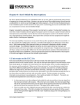
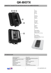
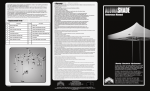
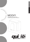
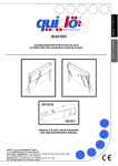
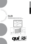
E
N
G
L
I
S
H
us e r
ma
nu
al
Hydro
HYDRAULIC SWING GATE OPENER
V04/2014
Installation limits per leaf
Limiti di’impiego per anta
Contraintes d’utilisation
2m
QK-H400 / QK-H400BC 1100kg
2,5m
3m
3,5m
4m
4,5m
5m
6m
1000kg
900kg
850kg
800kg
750kg
700kg
600kg
The values shown within the table above can be considerably reduced in windy areas.
I valori mostrati nella tabella sopra possono essere ridotti considerevolmente in zone ventose..
Les valeurs indiquées dans le tableau peuvent être considérablement réduits dans les zones venteuses.
E
N
G
L
I
S
H
Before
e installing
i
the automation, you must check that the gate’s shutter:
-
The leaf turn freely in the hinges and without sticking in the ground
It does not swing during its movement;
is kept in axis by the special hinges;
the leaves have the proper stoppages when opening and closing.
Quiko
ko IItaly Sas is liable only for products it manufactures and commercializes. Once
automated,
ted the gate becomes a machine and is therefore subjected to the rules of the “
Machinery
yD
Directive”. It is on the installer to verify its security. WARNING: Quiko Italy Sas is
not liable for
o any damages to people, animals or things due to unauthorised modification
ns,
alterations orr betterments on its products by third parties.
GENERAL
A ADVICE
Install a gate’s
ga
safety system that complies with current regulations. Choose short routes
s
for cables
ble and keep power cables separate from control ones. Install the control card in a
waterproof
terp
box.
Please refer to current regulations when setting the gear motor’s maximum torque.
Ple
We advice you to install an outdoor switch, in compliance with European standards on the
issue of safety, to turn the electricity off when servicing the gate.
Check that each single installed device is efficient and effective.
Affix
ffix easily readable signs warning about the presence of a motorised gate.
USE
It is absolu
utely forbidden to use the device for any other purposes. Installed control board
rd
(which must
st have built-in electric friction), allows selecting the following functions:
automatic: one control impulse will open or close the gate;
semi-autom
matic: one control impulse will open or close the gate.
In case of blackout,
b
act on the manual unlocking device and move manually the gate.
t
Rememberr that this is an automatic device powered by electricity, consequently use with
th
care. In pa
particular, remember:
- not to touch the device with wet hands and/or wet or bare feet;
- to
o tturn off electricity before opening the control box and/or actuator;
- not to pull the lead to pull the plug out;
- to put the gate in movement only when it is completely visible;
- to keep out of the gate’s range of action if it is moving. Wait until it has stopped;
- not to let children or animals play near the gate;
not to let children use the remote control or other operating devices
no
3
INSTALLATION MATERIALS
Fig.1
1–
2–
3–
4–
5–
6–
7–
8–
9–
10 –
11 –
12 –
13 –
14 –
4
Bracket to wall Length 130 mm
Bolt M12 X 30 with Nut
Bolt M12 x 55 with Nut
Bracket, to be weld to the leaf, length 65 mm
Bushing
Cylinder cover
Manifold
Tie rod cover
Cup
Release valve (for emergency manual operating)
Fastening covers screws
Breather screw
Release valve key
By pass valve (adjusting the piston thrust)
E
N
G
L
I
S
H
INSTA
ALLATION
1-- Arrange
A
the electric cables installation and connection according to the below Fig.2
Fig. 2
Fig 2
Unloos
se and remove the two screws # 11 (fig 1) that fastens the tie rod cover to the
cylinderr.
Assemble:
- the wall brrackets # 1 to cylinder bracket by means of the bolt and nut # 2
- the leaf bracket
b
# 4 to cylinder rod by means of the bushing # 5 and bolt / nut # 3
2-
3- Preas
assemble the cylinder to the gate according to the fig 3 and table 1
5
Fig 3
QK-H400
QK-H400BC
= 90°
= 95°
B (mm)
B (mm)
A
A (mm)
(mm) min max
min max
ax
110 120 250
120 120 22
220
120 120 250
130 120 220
150 120 250
160 120 210
200
210
220
230
120
120
120
120
190
190
180
160
210
220
230
240
120
120
120
120
160
160
130
120
Table 1
4-
Temporary fix the actuator to the wall and to the leaf (tack weld) and turn the leaff ga
gate
from the close position up to the max. open position (normally 95°) and check that the
he
leaf turn freely in the hinges and without any swing during its movement.
5- Provide to complete the assembly of the actuator to the wall and to gate leaf.
6-
Connect to the power supply cable 4x1,5 mm2
the yellow-green wire = ground
grey or blue wire = common
black wire = phase
brown wire = phase
6
E
N
G
L
I
S
H
7- Proc
oceed with the control board programming (see the CONTROL BOARD USER
MANUAL )
MA
Adjust the actuator thrust acting with the screwdriver on the by pass valves #14
Ad
The opening and closing forces
transmitted to the gate by the
cylinder are regulated by
adjusting two by pass valves.
The blue valve adjusts the
opening pressure.
The red valve the closing
pressure.
Fig. 4
+ increase the actuator thrust
- decrease the actuator thrust
8- After
er installation take away the breather screw from the actuator Fig. 5
Fig. 5
7
MANUAL UNLOCKING
To release the opening and operate the leaves manually insert and turn the release key ass
shown within in the Fig. 6
Fig. 6
8
E
N
G
L
I
S
H
Risk Areas on Hinged Gates (figure 7)
LEGEND OF MECHANICAL RISKS CAUSED BY MOVEMENT
LEG
In accordance with the Regulation on Machinery, the
following definitions are applicable:
plicable:
“Danger Zones:” any area inside and/or near a
machine where the pressence of a person is a risk
to his/her health and saffety.
“Exp
xposed Person:” any person located entirely or
partial
ally in a danger zone
e.
Impact
B
E
C
A.
A
F
D
B.
Crushing
D. Conveyance
C. Insulation
E. Cutting
F. Slicing
The installation must take a close risk examination to prevent crushing conveying cutting,
grappling trapping so to guarantee a safe installation for persons animal and objects. Refer
gr
to the law applicable in the country where the installation takes place.
9
DECLARATION OF CONFORMITY
(OF THE MANUFACTURER)
Manufacturer: QUIKO ITALY SAS
Via Seccalegno, 19
36040 Sossano (VI)
Italia
hereby declares, under his liability, that the products:
QK-H400, QK-H400BC
are in compliance with the essential safety requirements of the regulations:
Electromagnetic Compatibility Directive .........................2004/108/EC
Low Voltage Directive ......................................................2006/95/EC
Machinery Directive .........................................................2006/42/EC
and their amendments and modifications, and with the regulations set forth by the
National Legislative Body of the country in which the machinery is destined for use.
Sossano, 1//201
10
Managing Director
Luca Borinato
DECLARATION OF CONFORMITY
(OF THE INSTALLER)
The undersigned:
Address:
in charge of the set-up, declares that the product:
Gate type:
Location:
are in compliance with the essential safety requirements of the regulations:
Electro magnetic Compatibility Directive .........................2004/108/EC
Low Voltage Directive ............................................................2006/95/EC
Machinery Directive ................................................................2006/42/EC
and also declares that the related and/or specific national technical regulations have been
followed:
EN 12453/EN 12445 on Industrial, Commercial and Residential Gates and Doors – Safe
Use of Motorized Doors – Requirements and Classification – Test Methods;
EN 12604/ EN 12605 on Industrial, Commercial and Residential Gates and Doors –
Mechanical Aspects – Requirements and Classification – Test Methods;
CEI 64/8 Electrical Systems Using Nominal Tension Not Higher Than 1000V a.c. and 1500
V d.c.;
EN 13241-1 (Industrial, commercial and garage doors and gates), conformity evaluation
(6.3).
Notes:
Place and date: ………………………………………
11
QUIKO ITALY
Via Seccalegno, 19
36040 Sossano (VI) - Italy
Tel. +39 0444 785513
Fax +39 0444 782371
[email protected]
www.quikoitaly.com
The Manufacturer can technically improve
the quality of its products without
any prior notice.