Download LD-I ELEVATOR LOAD DETECTOR USER MANUAL
Transcript
ALPHA TECH
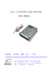
LD-I ELEVATOR LOAD DETECTOR USER MANUAL
LD-I ELEVATOR LOAD DETECTOR
USER MANUAL
ZHUHAI
ALPHA
E&M
CO., LTD.
Add:4th Floor No.1200 Jiuzhou Road Zhuhai China
Tel:0756-3326073 3326175 Fax:0756-3326352
Web:http://www.alpha-lift.com E-Mail:[email protected]
Mobile : 13326621995
13326678909
1
ALPHA TECH
LD-I ELEVATOR LOAD DETECTOR USER MANUAL
LD-I elevator load detector is designed for detecting the load of the elevator, It Can put
out switch signal and analog signal to elevator control system and inverter。
A、principle
This system is based on Hall effect. it is composed of a control device , ds11-3 sensor
a piece of alnico。
It can put out light load ,full load and over load switch signals ,it can also put out analog
Voltage output(0~10V)and analog current output(4~20mA).
Position :under the car of elevator
CABLE
B、Character
of
LD-I
1.It is easy to fix,sensor is fixed under the car 。
2.Based on Hall effect ,no actual contact to the car of elevator.Mcu control, having menu to
set parameter。
3.Can set the value of light load , full load and over load of elevator。
C、Parameter of LD-I
POWER:DC24V±15%。
OUTPUT OF RELAY: DC 60V 0.3A。
INPUT:DC 15-30V 。
Distance from alnico to sensor DS11-3 is 15-45mm, best effect
DS11-3 outline:φ22×97 (unit: mm)。
LD-I controller outline:155×105×42
(unit: mm)。
2
distance :20-35mm。
ALPHA TECH
LD-I ELEVATOR LOAD DETECTOR USER MANUAL
D、Terminal
1-2:POWER,DC24V, 1 TO +24V, 2 TO GND。
3:COM1:common terminal of OUT1, OUT2 and OUT3。
4:OUT1: light load output。
5:OUT2: full load output。
6:OUT3: over load output。
7-19: not used 。
20:The GND of power to the sensor — to DS11-3 black wire。
21:DS11-3 sensor ’s signal — to DS11-3 yellow wire。
22:The 12V+ of power to the sensor — to DS11-3 red wire。
23:4-20mA Analog output IOUT- 。
25:4-20mA Analog output IOUT+ 。
24:0-10V Analog output VOUT- 。
26:0-10V Analog output VOUT+ 。
3
ALPHA TECH
LD-I ELEVATOR LOAD DETECTOR USER MANUAL
E、LD-I MENU operation
The LD-I Operation menu has 11 sub menus:
They are :
1、empty load learning。
2、full load learning。
3、floor memory learning-not used。
4、set rated load(for example: 1000Kg OR 2000Kg …)
。
5、set light load-(for example: 100Kg 200Kg…)。
6、set over load-(for example: 1150Kg 2300Kg…)。
7、floor mode- this parameter must be set to over 200;for example: 300 or 400。
8、set full load-(for example: 950Kg)。
9、set the output(nc or no of the relay) of light load。
a、set the output(nc or no of the relay) of full load。
b、set the output(nc or no of the relay) of over load。
1、Empty load learning
Elevator is at the main floor (the first floor)and the load is guaranteed to be empty。
Adjust the distance from alnico to sensor to be about 35mm。
Press
1.Empty load learning
2.Full load learning
3.Floor memory learning
4.Set the rated load
5.Set the light load
6.Set the over load
7.Set the floor mode
8.Set the full load
9.Set the output of light load
a.Set the output of full load
b.Set the output of over load
ENTER button as follow:
Now it is in empty learning mode ,the operator leave the car roof ,after 30 seconds ,the learning
process will end 。
4
ALPHA TECH
LD-I ELEVATOR LOAD DETECTOR USER MANUAL
2、 Rated load learning
Elevator is at the main floor (the first floor)and the load is guaranteed to be rated load.
If the distance from alnico to sensor is less than 18mm. Adjust the distance to 18-20mm,
after
rated load learning , do empty loadlearning again
as follow:
Press
ENTER button as follow:
Now it is in rated load learning mode ,the operator leave the car ,after 30 seconds, the learning
process will end 。
3、Floor memory learning – not used
4、Set the rated load
Press MENU button ,select 4 as follow:
Press ENTER button,press▲and ▼button to set elevator rated load as 1000Kg,as follow:
5
ALPHA TECH
LD-I ELEVATOR LOAD DETECTOR USER MANUAL
Press ENTER button to save the value and return.
5、Set the light load
Press MENU button ,select 5 as follow:
Press ENTER button,press▲and ▼button to set elevator light load as 200Kg,as follow:
Press ENTER button to save the value and return.
6、Set the over load
Press MENU button ,select 6 as follow:
Press ENTER button,press▲and ▼button to set elevator over load as 1100Kg,as follow:
Press ENTER button to save the value and return。
6
ALPHA TECH
LD-I ELEVATOR LOAD DETECTOR USER MANUAL
7、Set the floor mode –not used
The value of this menu must be set to over 200 ,
For example: 300 or 400.
8、 Set the full load
Press MENU button ,select 8 as follow:
Press ENTER button,press▲and ▼button to set elevator over load as 920Kg,as follow:
Press ENTER button to save the value and return.
9、Set the output(NC or NO of the relay) of light load
Press MENU button ,select 9 as follow:
Press ENTER button,press▲and ▼button to set the value。
If the value is zero, the output of light load is NC (normal close)。
If the value is not zero, the output of light load is NO (normal open)。
Press ENTER button to save the value and return。
7
ALPHA TECH
LD-I ELEVATOR LOAD DETECTOR USER MANUAL
a、 Set the output (NC or NO of the relay) of full load
Press MENU button ,select “a” as follow:
Press ENTER button,press▲and ▼button to set the value。
If the value is zero, the output of full load is NC (normal close)。
If the value is not zero, the output of full load is NO (normal open)。
Press ENTER button to save the value and return.
b、Set the output(NC or NO of the relay) of over load
Press MENU button ,select “B” As follow:
Press ENTER button,press▲and ▼button to set the value 。
If the value is zero, the output of over load is NC (normal close)。
If the value is not zero, the output of over load is NO (normal open)。
Press ENTER button to save the value and return.
8
ALPHA TECH
LD-I ELEVATOR LOAD DETECTOR USER MANUAL
F、Adjusting Process
The DS11-3 sensor is fixed under the car toward the alnico.
First set four parameters:
Menu 4: set rated load
Menu 5: set light load
Menu 6: set over load
Menu 8: set full load
After setting the four parameters. Let the car to be empty !
Menu 1: empty load learning
After empty loadlearning, Let the car to be rated load!
Menu 2: rated load learning
At last , the value of menu 7 must be set to over 200
For example: 300 or 400。
G、Note:
1.Be careful , The alnico is easy to be broken.
2.Do not let the alnico contact substance which the temperature is more than 150 ℃
H、Deal with fault:
1.LED display 9999,the output of relay are not right。
Cause A: Have not studied empty load and rated load.Or have not set the values of rated load ,
empty load, light load and full load 。
Cause B:The value of menu 7 must be set to over 200 。for example: 300 or 400。
2. LED display 0000,the output of relay are not right。
Cause A:the output of Ds11-3 sensor is not right.Please check the ds11-3 sensor or replace it
with a good one。
Cause B:The power of the sensor is not right .it should be DC12V.Please check whether the voltage
between the terminal 20 and 22is DC12V。
Cause C:The position of the alnico is not right 。Turn over the alnico and try again!
9


