1
MPG LEVEL 1
Chapter 9: Don’t Mind the Interruptions
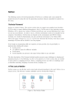
We have a great foundation for our embedded system set up now, and you could already write a bunch
of programs to do some neat things. However, we want to have a fully enabled system that will provide
a solid platform on which we can build bigger and better programs. One of the most fundamental parts
of an embedded system revolves around interrupts, and it is something you must be comfortable with if
you are going to be serious about embedded design.
Chapter 1 provided an overview of the concept of an interrupt in a system. The idea itself is simple: any
event that needs immediate attention grabs the program counter to execute a special function called an
interrupt service routine (ISR), runs the ISR, then returns the program counter to the location where it
was interrupted from in the first place. The program then continues its linear progression through the
code in flash as if nothing ever happened.
The interrupt capability of a processor is very much like any other peripheral on the microcontroller. It
has bits and bytes for configuration and status, and will provide signals to the MCU about events that
occur. Solid understanding of the interrupt system on a processor is absolutely critical to creating
successful designs. The embedded Engineer can define an entire system driven by interrupts and
optimize system performance and power consumption by using interrupts. Though each processor core
will have a unique set of rules that define how the interrupt hardware operates, the fundamentals can
be easily carried across all platforms. Once you get past the syntax and understand the critical aspects
of the interrupt engine, then you are free to build a great system.
9.1 Interrupts on the LPC214x
Every microcontroller and microprocessor will have at least a few interrupt sources that provide
powerful control to the firmware system. Not only do interrupts allow signals to be prioritized to ensure
that critical signals are handled in a timely fashion, but they also allow access to unique capabilities of
the processor and its peripherals. When we say “interrupt source” we are referring to simple binary
inputs from different peripherals that the processor can detect, stop what it is currently working on,
address the single source, and then resume what it was doing. Interrupts can come from the GPIO
peripheral (like a button press), from timers when they expire, from communication peripherals that let
you know when new data has arrived, and many other sources. The key concepts surrounding
interrupts on any processor are quite general – this is what we looked at in Chapter 1. The points are
reviewed and expanded here since they are so important:
1. An interrupt source must be configured and enabled in order to provide an interrupt signal that
the interrupt controller will recognize. If the interrupt is not enabled, the interrupt signal (flag)
will still be asserted with the event, but the signal will be ignored by the interrupt controller and
will thus not cause the processor to branch. This signal can be polled instead.
2. There is usually some sort of global interrupt enable (GIE) bit that must also be set to allow any
interrupts to be active. If the GIE is disabled, the individual interrupt signal will still be present
and an interrupt will be triggered if the GIE is later enabled (as long as the interrupt flag has not
been cleared).
notes_mpgl1_chapter9.docx
Release 1.0
Page 1 of 23
MPG LEVEL 1
3. When an interrupt occurs, an ISR is called automatically based on the source of the interrupt.
Note that “called” is not the best term to use. A more correct explanation is that the program
counter moves to the address of the ISR based on flags and configuration of the interrupt
controller. Generally every interrupt source that is enabled will have its own unique ISR.
4. On the LPC214x processors, two hardware priority groups are available. The high priority
interrupt is referred to as FIQ and the low priority interrupt is the IRQ. The low priority ISR can
be interrupted by the higher priority interrupt. Another way to say that is that a high-priority
interrupt can pre-empt a low-priority interrupt. Multiple interrupt sources can be assigned to
either of the two groups using configuration registers.
5. Active interrupts of the same hardware priority can be prioritized in firmware, so even if two
interrupts occur simultaneously, the higher priority interrupt can be serviced first.
6. An interrupt source can occur even if its ISR is already executing. Since interrupts of the same
priority level are disabled while an ISR runs, the new interrupt event will not have any impact
until the current ISR exits. The interrupt signal will trigger another call to the ISR as soon as the
interrupts are re-enabled as the ISR exits, unless the ISR has cleared the new source event flag.
7. An interrupt can occur at any time and in any place in the code (as long as the required interrupt
enable bits are set). This means the program must be able to survive being interrupted at any
point. If there are places where the program simply cannot survive if it is interrupted, then
interrupts must be disabled during that part of the code – a handy use of the GIE bit.
8. When an interrupt occurs, the program “context” is saved so that resources can be used to
execute the ISR code without destroying values in locations that maybe overwritten during the
ISR. The PC, CPSR, LR and other registers need to be saved and are done so automatically by the
LPC214x (other processors do not automatically save registers for you, and leave it up to you to
decide what needs to be saved). If you use other resources that are shared in the main code
and ISR, then those resources must be saved as well. For example, say you have a scratch
register “temp” that you use all the time for temporary storage. If the ISR uses “temp” as well,
then it must be saved first and restored on exit. If you have global variables that are accessed in
interrupt service routines, you need to be very careful on how these are managed.
9. An ISR should execute as quickly as possible. When complete, the system context must be
restored (the LPC214x does this for you as well) and the ISR returns and re-enables interrupts.
There are many different interrupt sources on the LPC family of processors. Each can be enabled
individually, and you can have many different interrupt sources active. No matter what interrupt source
you are working with, the above rules apply to the behavior of that source. In this chapter we will look
at two of the interrupt sources that will be used on the development board: GPIO and Timer. There are
many others that we will take a quick look at here before diving into some greater detail.
9.1.1 GPIO Interrupts
Interrupts that come from sources external to the microcontroller are very powerful and are often a key
element in low-power design since the processor can be in sleep mode until it is woken up by an
external event. Buttons are a great example. Using a button interrupt source saves you polling for the
button signal and allows user input to be sensed instantly without wasting any time. It also essentially
eliminates the chance of missing an input signal since the signal is detected in hardware and not cleared
until the processor sees it and acknowledges it (even if the original signal source has long-since
vanished). Input sources can be extended beyond buttons to things like encoders, where fast signals can
be read from other circuits. Other devices in the system can provide wake-up signals as well on GPIOs.
notes_mpgl1_chapter9.docx
Release 1.0
Page 2 of 23
MPG LEVEL 1
9.1.2.1 Spurious Interrupts
A problem that sometimes crops up with external interrupts extends from the very nature of an
interrupt in that they are not determ
deterministic.
inistic. While you can generally predict and account for interrupt
sources local to your microcontroller, when they are coming from external sources through GPIOs you
are at the mercy of the real world, or worse, at the mercy of other embedded designers who built
circuits that interface to your system
system. Even if a system is built very well, the
he world is full of nasty things
that can impact digital signal quality. The real world also contains a lot of mistakes that can send signals
when there should not be any signals present. Though communication protocols can be designed and
implemented carefully, there is nothing that guarantees that everything works the way it should.
Spurious interrupts are those that occur when they should not, or at least when you do not want them
to occur.. If you are trying to do something in your code and interrupts are happening so fast that your
processor cannot devote any time to its main task, then you can have problems. Connecting and
disconnecting external lines, electrost
electrostatic
atic discharge (ESD) or power supply noise / transients are all
potential sources of spurious interrupts. In many embedded systems, you either do not have problems
like this, or if you do, you do not actually care. If you have problems and you do care, then
t
you have to
either figure out how to stop them, or at least figure out how to deal with them in firmware. You should
not have to worry about spurious interrupts for the duration of this course, but it was a good time to
plant the seed in your mind so you can look out for it in the future. Once you enable interrupts in your
system, you can get some truly bizarre behavior.
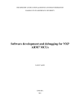
Once interrupts are active on the development board, you might find that the JJ-Link
Link debugger has
trouble finding the processor when
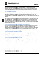
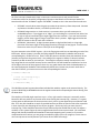
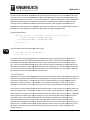
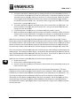
n you start the debugger. If you see the message shown in Figure
9.1.2.1.1 pop up when you try to load your code
code,, you need to click “Abort” and let the debugger crash.
Take this as a reminder to put your development board in “boot loader” mode i.e. holding
hold BUTTON1
while pressing and releasing the reset button so that the processor resets but does not start running
interrupt code. This is an irritating “f
“feature” of IAR / ARM / J-Link
Link (not sure whose fault it actually is).
Figure 9.1.2.1.1: Error message
ge when debugger is launched and dev board is running interrupt code
9.1.2 Timer Interrupts
Timer
imer peripherals can be interrupt sources and cause interrupts for various reasons. The most common
use is signaling the core when the timer overflows. Though that
at might not sound like a big deal, timer
interrupts enable some of the most powerful features of an embedded system. For example, a timer
interrupt can provide a system tick that will maintain a very accurate reconciliation of elapsed time in
the system. Even if the system does not use real time (as in the exact month, day, hour, second, etc.) a
system tick can be relative to the time when the device is first activated. If priorities are available, the
system tick is usually given the highest possible priority to ensure the most accurate period.
notes_mpgl1_chapter9.docx
Release 1.0
Page 3 of 23
MPG LEVEL 1
In addition to keeping great time, timer interrupts facilitate low power operation of embedded systems.
Many embedded systems spend most of their time doing nothing. If there is nothing to be done, the
core can go to sleep and consume very little power. Often a timer peripheral can run independently
from the core and by itself consume much less power. Going back to a simple 1-Hz
Hz LED blinking
program, a processor could be sleeping for 499,990 instruction cycles, be wo
woken
ken up by the timer to
toggle the LED, then go back to sleep. This can drastically reduce overall power consumption. A timer
interrupt is going to cure our variable 1ms system tick problem and allow us to sleep the
microcontroller.
9.1.3 Communication Peripheral Interrupts
Communication peripherals usually provide a bunch of interrupt signals to do things like let you know
when receive buffers are full or transmit buffers are empty. They may also indicate various errors or
warnings that the system can respond to and make sure data flows properly. Each peripheral will have
its own interrupts, so multiple communications peripherals can be wired in to provide a very nice
interrupt-driven
driven system that will manage many data streams in and out of the processor.
processo This allows
high data rates to be maintained without ever missing a byte (in these cases, it becomes important to
ensure ISRs execute very quickly and are properly prioritized to handle the highest speed data). This is
something that would be potentially
lly impossible to manage by polling for data.
9.1.4 Other Peripheral Interrupts
There are many other interrupt sources available on the LPC214
LPC214x and on other processors. Though
timers, communications and GPIO typically make up most interrupt sources, there are always a few
unique interrupts available on microcontrollers that can come in handy. Whenever you begin working
with a microcontroller that you have not had experience with, reading and understanding the available
interrupts and how the processor mana
manages those interrupts is extremely important.
9.2 Interrupt Configuration
Now that you have the basic understanding of interrupts, we will take a detailed look at getting them up
and running on the LPC214x processor. Admittedly, the ARM7 interrupt structure is fairly complicated
when compared to more simple 8-bit
bit and 16
16-bit architectures. This is partially due to the way an ARMARM
based microcontroller is put together because the interrupt controller is part of the core, yet the
microcontroller vendor will have
ve a number of peripheral interrupts that they want to use. It
I will all
make sense once you have gained some experience with it.
The hardest part is learning some of the syntax to make a program in C properly configure and respond
to interrupts – that will all be detailed carefully here. As with any new peripheral you want to learn, you
should start by reading the appropriate section in the datasheet, which is Chapter 7 of the LPC214x
LPC21 user
guide. Take a look at that now, even if you do not understand everything you read. As an embedded
designer, this is the approach that you typically have to take when learning. You should always have the
user guide open to the relevant section of the processor that you are working on.
The whole interrupt mechanism on the LPC214x is called the Vectored Interrupt Controller or VIC for
short. Basically that means that the interrupt controller works by branching (“vectoring”) to different
notes_mpgl1_chapter9.docx
Release 1.0
Page 4 of 23
MPG LEVEL 1
addresses depending on what source caused the interrupt. To make it do this, interrupt configuration
requires you to do the following (roughly in this order):
1.
2.
3.
4.
Identify the interrupt sources you want to use in the design
Setup the VIC registers to tell the VIC what interrupts you want to use and their priorities
Enable the selected interrupts
Write interrupt service routines to handle the enabled interrupts
If the VIC is completely set up and the rest of the relevant processor functionality is configured, only
then should you enable the global interrupt bits to let the system start responding to and servicing
interrupt requests. Typically this is done just before the main program loop is entered and every other
setup register is loaded.
9.2.1 Interrupt Types
When the user guide introduces the VIC, it classifies them into three types:
1. Fast Interrupt reQuest (FIQ)
2. Vectored Interrupt ReQuest (IRQ)
3. Non-vectored interrupt
However, as you read on in the user guide you can see that there are really only two types of interrupts
– FIQ and IRQ – since the non-vectored interrupts are a subset of the IRQ classification. The guide also
says that the VIC provides 17 levels of prioritization – this is sort of true. One might argue that interrupt
priority means that if any ISR is running and a higher interrupt priority occurs, then the current
ISR will be pre-empted and the ISR of the higher priority interrupt will be launched. This is true between
FIQ and IRQ interrupts. If any IRQ ISR is running and an enabled FIQ occurs, the IRQ ISR is stopped while
the FIQ ISR runs. Once the FIQ is finished, the IRQ resumes. When the IRQ is done, the main program is
resumed.
If an IRQ ISR is running and another IRQ interrupt occurs of higher priority, the current ISR finishes
before the next one starts – there is no pre-emption. That being said, if more than one IRQ occurs
simultaneously, or if IRQ interrupts are temporarily disabled and several sources have generated
interrupts during that time, then hardware will prioritize the execution of ISRs when interrupts are reenabled. In this sense, IRQ interrupts have multiple hardware levels of priority.
If you remember looking at the status register on the LPC processor, there is an enable bit for FIQ and
another enable bit for IRQ interrupts. This gives hardware global control over the two groups of
interrupts (in other words, this processor has two GIE bits). When an IRQ interrupt is active, the IRQ bit
is clear so no other IRQs can interrupt an IRQ ISR. However, the FIQ GIE is still set which allows an FIQ
interrupt to occur during an IRQ ISR. If the processor is running normally and an FIQ occurs, both the
FIQ and IRQ bits are cleared while the FIQ ISR executes so that an IRQ cannot interrupt the processor.
Once the FIQ ISR completes, both GIE bits are set. If no interrupt sources have fired during the FIQ, the
processor goes back to normal operation. If an IRQ had occurred during the FIQ, then the processor will
jump to the IRQ ISR as soon as the FIQ ISR exits.
notes_mpgl1_chapter9.docx
Release 1.0
Page 5 of 23
MPG LEVEL 1
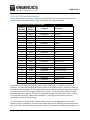
9.2.2 LPC2142 Interrupt Sources
The LPC214x processor architecture supports up to 32 different interrupt sources, though only 23 of
them are used on the LPC214x family. Table 9.1 shows all of the sources available.
Table 9.1 LPC214x Family Interrupts
Source #
(Decimal)
Source #
(Binary)
Hex Mask
Description
0
1
2
3
4
5
00000
00001
00010
00011
00100
00101
0x00000001
0x00000002
0x00000004
0x00000008
0x00000010
0x00000020
Watchdog Timer
Reserved
ARM Core0
ARM Core1
TIMER0
TIMER1
6
7
8
9
10
11
00110
00111
01000
01001
01010
01011
0x00000040
0x00000080
0x00000100
0x00000200
0x00000400
0x00000800
UART0
UART1
PWM0
I2C0
SPI0
SPI1 / SSP
12
13
14
15
16
17
01100
01101
01110
01111
10000
10001
0x00001000
0x00002000
0x00004000
0x00008000
0x00010000
0x00020000
Phase Lock Loop
Real time clock
External Interrupt 0
External Interrupt 1
External Interrupt 2
External Interrupt 3
18
19
20
21
22
10010
10011
10100
10101
10110
0x00040000
0x00080000
0x00100000
0x00200000
0x00400000
Analog 0
I2C1
Brownout Detector
Analog 1
USB
The number of each source is important as this number corresponds to its physical connection in
hardware. The value has nothing to do with the priority of the interrupt source. Each source from the
table above can be assigned as an FIQ or IRQ and will have its own ISR. Where the interrupt is assigned
in the interrupt vector control registers determines its priority. Once interrupt functionality is setup,
hardware takes care of the rest. The table also shows the hexadecimal mask of the interrupt. Each of
the 32 possible sources has a flag bit associated with it. These flag bits are used for certain VIC
functionality that we will look at shortly.
It is also important to note that each of these interrupt sources can be triggered from a variety of
different signals in a peripheral, so there can be multiple flags that the ISR needs to check to determine
the source. This is up to the programmer to take care of. For example, the UART0 interrupt source can
notes_mpgl1_chapter9.docx
Release 1.0
Page 6 of 23
MPG LEVEL 1
be triggered from the transmit hardware, the receive hardware, or two other signals from the
peripheral. Therefore, we will see that any ISR written to handle a particular interrupt source must
include code to determine how the interrupt was triggered if multiple trigger sources are enabled.
9.2.3 Interrupt Registers
There are 43 registers associated with the VIC, though 33 of tthem
hem have the same functionality applied to
each of the various IRQ interrupt sources. The datasheet looks at each one in detail giving you a
description of the purpose of the register, a bit map, and description of what each bit does. That
information
tion will not be repeated here, but we will discuss a few of the most important registers that will
be used.
Now would be a good time to download the Chapter 9 start code so you can look at the interrupt code
as it is being discussed. All the interrupt setup code is in place for you as it would be a bit too much
information to explain and to do at the same time, especially if you are new to interrupts in general.
You will have the opportunity to write some ISRs in this chapter, and in later chapters we will configure
more interrupts in the system.
9.2.3.1 Interrupt Enable Register
Registers (VICIntEnable and VICIntEnClear)
Each interrupt source must be individually enabled before the VIC will use the signal to interrupt the
processor. There is one enable bit for every interrupt source, and the bit corresponds to the
hexadecimal bit mask value that was shown in Table 9.1. For example, if you wanted to enable UART0
interrupts, then you would OR the hex value 0x40 to the Interrupt Enable Register to set bit 6. If at
some point you wanted to disable the UART0 interrupt, you would write 0x40 to the interrupt enable
clear register. The registers are detailed on page 68 and 69 in the reference manual.
9.2.3.2 Interrupt Select Register (VICIntSelect)
The Select registerr is used to assign an interrupt source to either the FIQ group (bit is set) or the IRQ
group (bit is clear). Again, the bit numbers correspond to the interrupt numbers in Table 9.1.
The designer should be careful to make this distinction and use the high priority interrupts for signals
that MUST be serviced with very little latency. See page 70 in the user guide.
9.2.3.4 Vector Control Registers (VICVectCntlx)
There are 16 “slots” available in the IRQ group of interrupts where each slot can hold the address
add
(vector) of an interrupt service routine. The control registers are used to tell the VIC hardware which
slot it should look at to find the address of the interrupt service routine for a given IRQ interrupt. The
lower the slot, the higher the priorit
priority of the interrupt. For example, the code for this chapter makes the
following assignments to setup the button interrupts
interrupts:
VICVectCntl0
VICVectCntl1
VICVectCntl2
VICVectCntl3
=
=
=
=
VICVectCntl0_INIT;
VICVectCntl1_INIT;
VICVectCntl2_INIT;
VICVectCntl3_IN
VICVectCntl3_INIT;
where the INIT values are defined as:
#define VICVectCntl0_INIT (VIC_EINT0 | 0x20)
#define VICVectCntl1_INIT (VIC_EINT1 | 0x20)
notes_mpgl1_chapter9.docx
Release 1.0
Page 7 of 23
MPG LEVEL 1
#define VICVectCntl2_INIT (VIC_EINT2 | 0x20)
#define VICVectCntl3_INIT (VIC_EINT3 | 0x20)
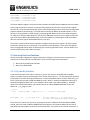
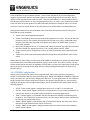
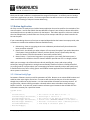
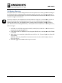
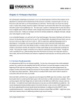
VIC_EINTx is a constant for the interrupt source’s number from Table 9.1. The ORed value of 0x20 sets a
flag to enable that slot. Figure 9.2.3.4.1 shows the bit description from the data sheet.
Figure 9.2.3.4.1: Bit description table for VICVectCntrl registers
Source: LPC214x User manual Rev. 3 – 4 October 2010, UM10139, NXP Semiconductors, pg. 71
So given those assignments, if the EINT0 (external interrupt 0) signal is enabled as an interrupt source
and the interrupt occurs because BUTTON0 was pressed, the VIC will look at all the VICVectCntl registers
for EINT0. When it finds it (in slot 0) it knows that the address of the ISR for EINT0 will be in a
corresponding slot 0 address register.
If BUTTON0 and BUTTON1 are pressed at exactly the same time, the EINT0 ISR will run first because it
has a higher priority. What the ISR is done, it will exit and start to return to the main program, but then
immediately repeat the interrupt process to handle the BUTTON1 interrupt. Though it technically
handles each button press individually, a user would never be able to tell that BUTTON0 is handled first
since it would be only a few microseconds of time between the ISR processing. You can test this later on
in the chapter when we will make LEDs turn on when buttons are pressed (actually, it is all a moot point
because you will never be able to press the buttons at exactly the same time!).
The last thing to note about the control registers is that if an enabled IRQ has not been given a slot, then
the program counter will be loaded with the default ISR address (VicDefVectAddr). We have not yet
identified any of these address registers yet, so we will do that next.
9.2.3.3 Vector Address Registers (VICVectAddrx)
Directly related to the Vector Control registers are the Vector Address registers. These are the “slots” in
the IRQ that must be loaded with the addresses of the ISRs for the interrupts configured in the control
registers. The setup code for this chapter loads the first 4 slots with the addresses for the button
interrupt service routines:
notes_mpgl1_chapter9.docx
Release 1.0
Page 8 of 23
MPG LEVEL 1
VICVectAddr0
VICVectAddr1
VICVectAddr2
VICVectAddr3
=
=
=
=
(u32)&Button0ISR;
(u32)&Button1ISR;
(u32)&Button2ISR;
(u32)&Button3ISR;
The Vector Address registers are simply memory locations that hold function addresses that are loaded
to the program counter to cause it to jump and start executing that function very much like a regular
function call. Since we have already seen how to call functions with pointers, the concept of using these
registers should not be too foreign. The code above is taking the address of the ISR function (i.e. the
function’s starting address in Flash memory), and loading that address to the vector address registers.
To make the C compiler happy about this, the function addresses have to be cast to (u32) to match the
type of the vector address (the default type of a function address is something like void(*)void which
does not match the type of VICVectAddrx which is just u32).
That covers virtually all of the setup required to configure interrupts in the system. All of the register
initialization is done for you in interrupts.c in the function InterruptSetup(). There are a few registers
that are configured that we have not discussed yet, but we will get there shortly. All that remains is to
write the ISR functions and enable interrupts!
9.3 Interrupt Service Routines
Once the interrupts configuration registers have been configured, you must write interrupt service
routines for all of the ISRs you have identified. There are two things that must be done:
1. Write the FIQ and IRQ main handlers
2. Write the individual ISRs
9.3.1 FIQ and IRQ Handlers
If you look back at the vector table in cstartup.s, you will see mention of the IRQ and FIQ handler
vectors. Consider these as the starting point for all interrupts that occur. The microcontroller hardware
is physically set to move the program counter to a certain flash address when an FIQ or IRQ occurs, just
like it is physically set to go to address 0x0000 on reset (“Reset” is actually considered an interrupt of
the absolute highest priority and is “non-maskable” which means you cannot disable it). Way back
when we first looked at firmware you saw how the line of code at 0x0000 loaded the PC with the
address of __iar_program_start.
__vector:
LDR
...
Reset_Addr:
PC,Reset_Addr
DCD
; Address is 0x0000 – sets PC to Reset_Addr
__iar_program_start
; Puts the address of __iar_program_start
; in memory and assigns the symbol Reset_Addr
The process of a reset is two-step: first, the program counter is loaded to the fixed address 0x0000;
second, the line of code at address 0x0000 loads the program to the dynamic address of the start of
code wherever that happens to be when you build the code. The process is the same for interrupts. If
notes_mpgl1_chapter9.docx
Release 1.0
Page 9 of 23
MPG LEVEL 1
an FIQ occurs, the hardware always goes to 0x001C. Here, the dynamic address of FIQ_Handler is
loaded to the program counter so it jumps to that function. The process is similar for the IRQ_Hanlder
(no matter what the source of the IRQ was – the processor will figure that out later).
The two handler functions themselves are written just like any other function except special syntax is
used to flag them to the compiler as being the FIQ and IRQ handlers. This makes the compiler treat the
routines as their respective interrupt types which means that extra context saving and restoration
(among other things) will be done. The syntax is strange and will likely be different on any processor or
IDE you use even though it effectively accomplishes the same thing. It is not something you would “just
know” how to do – you would have to find a description of the notation or an example that works and
copy it.
The FIQ handler looks like this:
__fiq __arm void FIQ_Handler(void)
{
} /* end FIQ_Handler */
The IRQ handler looks like this:
__irq __arm void IRQ_Handler(void)
{
} /* end IRQ_Handler */
The source code inside the IRQ handler is a bit wacky from a syntax perspective, but if you look at the
comments it should make perfect sense. The IRQ_Handler code is as follows:
{
/* Parse the interrupt and call the correct IRQ ISR. Interrupts remain off, though
FIQ can interrupt this function */
void (*interrupt_task)();
u32 u32Vector;
/* Get interrupt vector and acknowledge it */
u32Vector = VICVectAddr;
VICVectAddr = 0;
/* Execute the task associated with this interrupt */
interrupt_task = (void(*)())u32Vector;
(*interrupt_task)();
} /* end IRQ_Handler */
The code comes directly from an IAR example program, though the comments were added to help
clarify what is happening. Essentially the address of the interrupt is provided by hardware (thanks to all
of the configuration that was done already in the VIC registers) and the ISR is then called using the
function’s address. The line that writes 0 to VICVectAddr is critical to acknowledge the IRQ interrupt.
Again, there is nothing that would allow you to just know that, although from your general knowledge of
interrupts you might suspect there must be a flag to clear somewhere to acknowledge the interrupt.
notes_mpgl1_chapter9.docx
Release 1.0
Page 10 of 23
MPG LEVEL 1
The VIC documentation describes this on page 78 (and it is admittedly hard to find!). After that, a callby-function-pointer takes place. Though the function pointer syntax looks a bit different then what was
used in Chapter 8, it does the same thing.
The FIQ handler is much simpler because it does not have control and address registers to deal with. In
general, you only have one FIQ source because you probably only need one interrupt source to be the
absolute highest priority (like a system tick). Therefore, the entire ISR code is written inside
FIQ_Handler. We will look at that code once we implement the system tick. If you wanted a few FIQ
interrupt sources, it would be up to you to prioritize them within FIQ_Handler.
9.4 GPIO Interrupts
The individual ISRs are by far the easiest part of all of this. There is no crazy syntax since these functions
are wrapped inside the FIQ or IRQ handlers. The only critical thing to remember is to clear the
peripheral interrupt bit that caused the interrupt or else you will be stuck servicing the interrupt forever.
GPIO interrupts are a good place for us to start because you will be in control of the interrupt events.
The LPC214x processor supports external interrupts on four pins, so we will use all of them for button
inputs. The signals are named EINT0 thru EINT3. Once again we reference the user manual for
information on how to correctly configure the external interrupt sources. Of course, this was first done
a long, long time ago during the design of the development board to make sure that we correctly put
the buttons on the proper pins.
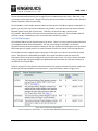
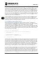
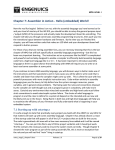
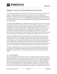
Table 13 on page 27 in the reference manual summarizes the registers that we will need to setup to use
the external interrupt capabilities of the processor. A copy of the table is shown in Figure 9.4.1.
Figure 9.4.1: External Interrupt Registers
Source: LPC214x User manual Rev. 3 – 4 October 2010, UM10139, NXP Semiconductors, pg. 27
notes_mpgl1_chapter9.docx
Release 1.0
Page 11 of 23
MPG LEVEL 1
All of the interrupt-related code is kept in interrupts.c and interrupts.h, and you will find the
initialization values for three EINT configuration registers at the bottom of the interrupt header file.
Note that IAR calls the “INTWAKE” register “EXTWAKE” instead, so that is the name that the code uses.
•
•
•
EXTWAKE: controls what external signals can wake the processor up from sleep mode. We want
any button to be able to do this, so all EINT input bits are set
EXTMODE: edge sensitive vs. level sensitive is a common choice you will come across in
embedded systems. If you trigger on an “edge”, you are looking for a transition from either low
to high or high to low and will get a single trigger from the transition. If you use level-sensitive
triggers, you will keep trigger as long as a particular level is present. Edge-triggered is what we
want for buttons so we can catch the transitions.
EXTPOLAR: “polarization” in digital systems equates to high and low levels or rising-edge
(transition from low to high) or falling-edge (transition from high-to-low) signals. Since all of the
buttons are active-low, we want to interrupt on the falling edge.
Pay extra attention to the EXTINT register – this is the flag register with bits corresponding to each of the
EINT inputs. When a button is pressed, the falling-edge will be detected in hardware and cause the
corresponding bit in EXTINT to be set. Even if interrupts were not enabled, these bits would still be set
(another concept from the general rules). You could poll this register to detect if a button had been
pressed if you did not want to use interrupts. These flag bits must be manually cleared, which is the
only thing that the current EINT interrupt service routines do. EXTINT should be initialized to 0 to clear
all the flags at the start of the program as there is a very good chance that when the board powers up,
the interrupt detection hardware could accidentally detect that a button was pressed. Note that to
clear bits in EXTINT, you must write a one to the corresponding bit location.
void Button0ISR(void)
{
/* Clear the interrupt flag */
EXTINT_bit.EINT0 = 1;
} /* end Button0ISR() */
The IAR IDE works with a syntax that allows individual bits within a register to be accessed directly. The
syntax is REGISTER_bit.BITNAME and uses the register names and corresponding bit names directly from
the data sheet.
The simplicity of the ISR might stand out to you. In fact, right now this interrupt is essentially useless
because it does not perform any function other than clearing the interrupt flag. However, it is a good
starting point to demonstrate the interrupt action nicely, and is a great opportunity to emphasize small
ISRs. As a rule, ISRs should be as simple as possible because you want to spend as little time as possible
in them since they are disrupting the rest of your program. At the very least, you must clear the
interrupt flag. There should be some other simple functionality that the ISR does as well, like adjust a
variable, or set a system flag so the main program knows that the interrupt occurred. You could have
designs with literally hundreds of thousands of interrupts happening every second, so if you write
complicated service routines, you are going to completely neglect your main program, or even start to
miss interrupt events entirely because you cannot service them fast enough.
notes_mpgl1_chapter9.docx
Release 1.0
Page 12 of 23
MPG LEVEL 1
Build the code and
nd run it on the development board. Pu
Putt a breakpoint inside Button0ISR()
Button0IS and try
pressing the BUTTON0 while the code is running. Try single-stepping
stepping out of the ISR to see where the
interrupt occurred – most of the time, you will end up back in the sleep function because that is where
the program spends most of its time.
Interrupt functionality generally does not work very well if you are single
single-stepping
stepping in code,
code especially for
catching an interrupt on the way in to the ISR (stepping out of an ISR usuall
usually works).. It seems to be
better on version 8 J-Links,
Links, but you still may get some bizarre behavior or crash the system if you try it on
older J-Link hardware.. There are ways to use breakpoints and other variables to debug interrupts if
necessary. Rememberr this point if you are trying to debug interrupts and single
single-stepping
stepping in code.
Add a Local Global debug counter in interrupts.c and then increment the counter inside Button0ISR().
Button0ISR()
Build the code and run it on the development board without any breakpoints. Halt the code and make
sure you can see that the counter is 0 in a watch window, then resume running the code. As the
program is running, press and release the button 10 times. Try quick taps, normal presses and longer
pushes – in any case, make suree you hear the button click each time you press it. After 10 pushes, halt
the code and look
ook at the button counter in a watch window – what do you see? In some cases, the
counter will be 10 as you would expect since you pressed the button 10 times. Howe
However,
ver, you might see
that it is more than 10 by a few or even by many more. Why?
The extra increments are caused by “bouncing” – mechanical imperfections that cause multiple on-off
on
connections as the button is being pressed and released. On a typical me
mechanical
chanical button, the
manufacturer will specify a “debounce” time for the button. This spec is the amount of time you should
allow the button to stabilize before deciding its final state. The processor is running so quickly, that
every little bounce will be a low-to--high transition that will be detected and cause another interrupt.
This should make it obvious then that you cannot simply set a flag in your button ISR to tell the system
that a button press has occurred because you will get a ton of false signals. You must always debounce
mechanical inputs and this
his is the first reason why we need to write a button application. Just before we
do that, though, we need another tool.
9.4 System Timing
Up to this point, any timing that has been done in our system has rrequired
equired keeping track of instruction
instru
cycles and wasting power doing nothing but running long loops to kill cycles. You do not really have a
choice because the processor core is the only resource we have available so far and it must be running
with the system clock all the time to keep track of time. What we need is a separate peripheral that will
keep track of time automatically – even when the processor core is not running. Peripherals like this are
simply called “timers.”
It is safe to say that every microcontroller will have at le
least one built-in
in timer peripheral, and probably
every embedded system you work with will use at least one timer. The LPC214x family has two timers,
TIMER0 and TIMER1.. The importance of timers in embedded systems is highlighted by the fact that
most new micros
icros have at least five timers, and some have many more than that!
notes_mpgl1_chapter9.docx
Release 1.0
Page 13 of 23
MPG LEVEL 1
Timer peripherals are just hardware counters. Like any other peripherals, they have configuration
registers to govern their behavior and status registers to report things like the current count. Do not
confuse a timer peripheral with a real time clock – they are much different. A timer peripheral has no
idea what day of the week it is or if you are getting close to lunch. It really is just a counter that usually
starts at 0 when the system powers on and will eventually overflow at a maximum value. On a 32-bit
processor, timers are usually 32-bits so they will count to over 4 billion before overflowing back to 0.
Some general statements can be made about timers to describe characteristics that are likely to be
found with any timer peripheral:
1. Timers have to be configured and enabled.
2. Timers are clocked by some clock source that the programmer can select. This may be the main
processor clock (i.e. the crystal or RC oscillator that runs the core’s clock), a dedicated crystal
that just clocks the timer (very often a low power circuit with a 32.768kHz watch crystal), or
some other oscillator.
3. Most timer peripherals can run in “counter mode” where an external logic signal will increment
the timer instead of a regular clock source. This is usually called “capture” mode.
4. Timers can be preset or configured to count to an arbitrary maximum value instead of the full
range.
5. Timers can fire interrupts and sometimes do other things when they overflow or reach certain
values.
We will see all of these things in action as we setup TIMER0 to provide the 1ms system tick and allow us
to move away from inaccurately and inefficiently trying to count cycles. Once this is in place, not only
will the system tick be precisely 1ms regardless of what code is running in the super loop, but we will be
able to put the core to sleep to save power when it is doing nothing but waiting for the current 1ms
period to tick by.
9.4.1 TIMER0 Configuration
Getting a timer peripheral to work is fairly straight forward. Open up the processor user guide to
Chapter 15 that explains how the timer peripherals work. Notice that TIMER0 and TIMER1 are identical,
so once you learn one, you can easily configure the other one. The user guide covers all of the different
things that the timer can do, but we want to focus on just the parts that will give us a 1ms time base.
Looking at the register map and register descriptions, we can conclude that we need to work with the
following registers:
•
•
•
•
•
TxTCR – Timer control register: manages when the timer is on and if it is reset back to 0
TxCTCR – Count control register: determines if the peripheral is in timer mode (clocked from an
internal clock source) or in counter mode (clocked from an external digital signal).
TxPR – Prescale register: a clock divider that will slow down the effective incrementing of the
peripheral. This is helpful if the reference clock is very fast yet you want the timer peripheral to
be counting very long periods of time.
TxMRx – Match registers: hold numbers that are compared to the current timer count. When
the two are equal, different events can be set to occur.
TxMCR – Match control register: configures events that occur when the timer value matches
specific match registers.
notes_mpgl1_chapter9.docx
Release 1.0
Page 14 of 23
MPG LEVEL 1
From
m these register descriptions, the initialization values are built. This is processor-specific,
specific, so the code
will be written in the deva7-ehdw
ehdw source files. Search for the ##### Timer bookmark in deva7-ehdwdeva7
01.h to see the configuration values. Notice th
that
at the timing calculations are documented right in the
code so anyone can see how and why the choices were made. In this case, the timer will be clocked by
the same 12MHz oscillator as the core, so we need to set the value that the timer counts to at 12,000.
12,0
This is done in the first match register, MR0. Since we want TIMER0 to continuously count and queue an
interrupt each 1ms, the match control register is setup accordingly. The other match registers are not
needed so they will be left in their defaul
default states.
Loading the TIMER0 registers with the initialization values will be done inside the DEVA7RazorSetup()
function. Almost all of the code is written except the last step to turn the timer on (configuration is
done with the timer turned off and in reset so that strange events are not occurring during setup). Add
a single line of code to turn the timer on and take it out of reset.
9.4.2 TIMER0 Interrupt and System Tick
Next we integrate the timer’s interrupt and manage the system tick counters. To
o keep the most
accurate timing possible, TIMER0 should be the highest priority interrupt so we will assign it as the one
and only FIQ interrupt. The assignment is made in the VICIntSelect register, so checkout
VICIntSelect_INIT and notice that TIMER0 is flagged as FIQ. The FIQ interrupts require no further setup –
only the FIQ_Handler function needs to be written. The main part of the handler is done for you already
that simply clears the interrupt flag in the TIMER0 peripheral and manages another bit whose
w
purpose
will be explained in the next section
section:
__fiq __arm void FIQ_Handler(void)
{
/* Clear the interrupt flag (write a one to the flag register) */
T0IR_bit.MR0INT = 1;
/* Bring the system out of sleep */
GGu32SystemFlags &= ~_SYSTEM_
~_SYSTEM_FLAGS_SLEEP;
} /* end FIQ_Handler */
The above code is enough to provide the loop timing, but we want to keep track of the amount of time
that has elapsed. The GGu32SysTime1ms counter that was added in Chapter 8 should be put into the
FIQ handler and incremented each time the interrupt occurs. We calculated that a 32
32--bit counter that
increments every millisecond would take almost 50 days before it rolled over. This is probably enough
for most of the applications that the development board would run, but it might not be enough for
applications that run for longer periods of time. For example, if you decided to use your development
board to control an irrigation system in your house, it would need to run continuously for years.
A nice way to implement longer timing is to have two system tick timers: one that tracks milliseconds
like the one we already have and another one that tracks seconds. Together, these two memory
locations allow a system to track millisecond periods across 49 days and seconds ac
across
ross 136 years! It is
very simple to add a 1-second
second counter inside the FIQ_Handler that takes care of this. The Global Global
variable GGu32SysTime1s has already been defined in deva7
deva7-ehdw-01.c and referenced in interrupts.c .
notes_mpgl1_chapter9.docx
Release 1.0
Page 15 of 23
MPG LEVEL 1
Do the following in FIQ_Handler
ndler to complete the system time tracking:
1. Increment GGu32SysTime1ms
2. Add a 16-bit static counter variable
3. Increment the counter variable every iteration until it reaches 1000, then increment
GGu32SysTime1s and reset the counter variable back to 0.
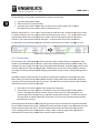
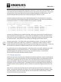
Build the code and run it. Let it run for a few second
seconds and halt the code. Put both of the system timers
in a watch window so you can see their values and not
note what their count is. The 1 second timer count
should always match the 1 millisecond count / 1000. SStart
tart the code again and count out about 5
seconds in your head and then halt the code again – make sure both of the timer values have
incremented as you would expect (you do not have to check them that closely). See Figure 9.4.2.1.
Figure 9.4.2.1: Veri
Verification of 1ms and 1s timers
9.4.3 Sleep Modes
The last thing to do is take advantage of the processor’s ability to power down to save power. Sleep
modes in an embedded system are critical, especially for battery
battery-powered
powered devices where literally every
milliamp (if not microamp) of current that can be saved should be saved. As global energy resources are
used up, engineers will have a growing burden of finding ways to save every ounce of power possible –
you might as well be proactive and start designing w
with power saving in mind. Frankly, wasting power is
stupid.
The ARM7 is quite an old processor, so the power-saving modes available are actually not that great.
More modern processors tend to have additional power savings modes that provide more options on
what parts of the microcontroller
er can stay running. The ARM7 has just two low-power
power states available
as described in section 4.9 of the user guide.
1. Idle mode: core clock is turned off, but peripherals still operate
operate.
2. Power down: the main oscillator is shut down so the core and all peripherals
eripherals are stopped.
Power is still applied to the chip to keep memory, but the chip is not doing any work. An
external signal (like a button press) is required to wake up the processor. You can also use the
real time clock to wake the processor up b
because
ecause it has its own very low power own oscillator
that will keep it running.
The development board will use Idle mode during the main loop to shut down the core and save power
but still allow the peripherals to run. TIMER0 will provide the wake-up signal
al to exit Idle mode and start
another iteration of the main loop. The PCON register holds the bits that select the current power
mode. Setting the IDL bit puts the processor to sleep. When a wake-up
up signal occurs, the IDL bit is
automatically cleared so
o the processor will resume full power operation.
notes_mpgl1_chapter9.docx
Release 1.0
Page 16 of 23
MPG LEVEL 1
Since we want to be able to respond to external interrupts like buttons but still only execute the super
loop every 1ms, we have to add some more logic to manage when the processor continues after it has
reached
eached the end of the main loop. There is a bit defined as _SYSTEM_FLAGS_SLEEP in the Global Global
GGu32SystemFlags that will be set when the processor is supposed to be sleeping. Both
oth the button
interrupts and the TIMER0 interrupt can wake up the processor, but the only function that will be
allowed to clear the sleep bit is the TIMER0 interrupt service routine. If the processor wakes up from a
button press, it will respond to the interrupt but go back to sleep immediately after.
The code looks like this:
/* Sleep the processor -- only TIMER0 can wake the processor back up */
GGu32SystemFlags |= _SYSTEM_FLAGS_SLEEP;
while(GGu32SystemFlags & _SYSTEM_FLAGS_SLEEP)
{
PCON_bit.IDL = 1;
}
main:
Copy the above code and replace this code in ma
/* $$$$ Replace this with sleep mode */
kill_x_cycles(12000);
At last we have everything together for the complete main system timing that will be used for the
remainder of the course. Build the code and make sure it works. Use an oscillosco
oscilloscope
pe to look at the
heartbeat on the red LED and see that it is precisely 1ms and verify that the 1 second timer is still in
sync. As you start to add application code, you can always check the heartbeat to ensure that you see
consistent 1ms periods. If your code breaks the 1ms loop timing rule, you will see the heartbeat signal
start to stretch out so you know you have a problem. Even if that happens, the 1ms counter value will
be accurate because it increments on the FI
FIQ_Interrupt.
9.4.4 IsTimeUp
Since there is only one other TIMER peripheral on the microcontroller and it is very likely that a bunch of
different events and processess will need timing capability, let us write a utility function that provides an
easy way to quickly check if a certain amount of time has passed without using
ng any additional timer
resources.. Since this function is not targeted at any particular application, we will use a “utilities”
source file for the code. In the future, other generic functions can be added to these files as well.
The function is called IsTimeUp() and returns a Boolean answer to tell the system if a certain amount of
time has elapsed or not. The premise is simple: all you need iiss a static variable (or Local Global / Global
Global variable) to capture the current system time when you want to start timing an event. IsTimeUp()
takes arguments of which timer you are using (1ms or 1s), the starting time value, the period of time
you want to track, and an option of whether or not you want to update your saved time (if you
continually wanted to time a certain period, you might want to do this; if you wanted to check if
multiple intervals had passed, you may not want to do this). Since the functionality can be used at any
arbitrary time, it handles rollover of the system reference timer so even if you call the function on day
49 using the 1ms timer (that will roll after 49 days) and you want to time 2 days, the function will
behave correctly.
notes_mpgl1_chapter9.docx
Release 1.0
Page 17 of 23
MPG LEVEL 1
Check out the code in utilities.c to understand the usage of the function – it will likely come in handy in
some future applications you write. The button application that will be written in the next section will
make use of IsTimeUp() to help with button debouncing.
9.5 Button Application
All of the services are ready to let us build a button application that can be used for the remainder of the
course firmware. Just like the LED API that was defined in Chapter 8, we will write a button API and the
associated functions to provide key services for the buttons. The button app will be a bit more involved
than the LED application, and will make use of many of the concepts and tools you have learned in the
last two chapters.
If you are wondering what sort of services are required beyond what the button interrupts provide, take
a moment to consider what additional features would be handy.
1. Debouncing – how are you going to time out a debounce period and verify that a button has
been pressed or released?
2. Button held – the ISR tells you when a button is first pressed, but what if you need to determine
if the button is being held down? What if you have special (secret?) functionality that only
works if a button is held for 10 seconds or some other period of time?
3. Button history – if you have a long state in your program or just a really fast button press, it
would be nice to be able to check if a button had been pressed even if it is no longer pressed.
While you can manage a lot of those features directly with flag bits, timers and various polling
techniques, having an application running that automatically handles all of that is infinitely beneficial
(try writing code for a project where you are managing the buttons manually and you will quickly see!).
It would also be nice to write a fairly generic and modular button application that could be ported to
other systems in the future.
9.5.1 ButtonConfigType
Parameters of buttons are very much like parameters of LEDs. Buttons are at various GPIO locations and
could be either active high or active low. For now we will assume that they are all on the same port,
though they could be at any bit location. It is also assumed that all buttons are interrupt sources. At
any given time, a button could be pressed or released, and we want to be able to time how long a
button is held for. So to start off, we will create a structure type in buttons.h that will hold all of the
information necessary for a particular button.
typedef struct
{
u32 u32Location;
DeviceActiveType eActiveState;
u32 u32IntFlagLocation;
ButtonStateType eCurrentState;
ButtonStateType eNewState;
u32 u32HoldTimeStart;
} ButtonConfigType;
notes_mpgl1_chapter9.docx
/*
/*
/*
/*
/*
/*
Bit location of the button on Port 0 */
Active-high or active-low */
Bit location of the button's interrupt flag */
Current state (RELEASED/PRESSED) of the button */
New state of the button after a debounce period */
Time stamp of the button press */
Release 1.0
Page 18 of 23
MPG LEVEL 1
Not only does ButtonConfigType hold configuration information, it also holds status information. Using
a struct like this allows all the data to be passed in function calls with just a single pointer. The intent is
that each button in the system will have an instance of ButtonConfigType to keep track of it. The
typedef for ButtonStateType used as part of ButtonConfigType is in button.h as well.
The button application will setup an array of ButtonConfigTypes for all of the buttons in the system.
Since the information will be needed throughout the button application code, the array itself will be a
Local Global in buttons.c. It is easiest to initialize the array when it is defined.
/* Button configuration for the current board. */
ButtonConfigType LGasButtons[TOTAL_BUTTONS] =
/*
PIN
HIGH/LOW
EINT#
{ {P0_16_BUTTON0, ACTIVE_LOW, (u32)1 << VIC_EINT0,
{P0_14_BUTTON1, ACTIVE_LOW, (u32)1 << VIC_EINT1,
{P0_15_BUTTON2, ACTIVE_LOW, (u32)1 << VIC_EINT2,
{P0_30_BUTTON3, ACTIVE_LOW, (u32)1 << VIC_EINT3,
};
CURRENT
RELEASED,
RELEASED,
RELEASED,
RELEASED,
NEW
RELEASED,
RELEASED,
RELEASED,
RELEASED,
HOLD START */
0},
0},
0},
0}
Comments in the definition tell you what each field is referring to, and the code is formatted to be as
clear as possible to anyone looking at it. You will often see code where the author has made obvious
effort to be clear either by adding special comments or adjusting formatting and white space to make
the code look better. Clarity like this is an essential part of being a great firmware author!
Note the syntax (u32)1 << VIC_EINTx used to write the EINTx bit location. The constant VIC_ENITx is
literally the bit number of an EINTx bit (i.e. EINT0 is 14). So taking the number 1 (which is a 32-bit
number with bit 0 set) and shifting it left 14 times gives a 32 bit number with only bit 14 set. You will see
this notation more frequently in IAR documentation and in some of the course source code.
To provide quick access to determining when a new button press has occurred, a Boolean array called
LGabButtonNewPress is also defined in buttons.c. This information could have been added to
ButtonConfigType, but was kept as its own array (for no particular reason). It is initialized in
ButtonInitialize() along with GGabButtonDebounceActive.
9.5.2 Button Operation
We know all the services that we want to provide with the button application, now we must design the
firmware to do it. Since this code will be one of the foundational drivers of the development board, we
want to have a good design that not only works, but is also efficient and consumes as little memory
resources as possible. Any piece of firmware you write should be carefully designed and thought out
long before you ever start writing code. That design process has already begun with the definition of
the data structures that the application will use, so now we implement the algorithm that will use the
data.
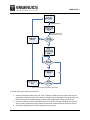
Figure 9.5.2.1 is a flow chart that shows how the button application will work for each button in the
system. The code that implements this system is all in the function ButtonUpdate() in buttons.c along
with some updates in each of the button ISRs that you will need to add. ButtonUpdate() is called in
main on each iteration of the system loop.
notes_mpgl1_chapter9.docx
Release 1.0
Page 19 of 23
MPG LEVEL 1
Figure 9.5.2.1: Button application flow chart
In words, the button system works like this:
1. Assume that buttons always start off. Even if a button is held when the system starts up, the
application will work as soon as the button is released and pressed again. During this time, the
button interrupts are enabled waiting to see the falling edge when a button press occurs.
2. As soon as a button is pressed and the interrupt occurs, the interrupt is disabled so bouncing
does not cause multiple interrupts and the system time is captured for the particular button.
3. The button application waits for the debounce time to expire.
notes_mpgl1_chapter9.docx
Release 1.0
Page 20 of 23
MPG LEVEL 1
4. The state of the button is checked again by reading the GPIO line associated with the button. If
it is still low after the debounce time, then we conclude that a valid button press has occurred.
The button state is changed in memory so we know it is currently pressed, the current system
sys
time is logged so we know when th
the button press started, and the Boolean flag to indicate a
new button press has occurred is set. If the button state is high, that means it was not a valid
button press, so we go back to state 1.
5. The button application then polls the button every cycl
cycle to ensure that it is still pressed. The
particular button’ss interrupt is also still off at this time. As long as the button state does not
no
change, then this state is held.
6. If a pressed button iss released, then a new button debounce period is st
started.
7. When the debounce period has expired, the state of the button is checked. If it has truly been
released, then the state of the button is changed, the interrupt is re-enabled,
enabled, and we return to
state 1. Otherwise, the system returns to polling the button waiting for it to be released.
When there are no buttons pressed, the button application code executes quite quickly.
quickly As more
buttons get pressed, the application will need to do more work to monitor all of the buttons, though it is
still relatively
tively efficient in the way it is coded. The whole purpose of using an array to maintain all of the
button information was to minimize
inimize the amount of code that had to be written to check each button.
The same code is used to check each button with the var
varying
ying information managed with a loop index.
There are many ways that the button application could be written, and tthis
his design has advantages and
disadvantages. For the purpose of this chapter, you should be able to compare the flow chart with the
code in ButtonUpdate() and be comfortable with the way it works. The part left for you to write are the
updates that take place in each of the button interrupt service routines.
Add three lines of code to each button ISR to finish the button application:
1. Disable the interrupt
2. Set the button’ss debounce active flag to TRUE
3. Save the currentt 1ms system tick in the button’s data structure so the debounce period for the
button can be tracked.
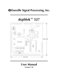
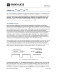
Build and test your code to make sure you see the correct information being updated.. The entire
LGasButtons array of ButtonConfigType da
data
ta structures can be viewed in a watch window. Simple ad
LGasButtons to a watch window and IAR will automatically name and display the array elements. The
only thing you might need to do is change the display type for the Values of certain fields like
u32Location as it will default to decimal display that is not very helpful. One of the benefits of using
enumerated typess for things like ACTIVE_LOW or PRESSED is also shown here values for fields like
eCurrentState are shown in plain English (from the enum definition). Figure 9.5.2.2 shows a snapshot
from the test code.
notes_mpgl1_chapter9.docx
Release 1.0
Page 21 of 23
MPG LEVEL 1
Figure 9.5.2.2: Snapshot of LGasButtons with some of the data fields shown
9.5.3 Button API
Now that the button application is working, API functions must be provided so that other applications
can use the button app. We want a few simple functions:
1. IsButtonPressed(): returns TRUE if a button is currently pressed
2. WasButtonPressed():: returns TRUE if a button was pressed since last time it was checked, even
if the button is no longer pressed at that mome
moment. If so, we need a function to acknowledge
that we have received the informatio
information – ButtonAcknolwedge().
3. IsButtonHeld() – returns TRUE if a button has been held for a certain amount of time.
IsButtonPressed() is already complete and the function declarations and shells for the other three
functions are written for you. It is up to you to implement the other three functions.. They will require
just a few lines of code each. Use existing parameters of the button data structures and return the
correct Boolean value where applicable. You do not need to write any code outside of these
the functions,
but you do need to understand the button flow chart and how button information is stored.
stored Make sure
your code builds without errors. Yo
ou will test your functions in the Chapter Exercise.
notes_mpgl1_chapter9.docx
Release 1.0
Page 22 of 23
MPG LEVEL 1
9.6 Chapter Exercise
The chapter exercise is all about using the button and LED applications to solidify your understanding of
the functionality that is available
lable on the development board at th
this point. As the course progresses, it
will continue to use these functions so you must be comfortable with what
at has been covered up to now
or you will struggle as we continue.
Source files chapter9.c and chapter9.h are already included in the project. The initialization function is
written for you, but you will need to add calls in main
main.c to run the initialization function and the
chapter9 application itself. Only the Idle state is necessary and the framework is already in place for
you. Add and test
est the following functionality – do one piece at a time and ensure it is working correctly
before moving on:
1. BUTTON0 thru BUTTON3 correspond to WHITE, PURPLE, BLUE, CYAN LEDs -- when the button is
pressed, the corresponding LED is lit.
2. If BUTTON0 is held for 3 seconds or more, the green LED will turn on and stay on until BUTTON0
is released.
3. When button 1 is pressed, the yellow LED starts to blink at 4Hz. If pressed again, the yellow LED
stops blinking.
BUTTON2 cycles the yellow LED blink rate between 1Hz, 2Hz, 4Hz and 8Hz but only
onl when the
LED is currently on.
4. BUTTON3 toggles the heartbeat LED output on and off.
notes_mpgl1_chapter9.docx
Release 1.0
Page 23 of 23