1
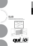
user ma nu al QK-CE220RL V02 CONTROL BOARD FOR A 230V ac SINGLE-PHASE MOTOR 230V 433,92 MHz PLUG & PLAY CONTENTS INTRODUCTION 3 MAIN FEATURES OF THE CONTROL BOARD 3 TECHNICAL DATA 3 INSTALLATION 3 LAYOUT AND CONNECTIONS FOR SLIDING GATES 4 LAYOUT AND CONNECTIONS FOR GARAGE DOORS 5 OTHER SETTINGS 6 RADIO-RECEIVER SETUP 6 SETUP 7 FINAL TESTING 8 TROUBLESHOOTING 8 DECLARATION OF COMPLIANCE 9 ® QUIKO GUARANTEE: GENERAL CONDITIONS 10 INTRODUCTION This manual is enclosed with control unit QK-CE220RL and may not be used for different products. Moreover it has been especially written for use by qualified fitters. Important note: disconnect the panel before operating on the control unit. QK-CE220RL control unit has been designed to control electromechanical gear motors such as slide gates. Any other use is considered improper and is consequently forbidden by current laws. The automation system you are going to install is classified as “machine construction” and is therefore included in the application of European directive 89/392 EEC (Machinery Directive). The above mentioned directive includes following prescriptions: only trained and qualified personnel should install the equipment; the installer must first make a “risk analysis” of the machine; the equipment must be installed in compliance with the regulations in force; after installation, the machine owner must be given the “declaration of compliance”. Borinato F.lli Snc observes all security standards in any phase of the product’s production process (see the attached declaration of compliance) and the installer must therefore observe the same standards when installing the system. Should he ignore such regulations, he will be fully responsible for any damage caused by the system. For this reason we suggest to read all instructions in this manual in advance. MAIN FEATURES OF THE CONTROL BOARD - Motor torque adjustment Built-in flashing light circuit with opening (fast) / closing (slow) / pause (always on) differentiated flashing Built-in radio receiver with 100 memories (one channel) Input status LEDs Protection fuses 2nd “pedestrian entry” function by key selector / wall mount switch Soft start/stop function Plug and play technology TECHNICAL FEATURES Power Maximum power Line fuse 230V ac 50/60 Hz About 1KW F1 3.15A DELAYED Motor output 230V ac Accessories output 24Vac 500mA Logic circuit input Operating temperature IP protection rate of the enclosure 5Vdc -20°C / +70°C IP 55 INSTALLATION Position the control board as near as possible the gear motor, in order to avoid over long connection cables; Use power cables (power input, motors, earth and flashing light) of at least 1.5 mm2 conductor, taking into consideration the amperage, voltage drop and length. This requirement doesn’t apply to the connection cables of the auxiliary control devices such as key switch and photocell, whose cross-section can reduced to 0,5 mm2; Ensure connections to the terminal board are made not to alter the level of protection offered by the housing, which must be installed in a dry and suitable place according to the IP rating; PLEASE REMEMBER TO PROPERLY EARTH THIS PRODUCT AND TO OBSERVE THE SAFETY REGULATIONS IN FORCE IN THE COUNTRY OF INSTALLATION. 3 ,3" 730#" " (*! 3 33 )3/ *3*3.*3=*!)13 3!3*3*))* 3 *333.*3/) (3=*3 3)3right13 % % D C B @ $% 4 " 0#" % 333333333333333333333333333 8 ,3"#3 3*!3.3 3 # : ; , 0 " " ))3*3* 3 !!3;>+*3?88. 3 !!3;<8+*3)3*43 3:<3F3 .. 43 3:;5:>3. 33*3** )*3)*.3 !!3;<8+* )3/ *3 (3!)3;<8+*3275:893?87@8 *3=:D3*)43;831 :85:: :;5:<5:> :@5:B :B5:C :D5;8 3).3( ) 3).3( D5B 5 5 5 5 5 5 5 5 5 5 5 5 $$$1 &" &" 66 66 66 66 66 ;<8+*A ?8 C5B 3( #33 /! 3 3 *.3 *..3 @5< : ))63#3-33 *3*!E3#355G3 363#355G3..*3 3 33 *3*3!.3 63&355G3*3 3*!3. ;<8+A ?8 ?5< 7) 3(3*3%3( *3 7) 3( *363#3-33 *3*!E3#355G3..*3 3 33*43) 3 3*). 3:8.3 3 )*33 /*)3*3!.3 3! 3 /*)3)*63#355G3..*3 3 33*3*3 !.3 63&355G3!3 3*3*)3*3*3 3*!3. : " $/ #3# T 230Vac :5< ;5< >5< .. #3##"30#" #30#" 33 3"&3 #3##"30#" #" ) '!.33 3"&3 ? $ )3/ *3*!33=3(3 3(33*33. $13 *3!)3)3 * 5$3*!3)3 *3*)3)3 *3*3*)3)3 *33)3 ))3)3 3*)3)3 3).3(3)3 ) 3).3(3)3 03"#3 3 3!)* 3 > < "#$$$ &$ '$ ($ )$ *$ +$ ,$ -$ .$ 0$ $$$$$ 3*3 33*))* 3*333.*3/) (3=*3 3)3left) $se3= 33 )3/ *1E3 53 . 3*/)3 3 3:;3*3:>3 53 3).3(3*/)3 3 3C3*3D333 LD9 24Vac M BREAK TRIMMER for pause time setting RADIO PROG PROG LD2 BREAK POWER OPEN/CLOSE SWITCH KEY SELECTOR Flashing lamp output 230Vac Control board power supply 230Vac +/-10% 50/60Hz Antenna (19 signal, 20 screen) LD1 16-17 17-18 19-20 F Photocells and accessories output 24Vac 500mA Motor output 230Vac single phase, connector 13 = common, connectors 12-14 motor feeding and capacitor LD0 10-11 12-13-14 RADIO PROG button for remotes programming Stop switch F1 6-3 230V\ 50Hz Photocells / safety edge. If excited this contact causes: DURING OPENING --> No effects. DURING CLOSING --> immediate stop of the gate and resume opening. DURING PAUSE --> recharge of pause time OPEN 5-7 230Vac\ 50Hz - N.C. N.C. N.O. N.O. N.C. Type M1 Description - YES YES NO NO YES Bypass if not used? MOTOR Open/close switch and key switch Not used Not used, to be bypassed Jumper PROG for SETUP 1-3 2-3 4-3 PHOTOCELLS / SAFETY EDGE NON USATO NON USATO COM. ST OP FOT. COS COM. STOP SWITCH FLASHING LIGHT 230Vac Connector N° open common NOT USED CLOSE NOT USED CAPACITOR COMMON DIP SWITCH ES for SETUP COMMON close START P. START MEANING Control board status LED (it switches on when the gate is moving) Mains Supply led Radio-receiver status led Start signal led Not used Not used Photocell / safety edge led Stop signal led Not used Not used POWER TRIMMER for force regulation LD8 LD7 LD6 LD5 LD4 LD3 Number of LED LD0 LD1 LD2 LD3 LD4 LD5 LD6 LD7 LD8 LD9 LAYOUT AND CONNECTIONS FOR GARAGE DOORS 5 , " !/ 4(& & 5 5 5 5 5 9: 5 5; Pre-flashing 5 9 ; # 66 !7 $ " 8 $ ++8 " 8 ++8 *$ "8 * ++ 8 = ++ 8 pre-flashing OFF = " 8 pre-flashing ON >? 66 !7 @ 6 B@ 6C 180B REMOTE RECEIVER SETUP (it is necessary to have a remote control which is already memorized in the receiver) ! " # $% ! & ' ( ' ' * ( !'( (( ' ' ( +", - & ! " ' ( ! ! ++ 6 ‐ Enter the ray of action of the receiver with a remote control already memorized and maintain pressed two buttons of the same until the lighting of the flashing lamp. ‐ Press the desired button of the new remote to be memorized. ‐ The flashing lamp flashes to confirm the memorization of the new remote. " > 4(& Point A * ++ # 66 H* ' 5 5 5 5 H $ ++ $ " ' H& I ' H& I J " J " " ++ " ! ( ++ ! ( ! ( & ! ( & ! ( ! !(&7 & ' ! & ! Point B ! ( ' & & !(&7 FORSLIDINGGATESONLY: INCASEOFSTRONGINERTIAOFTHEGATE YOUCANACTIVATEMOTORBRAKE FUNCTIONBYSETTINGDIP4TOON DURINGSETUP.DIP2MUSTBESETTLEDTOOFF & ! ( ! !(&7 & & & !(&7 ! ( ' & ' ! & ! ! ( ! !(&7 ! ! ( ! !(&7 ! & 4(& +", Important notice about slow down function on sliding gates (to be used if slow down goes wrong at point B) If the power of slow down is not adequate and the gate doesn't move smoothly during slow down, you may regulate the power of slow down by means of the following steps: 7 --1) unplug the board from mains power supply and plug it again --2) close PROG jumper --3) set DIP3 to ON --4) set POWER TRIMMER to the minimum --5) close the gate manually --6) set DIP1 to OFF --7) set DIP2 to ON --8) press TX once --9) gate starts moving --10) press TX once --11) gate starts slow down --12) adjust the power of slow down by means of POWER TRIMMER until the gate reaches a smooth movement --13) press TX once to save the configuration of slow down --14) restart setup from point A FINAL TESTING Once all connections have been done, check that LEDs status is as follows: LED STATUS TABLE FOR SLIDING GATES When the automation is opened When the automation is closed When the automation is stopped on the middle of opening OFF ON OFF OFF OFF ON ON ON OFF ON OFF ON OFF OFF OFF ON ON ON ON OFF OFF ON OFF OFF OFF ON ON ON ON ON LD0 LD1 LD2 LD3 LD4 LD5 LD6 LD7 LD8 LD9 LED STATUS TABLE FOR GARAGE DOORS When the automation is opened When the automation is closed When the automation is stopped on the middle of opening OFF ON OFF OFF OFF ON ON ON OFF OFF OFF ON OFF OFF OFF ON ON ON OFF OFF OFF ON OFF OFF OFF ON ON ON OFF OFF LD0 LD1 LD2 LD3 LD4 LD5 LD6 LD7 LD8 LD9 TROUBLESHOOTING Problem The LD1 led isn't switched ON so the control board isn't supplied with electricity Solution F1 fuse has blown or it has not been inserted properly. Please check 230Vac (connectors 17 and 18) aren't connected. Please check. Check the led status as per described within TESTING paragraph A START command doesn't let the automation start Memorise again the transmitter button on the radio receiver or check key selector connections Check that POWER TRIMMER is settled at least at the 2/3 of regulation Reverse M1 motor cables to reverse the sense of rotation of the motor A START command let the flashing light start but doesn't Check M1 motor connections let the automation start The remote cannot be memorised on the receiver 8 Check that the 12Vdc common isn' t connected with the 24Vac Take the antenna cables off and try again. Change the battery of the transmitter and try again. QUIKO® GUARANTEE: GENERAL CONDITIONS Quiko® products’ guarantee lasts 24 months from the date of purchase of the products (as proved by the sale document, receipt or invoice, which must be attached to this guarantee). This guarantee covers the repair with free replacement (ex-works Borinato F.lli Snc: packing and transport at the customer’s expense) of parts that Borinato F.lli Snc recognises as being faulty with regard to workmanship or material. For home-interventions, also during the guarantee period, a “call-out fee” will be charged for travelling expenses and labour costs. The guarantee does not cover the following cases: v if the fault was caused by an installation that was not performed according to the instructions provided by the company inside the product pack; v if original Quiko® spare parts were not used to install the product; v if the damage was caused by an Act of God, tampering, overvoltage, incorrect power supply, improper repairs, incorrect installation, or other reasons that do not depend on Quiko®; v if a specialised maintenance man does not carry out routine maintenance operations according to the instructions provided by the company inside the product pack. The repair or replacement of pieces under guarantee does not extend the guarantee period. 10 11 1095 Budapest, Mester u. 34. Tel.: *218-5542, 215-9771, 215-7550, 216-7017, 216-7018 Fax: 218-5542 Mobil: 30 940-1970, 20 949-2688 1141 Budapest, Fogarasi út 77. Tel.: *220-7940, 220-7814, 220-7959, 220-8881, 364-3428 Fax: 220-7940 Mobil: 30 531-5454, 30 939-9989 E-mail: [email protected] Web: www.delton.hu www.kaputnyitunk.hu The Manufacturer can technically improve the quality of its products without any prior notice. Il Fabbricante può apportare ai suoi prodotti della qualità, senza preavviso.