1
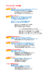
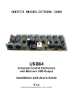
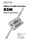
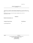
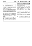
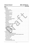
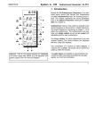
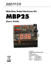
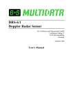
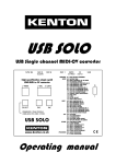
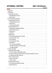
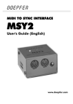
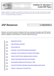
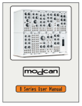
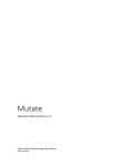
DOEPFER
Ribbon To Midi Controller
R2M
User’s Guide
© 2005 by
Doepfer Musikelektronik GmbH
Geigerstr. 13
82166 Graefelfing
Germany
Phone:
#49 89 89809510
Fax:
#49 89 89809511
Web Site: www.doepfer.de
Email: [email protected]
OPERATING AND SAFETY INSTRUCTIONS
Please follow the given instructions for use of the instrument because this will
guarantee correct instrument operation. Due to the fact that these instructions touch
on Product Liability, it is absolutely imperative that they be read carefully. Any claim
for defect will be rejected if one or more of the items was observed. Disregard of the
instructions can endanger warranty.
•
•
•
•
•
•
•
•
•
•
•
•
•
•
The instrument may only be used for the purpose described in this operating
manual. Due to safety reasons, the instrument must never be used for other
purposes not described in this manual. If you are not sure about the intended
purpose of the instrument please contact an expert.
The instrument has to be shipped only in the original packaging. Any instruments
shipped to us for return, exchange, warranty repair, update or examination must
be in their original packaging! Any other deliveries will be rejected. Therefore, you
should keep the original packaging and the technical documentation.
The instrument may only be operated with the voltage written on the power input
on the rear panel. Before opening the case disconnect the power plug.
Every modification has to be carried out only at the manufacturer or an authorized
service company. Any modification not released by the manufacturer leads to the
extinction of the operation permission.
With the introduction of a third person the warranty will be lost. In case of a
destroyed warranty seal, any warranty claim will be rejected.
The instrument must never be operated outdoors but only in dry, closed rooms.
Never use the instrument in a humid or wet environment nor near inflammables.
No liquids or conducting materials must get into the instrument. If this should
happen the instrument must be disconnected from power immediately and be
examined, cleaned and eventually be repaired by a qualified person.
Never subject the instrument to temperatures above +50°C or below -10°C.
Before operation the instrument should have a temperature of at least 10°C. Do
not place the instrument into direct sun light. Do not install the instrument near
heat sources.
Keep the top side of the instrument free in order to guarantee proper ventilation,
otherwise the instrument could be overheated. Never place heavy objects on the
instrument.
All cables connected with the instrument must be checked periodically. If there is
any damage the cables must be repaired or replaced by an authorized person.
Transport the instrument carefully, never let it fall or overturn. Make sure that
during transport and in use the instrument has a proper stand and does not fall,
slip or turn over because persons could be injured.
Never use the instrument in the immediate proximity of interfering electronic
devices (e.g. monitors, computers) since this could create disturbances within the
instrument and corrupt memory data.
The exchange of electronic parts (e.g. EPROMs for software update) is allowed
only if the instrument is disconnected from power supply.
When using the instrument in Germany, the appropriate VDE standards must be
followed. The following standards are of special importance: DIN VDE 0100 (Teil
300/11.85, Teil 410/11.83, Teil 481/10.87), DIN VDE 0532 (Teil 1/03.82), DIN
VDE 0550 (Teil 1/12.69), DIN VDE 0551 (05.72), DIN VDE 0551e (06.75), DIN
VDE 0700 (Teil 1/02.81, Teil 207/10.82), DIN VDE 0711 (Teil 500/10.89), DIN
VDE 0860 (05.89), DIN VDE 0869 (01.85). VDE papers can be obtained from the
VDE-Verlag GmbH, Berlin.
Page 2
R2M User's Guide V1.11
Contents
Introduction ..................................................................................................................4
Connections .................................................................................................................5
n Power Supply (9V DC 250 mA) ...........................................................................5
o Manual connector (Ribbon Contr.) ......................................................................5
r CV1 Out...............................................................................................................6
q CV2 Out...............................................................................................................6
p GATE OUT ..........................................................................................................6
s MIDI Out ..............................................................................................................6
t MIDI IN ................................................................................................................6
Operation .....................................................................................................................7
Controls.....................................................................................................................7
Fundamental operation notes ...................................................................................8
Menu / parameter overview ......................................................................................9
Description of menus and parameters ....................................................................10
Menu 1: CV parameter ........................................................................................10
1-1 Trigger polarity [1] ......................................................................................10
1-2 Direction [1] ................................................................................................10
1-3 Direction [2] ................................................................................................10
Menu 2: Midi event ..............................................................................................11
2-1 Midi event [1]..............................................................................................11
2-2 Midi event [2]..............................................................................................13
Menu 3: Midi parameter.......................................................................................14
3-1 Midi channel [1] ..........................................................................................14
3-2 Note / controller number [1]........................................................................14
3-3 Controller number [2] .................................................................................14
3-4 Pitch scale [2].............................................................................................14
Menu 4: Mode......................................................................................................15
4-1 Quantization ...............................................................................................15
4-2 Number octave...........................................................................................16
4-3 Retrigger time.............................................................................................16
4-4 Transpose offset ........................................................................................16
Menu 5: Arpeggio ................................................................................................17
5-1 Mode ..........................................................................................................17
5-2 Octave........................................................................................................18
5-3 Sync ...........................................................................................................18
5-4 Gate length.................................................................................................18
5-5 Norm CV ....................................................................................................19
Menu 6: Start/Stop (arpeggio) .............................................................................19
Preset / Store.......................................................................................................20
Typical applications ................................................................................................21
Generating a quantized pitch control via Midi and CV/Gate................................21
Generating note messages only (no pitch bend).................................................23
Generating single note messages with pitch bend (Trautonium mode) ..............23
Generating succeeding note messages with pitch bend .....................................24
Generation of the control voltages CV1/CV2 and Gate.......................................26
Appendix ....................................................................................................................28
R2M User's Guide V1.11
Page 3
Introduction
R2M is a so-called ribbon controller that generates control signals by moving the
finger on the ribbon manual. The output signals are generated as Midi and CV/Gate
control voltages simultaneously. Consequently R2M allows to control both Midi and
CV/Gate based equipment (e.g. analog synthesizers or analog modular systems).
R2M is the abbreviation of Ribbon to Midi.
R2M is made of two parts: the manual and the control box.
The manual is made of a 50 cm long linear position sensor and a pressure
sensor that is located below the position sensor. Touching the sensor with the finger
generates a voltage that is proportional to the position of the finger. In principle the
position sensor works like a 50 cm long fader (i.e. slide potentiometer). The slider is
represented by the finger. As soon as the finger touches the position sensor the
slider contact is closed and the finger position represents the slider position. If the
finger is removed the slider is removed too (i.e. the slider contact open).
Additionally a pressure voltage is generated that increases with the pressure applied
to the position sensor. Both voltages are fed to the R2M control box via a four-pin
cable (same as USB but does not transmit USB data). For the manual the same type
as the for the modular version A-198 is used.
Fig. 1
The control box contains two analog-to-digital converters and a microcontroller. It
converts the data coming from the manual (finger position and pressure) into the
corresponding Midi data resp. CV/Gate voltages. The Midi input is used to transpose
the notes generated by the R2M or to control the R2M arpeggiator functions. The
programming of the device is carried out with a LC display, 10 buttons and 6 LEDs.
The control box is available even without manual to make use of an already existing
A-198 manual and take advantage of the additional features of the R2M control unit
compared to the comparatively simple A-198.
Remark: To detect if the finger touches the position sensor the slider contact is pulled
high if the finger is removed. This corresponds to the rightmost point of the position
sensor. This has no influence on to the general operation of R2M but the last few
millimeters at the right rim of the manual cannot be used – i.e. moving the finger
within a few millimeters in the rightmost position has no effect.
Page 4
R2M User's Guide V1.11
Connections
MIDI IN
t
MIDI OUT
s
Gate CV2 CV1
OUT OUT OUT
r q p
Ribbon
Contr.
9V DC
250mA
o
n
Fig. 2
n Power Supply (9V DC 250 mA)
R2M does not have a built-in power supply. Instead it uses a plug-in type external
power supply (AC adapter). One reason for this feature is electrical safety. Keeping
danger voltages (mains) out of the R2M increases the electrical safety. Another
reason for the external power supply is the fact that line voltages and plug types vary
considerably from country to country. Using a plug-in external supply the R2M can be
used anywhere with a locally purchased power supply, thus keeping the retail price
down.
In Germany a VDE approved power supply is included with the R2M. In other
countries a power supply with suitable mains voltage and mains connector has to be
purchased separately by the user provided that the dealer resp. representative does
not enclose the power suppy. The power supply must be able to deliver 7-12 VDC
unstabilized voltage, as well as a minimum current of 250mA. The correct polarity of
the DC voltage connector is: outside ring = GND, inside lead = +7...12V. An external
power supply of high quality and safety should be used.
The R2M is switched ON by plugging the AC adapter into a wall outlet and
connecting it to the appropriate jack of the R2M. There is no separate ON/OFF
switch. If the polarity of the power supply is incorrect, the R2M will not function.
However, there is no danger of damage to the circuitry since it is protected by a
diode.
o Manual connector (Ribbon Contr.)
The manual is connected to the control box with the 4-pin cable that is included.
1
Even though the same type of connector as for USB is used it is not
allowed to connect the control box or the manual to any USB device!
Both the USB device and the controller or manual will be damaged !
In this case the warranty will be void ! We will not compensate any
damage caused by ignoring this direction for use.
R2M User's Guide V1.11
Page 5
r CV1 Out
This socket outputs an analog control voltage in the range 0...+5V that depends on
the position of the finger. It is normally used to control the pitch of analog equipment
(e.g. pitch on an analog synthesizer or VCO). The CV1 output follows the 1V/octave
standard (relevant only in the quantized modes).
q CV2 Out
This socket outputs an analog control voltage in the range 0...+5V that depends on
the pressure applied to the manual. It can be used to control any other voltage
controlled parameter of an analog synthesizer (e.g. loudness, filter frequency,
modulation depth, LFO frequency, panning).
p GATE OUT
This socket outputs a gate signal with +5V level. Normally the gate output is 0V in the
off state and +5V in the on state. The gate is determined by the finger touch. As soon
as the finger touches the position sensor the gate turns on. If the finger is removed
the gate output turns off. Positive or negative polarity can be chosen, i.e. if the gate
output turns to +5V or 0V if the finger touches the position sensor. Normally the gate
output is used to trigger the envelope generator (ADSR) of the analog synthesizer
controlled by the R2M.
Even switched trigger or "S-trig" based equipment can be controlled (e.g. most of the
Moog and Arp devices) by removing a jumper inside the R2M control box. The pin
header for the jumper is labelled JP3 and is located just behind the gate socket. Keep
the jumper to be able to undo the S-trig modification.
Pay attention if you open and close the R2M case. Use a suitable screw driver only
and open/close the case very carefully. We cannot take back units with damaged
cases (e.g. scratches caused by the screw driver). Even the warranty will be lost if
any modification except the removal or installation of the jumper is carried out. If you
are not sure whether you are able to carry out the jumper removal/installation please
send the unit to your local dealer/representative.
s MIDI Out
Connect the Midi Out socket of R2M with the Midi In socket of the device to be
controlled by the R2M (e.g. computer with Midi, Synthesizer, Expander, Sequencer)
via a suitable MIDI-cable. If only analog equipment is controlled via CV/gate the Midi
output is left unconnected.
t MIDI IN
If you want to transpose the note messages generated by the R2M or make use of
the R2M arpeggiator functions the Midi In socket of the R2M is connected to the Midi
Out socket of the Midi device that generates the note on/off and clock messages
required for these features (see below).
If the arpeggiator of the R2M is off the incoming Midi data with the same Midi channel
as the R2M are merged to the data generated by the R2M (so-called channel voice
messages, e.g. note on/off, control change, pitch bend, program change). Refer to
chapter 3-1 concerning the currently selected R2M Midi channel.
Page 6
R2M User's Guide V1.11
This function can be used to modify Midi data with the R2M (e.g. adding pitch bend to
note messages on the same Midi channel).
If the arpeggiator is on the Midi merging function is not working. Incoming data on
other Midi channels than the currently selected R2M Midi channel are not merged !
The Midi input of R2M is not suitable for large amounts of Midi data (e.g. SysEx
strings or Midi messages coming from an computer sequencer) but only for small
data rates, e.g. the note on/off messages of a controlling keyboard. In case of large
amounts of incoming Midi messages data loss or delay may occur. Same applies for
Midi messages that do not match the R2M Midi channel.
If the transpose function, the arpeggiator or the merging of R2M Midi data to
incoming channel voice messages is not used the Midi Input of the R2M is left open.
Operation
R2M is switched on by plugging the AC adapter into a wall outlet and connecting it to
the appropriate power supply socket n. There is no separate ON/OFF switch.
c
e
f
d
Fig. 3
After power on the six LEDs (2) will light up for a short time and the display (1) shows
the software version. Otherwise the AC adapter used is not suitable, has the wrong
polarity or does not work.
Controls
c
d
e
f
LC display: 2 x 16 characters with backlight, displays the R2M parameters
Menu buttons with corresponding LEDs, used to select/display a menu
Preset Get / Store buttons, used to store/call up a preset
Up / down buttons, used to increase/decrease values
The up/down buttons are accelerated, i.e. the increase/decrease speed becomes
higher as the button the held down.
R2M User's Guide V1.11
Page 7
Fundamental operation notes
•
•
•
•
R2M contains a lot of parameters that can be adjusted by the user and stored in
16 presets. Similar parameters are collected in the same menu.
A menu is activated by pressing the corresponding menu button. The active menu
is indicated by an illuminated LED.
Repeated pressing of the same menu button leads to the next parameter that can
be displayed and adjusted in this menu. The process is circular, i.e. after the last
parameter the first parameter of this menu appears again.
To exit a menu another menu button has to be pressed.
Fig. 4 shows the information that is displayed in the LCD.
a
c
b
4|Midi Param. [1]
4|Pitchscale:
d
e
63
f
Fig. 4
a
b
c
d
e
f
number of parameters available in the currently selected menu
name of the menu
the sensor resp. the CV output that refers to the currently selected parameter (1
= position sensor, 2 = pressure sensor)
number of the currently selected parameter
name of the parameter
current value of the parameter, that can be changed with the up/down buttons
Page 8
R2M User's Guide V1.11
Menu / parameter overview
Menu 1 CV Parameter
Index
1
2
3
Parameter
Trigger Pol.
Direction
Direction
Sensor
1
1
2
Range
0 to 1
0 to 1
0 to 1
Default
0
0
0
Explanation see chapter ...
1-1 Trigger polarity [1]
1-2 Direction [1]
1-3 Direction [2]
Page
10
10
10
Default
note
off
Explanation see chapter ...
2-1 Midi event [1]
2-2 Midi event [2]
Page
11
13
Menu 2 Midi Event
Index Parameter
1
2
Sensor Range
1
a) to h) 1)
2
a) to f) 2)
1)
a) - h) :
off, note, note&pitch relative, note&pitch absolute, pitch, control change, after touch, program Change
2)
a) - f) : off, pitch+, pitch-, control change, after touch, program change
Menu 3 Midi Parameter
Index Parameter
Sensor Range
1
Midi channel
1&2
1 to 16
2
Note/ctrl no
1
0 to 127
3
4
ctrl no
pitch scale
Default
1
36
Explanation see chapter ...
3-1 Midi channel [1]
3-2 Note / controller
Page
14
14
2
2
0 to 127
0 to 127
1
63
number [1]
3-3 Controller number [2] 14
14
3-4 Pitch scale [2]
Sensor
1
1
1
1
Range
12 tone
1 to 5
0 to 100
0 to -96
Default
12 tone 3)
3
1
00
Explanation see chapter ...
4-1 Quantization
4-2 Number octave
4-3 Retrigger time
4-4 Transpose offset
Page
15
16
16
16
Range
a) to d) 4)
1 to 5
a) to c) 5)
1 to 127
0 to -96
Default
OFF
1
Int BPM
12
36
Explanation see chapter ...
5-1 Mode
5-2 Octave
5-3 Sync
5-4 Gate length
5-5 Norm CV
Page
17
18
18
18
19
Menu 4 Mode
Index
1
2
3
4
3)
Parameter
Quantisierung
Number octave
Retrigger time
Transpose
offset
12Tone , Major, ….. MinorChord7
Menu 5 Arpeggiator
Index
1
2
3
4
5
4)
5)
Parameter
Mode
Octave
Sync
Gate length
Norm CV
Sensor
1
1
1
1
1
off, note on/offf, note hold, note write
external, internal BPM , Mod&BPM
sensor 1 = position sensor; sensor 2 = pressure sensor
R2M User's Guide V1.11
Page 9
Description of menus and parameters
Some parameters have an interdependence or cannot be explained without the
function of another parameters. Consequently it is sometimes unavoidable to refer to
a parameter that may be described in another menu that may follow later. In the
chapter Typical applications on page 21 some standard examples of the R2M are
described.
Please put the manual in front of you with the connector that leads to the control box
on the right side.
Menu 1: CV parameter
number of parameters: 3
This menu contains all parameters that refer to the analog control voltages CV1 and
CV2 generated by the R2M.
1-1 Trigger polarity [1]
Range: 0 , 1
This parameter refers to the function of the gate output.
0
→
+5V →
+5 V when the position sensor is touched
0 V when the position sensor is released
1 / inverted: +5V →
0V →
0 V when the position sensor is touched
+5 V when the position sensor is released
0 / normal:
Remark 1: If the device connected to the gate output behaves reverse the trigger
polarity has to be changed.
Remark 2: If a device with switched trigger (S-Trig) is controlled by the R2M the
inverted gate mode has to be selected and the hardware modification for switched
trigger described in the attachment has to be carried out (removing a jumper inside
the R2M).
1-2 Direction [1]
Range: 0 , 1
This parameter refers to the coherence between the movement of the finger that
touches the position sensor and the resulting Midi message resp. control voltage
CV1.
0 / normal: Moving the finger to the right causes an increasing control voltage CV1
1 / inverted: Moving the finger to the right causes a decreasing control voltage CV1
1-3 Direction [2]
Range: 0 , 1
This parameter refers to the coherence between the pressure applied to the manual
and the resulting Midi message resp. control voltage CV2.
0 / normal: Increasing pressure causes an increasing control voltage CV2
1 / inverted: Increasing pressure causes a decreasing control voltage CV2
Page 10
R2M User's Guide V1.11
Menu 2: Midi event
number of parameters: 2
This menu contains all parameters that refer to Midi messages assigned to the
position and pressure sensor.
2-1 Midi event [1]
Range: a - h
This parameter refers to the Midi message assigned to the position sensor [1]. It has
also an influence to the function of the CV1 and gate outputs.
a
b
c
d
e
f
g
h
Off
Note
Note & pitch bend relative
Note & pitch bend absolute
Pitch & FixNote
Control change
After touch
Program change
The Midi messages and the analog voltage CV1 are generated simultaneously.
a
Off
In this case no Midi messages, no CV1 and no gate is generated.
Modes b, c and d are used to generate note on/off events and the corresponding
analog signals CV1 and gate. One of these three selections is normally used for the
position sensor. The generated Midi and CV/gate signals are influenced by these
parameters too:
3-2 Note number
3-3 Controller number
3-4 Pitch scale
4-1 Quantization
4-2 Number octave
4-3 Retrigger time
The combination of all parameters determines how the Midi and CV/gate data are
generated. In the chapter system functions (page 21) the interaction of all
parameters is explained in detail.
b
Note
Touching the position sensor generates a Midi note on message and the
corresponding pitch control voltage CV1. The gate output turns on. The note number
and the value of CV1 depends upon the position of the finger.
Releasing the finger without moving the finger generates the corresponding Midi note
off message and the gate output turns off.
If the finger moves over the position sensor without releasing the finger the result
depends upon the current setting of the retrigger value 4-3. If this value is zero no
new Midi note or CV1/gate is generated as the finger glides over the manual. If the
retrigger value 4-3 is not zero the behaviour is different: As soon as the finger
reaches a position that corresponds to another note a Midi note off message for the
"old" note is generated and the gate output turns off. After the retrigger time 4-3 that
is measured in milliseconds the new note on message is generated. Simultaneously
the corresponding CV1 is generated and the gate output turns on. If the analog
synthesizer resp. the envelope generator (ADSR) connected to the gate output of
R2M User's Guide V1.11
Page 11
R2M does not recognize the gate on/off/on transition the retrigger time 4-3 has to be
increased until the gate transition is recognized by the receiver. The Midi messages
are sent on the Midi channel adjusted in menu 3-1.
Only in this mode b the quantization (see 4-1) is active.
c
Note & pitch relative
In this mode pitch bend data are generated in addition to the note on message of
mode b as the finger glides over the position sensor without releasing the finger.
Touching the position sensor generates a Midi note on message and the
corresponding pitch control voltage CV1 (so far the same as mode a). If the finger
glides over the position sensor without releasing the finger only pitch bend data are
generated after the initial note on message. If the finger is released a note off
message is generated. To generate another note on message the position sensor
has to be touched again.
The pitch bend data depend upon the position difference between the starting point
and the current position of the finger, and the value of the pitch scale 3-4. Pay
attention that the pitch scale has to correspond to the setting of the pitch scale of the
receiver (for details refer to 3-4). The retrigger time 4-3 has no meaning in this mode.
The Midi messages are sent on the Midi channel adjusted in menu 3-1.
This is what we call the "Trautonium mode" as this is just the behaviour of the
Trautonium invented by Mr Trautwein early in the 19th century. For details about the
Trautonium please refer to our web site www.doepfer.com.
d
Note & pitch absolute
This mode is a combination of the modes b and c. Touching the position sensor
generates a Midi note on message and the corresponding pitch control voltage CV1
(so far the same as mode a and b). If the finger position does not correspond exactly
to a semitone resp. Midi note (normally this will be true) a "pitch bend correction" is
send immediately after the note message to shift the tone to the exact value.
As the finger glides over the position sensor without releasing the finger for the
present pitch bend data are generated. As soon as the finger reaches a position that
corresponds to another semitone a Midi note off message for the "old" note is
generated and the gate output turns off. After the retrigger time 4-3 the new note on
message is generated and the pitch bend starts with its neutral value. Simultaneously
the corresponding CV1 is generated and the gate output turns on. The main
difference between mode b and mode c is that a new note on message is generated
as soon as the finger reaches a position that corresponds to a new note. If mode b is
selected no new note message is generated in this situation but only pitch bend
messages ! The Midi messages are sent on the Midi channel adjusted in menu 3-1.
e
Pitch&FixNote
This mode is used to generate pitch bend data. In addition note on/off messages with
a fixed note number can be generated. Provided that the parameter 3-2 Note/Ctrl.
Nummer is in the range 1-126 a note on message is generated as soon as the
sensor is touched. The corresponding note off message is generated as soon as the
finger is removed from the sensor. The note number corresponds to the parameter 32 Note/Ctrl. Nummer. If this parameter is set to zero the note on/off messages are not
generated but only pitch bend data. In this case a note on message has to be
generated by another Midi transmitter (e.g. a keyboard connected to the Midi input of
R2M). Otherwise no sound can be heard in the receiver as pitch bend messages only
generate no audible tones.
Page 12
R2M User's Guide V1.11
The modes f, g and h are more simple. In this case the corresponding Midi messages
control change, after touch or program change are generated. If control change is
selected the controller number is adjusted by the parameter 3-3 Ctrl number. The
Midi messages are sent on the Midi channel adjusted in menu 3-1.
In case of pitch bend (modes c, d, e) data are sent with the maximum resolution (2
Midi data bytes). The Midi receiver has to support pitch bend high resolution if you
want to take advantage of this feature. Otherwise audible pitch steps will occur.
2-2 Midi event [2]
Range a - f
This parameter refers to the Midi message assigned to the pressure sensor [2]. It has
also an influence to the function of the CV2 output.
a
b
c
d
e
f
Off
Pitch+
PitchControl change
After touch
Program change
The construction of the pressure sensor is much simpler compared to the high
resolution position sensor. It is made with conductive rubber and works not as
accurate as the position sensor. The resistance of the conductive rubber changes
with varying pressure but the coherence between pressure and resistance is not very
accurate. Even some difference of the pressure sensor behaviour over the length of
the manual may be possible as the conductive rubber has tolerances over this length.
Even a considerable pressure has to be applied to activate the pressure sensor. So
the pressure sensor cannot be used for sensitive control applications.
As the pressure sensor generates no data before the position sensor is touched the
pressure sensor can be used to modify the data generated by the position sensor
(e.g. volume, modulation depth or speed, pitch, filter frequency).
a
Off
In this case no Midi messages and no CV2 is generated.
b
Pitch+
In this mode only positive pitch bend data are generated. The pitch of an incoming or
with the position sensor generated Midi note increases as the pressure is intensified.
c
PitchIn this mode only negative pitch bend data are generated. The pitch of an incoming
or with the position sensor generated Midi note decreases as the pressure is
intensified.
d/e/f
These modes are equivalent to the modes f/g/h of the position sensor in chapter 2-1.
Pay attention that CV2 and the data of the Midi message generated by the pressure
sensor will return to zero (d,e,f) resp. neutral value (b,c) as soon as the manual is
released. This may cause unexpected consequences. If e.g. volume (Midi control
change #7) is assigned the loudness is set to zero in the Midi equipment connected
to R2M. If the mode for the pressure sensor is changed after volume zero has been
sent the Midi equipment seems not to respond as the loudness is still zero. In this
R2M User's Guide V1.11
Page 13
case a reset has to be carried out at the Midi receiver or the volume has to be set to
a normal value otherwise. Same applies e.g. for filter frequency too.
Menu 3: Midi parameter
number of parameters: 4
This menu contains all parameters that are required to complete the Midi messages
of chapter 2 (e.g. Midi channel, control change number, pitch scale).
3-1 Midi channel [1]
Range: 1 – 16
This is the Midi channel for all Midi messages specified in chapter 2. The Midi
channel is the same for all messages generated by the R2M. This channel is also
used for incoming Midi messages (e.g. incoming note messages for transpose,
arpeggio, and the merging of channel voice messages).
3-2 Note / controller number [1]
Range: 0 - 127
In case that a note message is assigned to the position sensor in menu 2-1 this is the
lowest Midi note number that corresponds to the left-most position of the manual (in
case of a non-inverted position sensor). The default value is 36, i.e. the lowest "C" of
a standard five octave Midi keyboard. By changing this value the R2M manual can be
transposed to any desired value.
In case that a control change message is assigned to the position sensor in menu 2-1
this is the controller number of the Midi control change message. Typical values are
01 (modulation) or 07 (volume).
This parameter has no influence to CV1 but only to the Midi messages. CV1 outputs
0V at the leftmost position of the manual in any case.
3-3 Controller number [2]
Range: 0 - 127
In case that a control change message is assigned to the pressure sensor in menu 22 this is the controller number of the Midi control change message. Typical values are
01 (modulation) or 07 (volume).
This parameter has no influence to CV2 but only to the Midi messages.
3-4 Pitch scale [2]
Range: 0 - 255
In case that in menu 2-1 the Midi event c (note & pitch relative) or d (note & pitch
absolute) has been chosen it is necessary that the pitch bend scales for both the
R2M and the Midi receiver are matched. The Midi pitch bend message does not
transmit an absolute pitch information but only a relative information. The pitch bend
data reach from 0 (lowest pitch bend) via 64 (neutral) to 127 (maximum pitch bend).
The full pitch bend data range 0...127 may cover ± one semitone, ± one quint, ± one
octave or any other intervall according to the setting of the Midi receiver.
Consequently the pitch scales of the R2M and the Midi receiver have to match for the
Midi events c or d mentioned above. Otherwise the pitch change caused by note
messages (i.e. absolute semitone intervals) will be not the same as for pitch changes
caused by pitch bend messages.
Page 14
R2M User's Guide V1.11
Normally the pitch bend range or pitch bend scale can be adjusted in the Midi
receiver. For older Midi devices it may be fixed to a certain value too. Please look at
the user's guide of your Midi receiver for details.
Remark: Unfortunately there exists no absolute pitch message with high resolution in
the Midi specification. This is why the relative pitch bend messages have to be used
alternatively. But this requires that the pitch bend scales of transmitter (R2M) and
receiver are matched.
The pitch scale parameter is used to adjust the conversion of the position data from
the position sensor into Midi pitch bend data so that they correspond to the setting of
the Midi receiver. It is recommended to set the pitch bend range or scale in the Midi
receiver to ± 5 octaves or to the maximum value if this is not possible. Otherwise the
Midi event c (note & pitch relative) of the R2M cannot be used over the full range of 5
octaves. Then the pitch scale parameter of the R2M is adjusted so that best result is
obtained.
R2M transmits the pitch bend data in high resolution mode (i.e. two Midi bytes are
used for the pitch bend information). If your Midi receiver does not support high
resolution of pitch bend data quantizing of pitch bend caused pitch change may
occur. The reason for this behaviour is not the R2M but the Midi receiver. Please look
at the user's guide of your Midi receiver if high resolution of pitch bend is supported
by your device.
This parameter has no influence to CV1 but only to the Midi messages.
Menu 4: Mode
number of parameters: 4
This menu contains is used to choose some basic parameters of the R2M.
4-1 Quantization
Range: 12Tone – MinorChord7
The continous voltage coming from the position sensor can be quantized, i.e. only
certain values for CV1 are generated. The quantization takes effect only if note mode
b is selected (see chapter 2-1).
R2M User's Guide V1.11
Page 15
Several quantization tables are available and can be chosen in this menu:
12 tone
Major
Minor
Quart
Quint
MajorCh
MinorCh
Quart6
Quint6
MajCh6
MinCh6
Quart7
Quint7
MajCh7
MinCh7
all 12 semitones of an octave are generated
only the tones of the major scale are generated
only the tones of the minor scale are generated
only fundamental and quart
only fundamental and quint
only the tones of the major chord are generated
only the tones of the minor chord are generated
only fundamental, quart and sixth
only fundamental, quint and sixth
only the tones of the major chord and the sixth are generated
only the tones of the minor chord and the sixth are generated
only fundamental, quart and seventh
only fundamental, quint and seventh
only the tones of the major chord and the seventh are generated
only the tones of the minor chord and the seventh are generated
The function is very similar to the Quantizer module A-156 of the A-100 system.
Please look at the manual of the A-156 if you want to know more about quantizers.
The manual can be downloaded from our web site www.doepfer.com as pdf file.
4-2 Number octave
Range: 1 - 5
This parameter determines the number of octaves (1 - 5) that correspond to the full
range (~ 50cm) of the position sensor.
4-3 Retrigger time
Range: 0 – 100 milliseconds
This is the retrigger time measured in milliseconds that is used for the note messages
b and d described in menu 2-1. The retrigger time is the time interval between gate
off and gate on state resp. between note of and note on messages for note events.
Please refer to chapter 2-1 for details.
4-4 Transpose offset
Range: 0 – 96
Incoming Midi note events (e.g. from a Midi keyboard) can be used to transpose the
R2M Midi note messages provided that the Midi channel corresponds to the Midi
channel of the R2M (see chapter 3-1). The transpose offset is the note number value
that is subtracted from the incoming note number before the transposition is
calculated.
Example: For incoming Midi note messages the note number 36 has to be the
reference, i.e. note number 36 corresponds to zero transpose, 37 to one semitone
transpose up, 38 to two semitones transpose up and so on. In this case the
transpose offset 36 has to be chosen.
A special case is transpose offset = 00. This deactivates the transpose function and
the incoming note events are simply merged in the messages generated by the R2M
provided that the Midi channel corresponds to the Midi channel of the R2M.
Page 16
R2M User's Guide V1.11
Menu 5: Arpeggio
number of parameters: 5
An arpeggiator takes apart the notes from a chord and outputs them as a sequence
of notes. Different methods can be used to generate the arpeggio pattern. The main
parameters of an arpeggiator are tempo, order (or sequence), transpose and gate
length. The tempo determines the time between two succeeding arpeggio notes. The
order of the arpeggio notes are defined by the order of the storage of the notes in the
arpeggio memory. The transposition is controlled by the position sensor of the R2M.
The gate length determines the relation between Midi clock resp. internal clock and
the arpeggio tempo.
5-1 Mode
Range: a - d
This parameter defines the basic arpeggio function.
a
b
c
d
Off
NoteOn/Off
NoteHold
NoteWrite
a
Off
The arpeggiator is turned off. All notes in the arpeggio memory are deleted.
b
Note on/off
Any incoming Midi note on message is stored into the arpeggio memory. The
corresponding note off messages deletes the note in the arpeggio memory. At the
Midi keyboard that is used to generate the note messages the desired keys have to
be held down.
c
Note hold
Same as b but the note off messages have no effect. Instead of this the same note
on message is used to delete the note from the memory, i.e. the keys of the keyboard
have a toggle function relating to the arpeggio memory.
d
Note write
Same as c but the notes in the memory are not deleted – neither with note on nor
with note off messages. As soon as the capacity of the arpeggio memory is exceeded
the old notes are deleted and replaced by the new ones. It is not possible to delete
certain notes of the memory. To erase the complete memory the off mode a has to
be called up.
In all modes the arpeggio memory remains unchanged when the arpeggiator is
stopped. The arpeggio starts at the same position as soon as a succeeding start is
triggered. To erase the arpeggio memory the off mode a has to be called up.
If any arpeggio mode is selected the merging of incoming Midi data is no longer
working. Incoming Midi messages are used for the arpeggio function only.
R2M User's Guide V1.11
Page 17
5-2 Octave
Range: 1 - 5
The arpeggio can be copied by up to 5 octaves. The octave parameter is used to
determine if the arpeggio memory is played without octave copy (octave = 1) or with
up to 4 octave copies (octave = 5). If an octave value above 1 is chosen the arpeggio
memory is played and then played again with one octave transposition. This is
repeated up to 4 times (value = 5).
Example: The arpeggio memory contains the notes A3-C4-F4-G4.
octave
1
2
3
4
5
A3-C4-F4-G4
A3-C4-F4-G4
A3-C4-F4-G4
A3-C4-F4-G4
A3-C4-F4-G4
sequence output
A3-C4-F4-G4 A3-C4-F4-G4 A3-C4-F4-G4
A4-C5-F5-G5 A3-C4-F4-G4 A4-C5-F5-G5
A4-C5-F5-G5 A5-C6-F6-G6 A3-C4-F4-G4
A4-C5-F5-G5 A5-C6-F6-G6 A6-C7-F7-G7
A4-C5-F5-G5 A5-C6-F6-G6 A6-C7-F7-G7
A3-C4-F4-G4
A3-C4-F4-G4
A4-C5-F5-G5
A3-C4-F4-G4
A7-C8-F8-G8
5-3 Sync
Range: a - c
a
b
c
external
Internal_BPM
Mod&BPM
a
External
In this mode the incoming Midi realtime messages start, stop, continue and clock
are used to control the arpeggiator. The Midi transmitter connected to the Midi input
of the R2M has to send these messages (at least start and clock). Otherwise the
arpeggiator will not work.
b
Int_BPM
In this mode the R2M generates it's own arpeggio timing. Start and stop are triggered
by the start/stop button of menu 6. The tempo is adjusted with the up/down buttons in
menu 6 and the BPM value is shown in the display. The LED above the start/stop
button turns on when the arpeggiator is running and turns off when it is stopped. If
this does not happen the arpeggio is off (5-1 a) or external Midi sync control is
selected (5-3 a).
c
Mod&BPM
This mode is identically to the previous one but the arpeggio tempo can be controlled
by incoming modulation wheel data (Midi control change #1). This can be very useful
for live performance as most of the Midi keyboards are even equipped with a
modulation wheel.
5-4 Gate length
Range 1 - 127
The gate length determines the relation between Midi clock resp. internal clock and
the arpeggio tempo. The parameter is a dividing factor in relation to the Midi clock
resp. the internal clock. The Midi clock is defined as 96 clocks per measure. To
obtain e.g. an arpeggio with 1/8 measure the gate length has to be set to 12 (96/12 =
Page 18
R2M User's Guide V1.11
8). The table below shows some typical relations between gate length and the
resulting arpeggio time (in measures).
Gate length
arpeggio time
(measures)
3
1/32
6
1/16
12
1/8
16
1/6
24
1/4
32
1/3
5-5 Norm CV
Range 0 to - 96
This parameter is used to define an offset for the note messages in the arpeggio
memory to make sure that the control voltage generated at the CV1 output is in the
range 0...+5V. The norm CV value is subtracted from the note number before CV1 is
generated. The default value is –36. This corresponds to the lowest "C" of a standard
five octave Midi keyboard. With this setting the Midi note number 36 corresponds to
CV1 = 0V. If the CV1 does not output correct voltages while the arpeggio is working
(e.g. CV1 is permanently +5V or outputs only voltages in the range +3...+5V) the
norm CV parameter has to be changed so that the CV1 voltage is in the range
0...+5V. If the total arpeggio width is more than 5 octaves CV1 will be able to output
only a 5 octave share of the arpeggio notes.
This parameter has no influence to the Midi messages sent by R2M but only to CV1.
If the arpeggiator seems not to work please check the following:
•
•
•
•
•
5-1 Mode has to be set to NoteOn/Off, NoteHold or NoteWrite, but not Off
A Midi keyboard has to be connected to Midi Input and corresponding Midi note
messages have to be sent to the R2M (depending upon the selected mode 5-1)
The Midi channel of the keyboard has to match with the Midi channel 3-1 of the
R2m
5-3 Sync has to be set to INT_BPM or MOD&BPM or External
If 5-3 Sync is External a Midi Start message and Midi Clock messages have to
be sent by the Midi keyboard too
Menu 6: Start/Stop (arpeggio)
This menu is a bit different from the others as the menu button works even as
start/stop control for the arpeggiator and the menu does not contain sub-menus. It is
a special function button to have fast access to the start and stop function of the
arpeggiator.
Operating the menu button toggles between Start and Stop of the arpeggiator
provided that the arpeggiator is not turned off (5-1) and the synchronisation is not
external (5-3). If the arpeggiator is turned off or set to external sync the menu button
6 does not work.
The LED above the button turns on when the arpeggiator is running and turns off
when it is stopped. Simultaneously the tempo can be adjusted with the up/down
buttons and the BPM value is shown in the display.
Remark: The display shows only the internal BPM value (not the BPM value of the
incoming Midi clock if the R2M is controlled by Midi start/stop/clock).
R2M User's Guide V1.11
Page 19
Preset / Store
R2M has available 16 presets that are used to store and call up 16 different settings
of all parameters. The buttons Preset and Store are used to control these functions.
Principle: Once a preset has been called up it is loaded into the so-called work-buffer.
This buffer contains the currently active set of parameters. Only the parameters of
the work-buffer can be modified. In order to modify a preset it has to be called up (i.e.
loaded into the work-buffer), modified while residing in the work memory and then be
stored again in its modified form.
The Preset button is used to call up one of the 16 user presets. Operating this button
initiates the call up of a preset. The display shows the number of the preset that is
about to be loaded into the work-buffer and the LEDs 1-5 light up to indicate the
pending call up process. The desired preset number can be chosen with the up/down
buttons. As soon as the desired preset number is selected the Preset button has to
be operated once again to transfer all parameters of the selected preset into the work
buffer.
CAUTION! When a preset is called up the content of the work memory is overwritten.
If you want to keep the parameter set that is currently in the work buffer it has to be
stored to a free preset number before another preset is called up!
If the Preset button was operated wrongly one simply has to operate any other button
(except the Preset and the up/dwon buttons) to leave the Preset menu.
The Store button is used to store the work-buffer into one of the 16 presets.
Operating this button initiates the storage of a preset. The display shows the number
of the preset that is about to be overwritten by the content of the work-buffer and the
LEDs 1-5 light up to indicate the pending storage process. The desired preset
number can be chosen with the up/down buttons. As soon as the desired preset
number is selected the Store button has to be operated once again to transfer all
parameters from the work-buffer into the selected preset.
CAUTION! Any preset stored at that location will be overwritten, i.e. it will be
irretrievably lost! Store presets only in locations that do not contain presets which are
still needed.
If the Store button was operated wrongly one simply has to operate any other button
(except the Store and the up/dwon buttons) to leave the Store menu.
Factory settings
So far the 16 presets do not contain meaningful settings from the factory (as of
October 2004). This may be changed in the future. Please refer to current user's
guide if your R2M does already contain preset data. The current user's guide is
available for download on our web site www.doepfer.com.
After power on the R2M has the default settings listed in the Menu / parameter
overview on page 9. If own user presets are not yet available these default settings
can be used as a starting point to program own settings and store them as a user
preset into one of the 16 memory locations.
Page 20
R2M User's Guide V1.11
Typical applications
Generating a quantized pitch control via Midi and CV/Gate
For this example the continuos position control voltage coming from the manual is
quantized and only certain notes are generated via Midi and CV/Gate. The Midi
output generates only note on/off messages. Additional pitch bend data are not
generated as these are not required in the quantized mode.
The first step is to define the number of octaves (1...5) that corresponds to the
complete manual length. For this the parameter 4-2 Number Octave is used.
1 octave
2 octaves
3 octaves
4 octaves
5 octaves
Fig. 6
Fig. 6 shows the results for the values 1...5 of the parameter Number Octave.
The next step is to define the type of quantization. For this the parameters 4-1
Quantization and 3-2 Note are used. The parameter 4-1 Quantization defines the
quantization table One can select between semitones, major or minor scale, tones of
major and minor chord and some more. The parameter 3-2 Note is used to adjust
the key for the quantization. This parameter is the Midi note number that corresponds
to the leftmost position of the manual.
R2M User's Guide V1.11
Page 21
position sensor
24
1
C
36
2
C#
37
3
D
38
4
D#
39
5
E
40
6
F
41
7
F#
42
8
G
43
9
10
G# A
44 45
11
b
46
12
H
47
Fig. 7
Fig. 7 shows an example with 3 octaves (4-2 Octaves = 3), semitone quantization (41 Quantization = 12 tone) and the first Midi note 24 (3-2 Note =24). This is a "C" one
octave below the lowest "C" of a standard 5 octave Midi keyboard. If another
quantization is used (e.g. major chord) R2M would generate only tone from a major
"C" chord in this example. The enlarged second octave shows the generated Midi
notes in detail (C/36 ... H/47).
There are two possibilities to select another key:
•
•
Static: Changing the value of the parameter 3-2 Note leads to another key
Dynamic: Using an incoming Midi note message
For the dynamic version of the key change the note number of an incoming Midi note
message is added to internal parameter 3-2 Note. The incoming note numbers have
to be standardized to a reference note (e.g. 36 = lowest "C" of a standard 5 octave
Midi keyboard). For this the parameter 4-1 Transpose Offset is available. The value
assigned to this parameter is subtracted from the incoming note number and the
difference is used to control the key of the quantization dynamically. In addition the
Midi channels of R2M and the controlling keyboard have to match. For the R2M this
parameter is 3-1 Midi Channel.
Example:
•
•
•
4-1 Transpose Offset = 36
3-2 Note = 36
3-1 Channel same as for the external Midi keyboard
This is the recommended setting for these parameters. The leftmost note number of
the R2M is 36 provided that no transpose from an external Midi keyboard is
activated. This corresponds to a quantization with "C" key. As soon as a note is
played on the keyboard R2M transposes the quantization table in accordance to the
received note number. As the transpose offset is 36 an incoming Midi note number of
36 will have no effect. 37 will lead to the C# quantization table , 38 to D, 39 to D# and
so on.
To turn the transpose feature off the parameter 4-1 Transpose Offset has to be set to
00. In this case no transposition with an external keyboard is possible even if the Midi
channels match. Incoming note messages are added (i.e. merged) to the note
messages generated by the R2M.
Page 22
R2M User's Guide V1.11
Generating note messages only (no pitch bend)
In this mode only note messages that correspond to the position of the finger are
generated. The parameter 2-1 Midi event has to be set to Note.
If the finger moves over the position sensor without releasing the finger the result
depends upon the current setting of the parameter 4-3 Retrigger. If this parameter is
zero no new Midi note is generated as the finger glides over the manual. If the
parameter is not zero the behaviour is different: As soon as the finger reaches a
position that corresponds to another note a Midi note off message for the "old" note is
generated and the gate output turns off. After the retrigger time 4-3 that is measured
in milliseconds the new note on message is generated. Simultaneously the
corresponding CV1 is generated and the gate output turns on.
Generating single note messages with pitch bend (Trautonium mode)
In this mode pitch bend data are generated in addition to the note on as the finger
glides over the position sensor without releasing the finger. The parameter 2-1 Midi
event has to be set to Note&pitch bend relative. Touching the position sensor
generates a Midi note on message and the corresponding pitch control voltage CV1.
If the finger glides over the position sensor without releasing the finger only pitch
bend data are generated after the initial note on message. If the finger is released a
note off message is generated. To generate another note on message the position
sensor has to be touched again.
The pitch bend data depend upon the position difference between the starting point
and the current position of the finger, and the value of the 3-4 Pitch scale. Pay
attention that the pitch scale has to correspond to the setting of the pitch scale of the
receiver. The parameter 4-3 Retrigger time has no meaning in this mode.
A very important problem occurs from the Midi standard for the pitch bend message.
This message does not transmit absolute pitch information but only a relative
information. The pitch bend data reach from 0 (lowest pitch bend) via 64 (neutral) to
127 (maximum pitch bend). The full pitch bend data range 0...127 may cover ± one
semitone, ± one quint, ± one octave or any other intervall according to the setting of
the Midi receiver. Consequently the pitch scale of the R2M and the Midi receiver
have to match for a meaningful cooperation between both devices. Otherwise a pitch
change caused by note messages (i.e. absolute semitone intervals) will be not the
same as for pitch changes caused by pitch bend messages. Normally the pitch bend
range or pitch bend scale can be adjusted in the Midi receiver. For older Midi devices
it may be fixed to a certain value too. The pitch scale may be a global parameter or a
parameter that is stored separately for each preset resp. sound. Please look at the
user's guide of your Midi receiver for details how this is handled.
Fig. 8 shows three examples for different pitch scale setting at the Midi receiver. In all
cases the same pitch bend data are sent to the receiver (e.g. 0 ....127). In case a
only a small audible pitch change is caused. Case b corresponds to a medium pitch
change and setting c results in the highest pitch change – all three with the same
incoming pitch bend data !
R2M User's Guide V1.11
Page 23
Note event
a
b
c
Pitch bend -
*
Pitch bend +
Fig. 8
In the R2M the parameter 3-4 PitchScale is used to adjust to conversion of the
position data from the position sensor into Midi pitch bend data so that they
correspond to the setting of the Midi receiver. It is recommended to set the pitch bend
range or scale in the Midi receiver to ± 5 octaves or to the maximum value if this is
not possible. Otherwise the R2M cannot be used over the full range of 5 octaves.
Then the pitch scale parameter of the R2M is adjusted so that best result is obtained.
Generating succeeding note messages with pitch bend
This mode is similar the preceding Trautonium mode. The parameter 2-1 Midi event
has to be set to Note&pitch bend absolute. The difference is that a new Midi note
on message is sent out as soon as the finger reaches a position that corresponds to
the next semitone. In the Trautonium mode no new note event is sent in this case,
only pitch bend data are used to increase/decrease the pitch.
This is how this mode works in detail: Touching the position sensor with the finger
generates a Midi note on message and the corresponding pitch control voltage CV1.
If the finger position does not correspond exactly to a semitone resp. Midi note
(normally this will be true) a "pitch bend correction" is send immediately after the note
message to shift the tone to the exact value. As the finger glides over the position
sensor without releasing the finger for the present pitch bend data are generated (so
far the same as the Trautonium mode). As soon as the finger reaches a position that
corresponds to another semitone a Midi note off message for the "old" note is
generated and the gate output turns off. After the retrigger time 4-3 the new note on
message is generated and the pitch bend starts with its neutral value. Simultaneously
the corresponding CV1 is generated and the gate output turns on.
The difference to the Trautonium mode is that a new note on message is generated
as soon as the finger reaches a position that corresponds to a new note and that the
pitch bend starts with it's neutral value. Another difference is that the initial Midi note
message is immediately corrected with a succeeding pitch bend message to obtain
the absolute tone with a much higher resolution as for the note message only. This is
why this event type is called Note&pitch bend absolute. Only in the very improbable
case that the finger position corresponds exactly to a Midi note number no pitch bend
correction would be sent when the finger touches the position sensor the first time.
Page 24
R2M User's Guide V1.11
center note # - 1
center note #
?
center note # + 1
?
note # - 1
note #
note # + 1
a
b
c
pitch bend -
*
pitch bend +
Fig. 9
Fig. 9 shows the basic principles for this mode. The grey area is the position sensor.
The position sensor represents a virtual keyboard that is divided into 13, 25, 37, 49 or
61 note areas. The number of note areas depends upon the setting of the parameter
4-2 Number Octave (1 = 13 areas, 2 = 25 areas, 3 = 37 areas and so on). Three of
these note areas labelled "note # -1", "note #" and "note # +1" are shown in fig. 9 in
detail and correspond to three succeeding Midi note messages. The center of each
area is marked with the top arrows. The center is the position that corresponds to the
exact note, i.e. without pitch bend correction. The starting point is marked with the
finger symbol at the bottom of fig. 9. This is the position where the finger touches the
manual in the beginning. To simplify things it is assumed that the starting position
matches exactly with the center position of "note #". Gliding with the finger over the
manual R2M generates transmits only pitch bend messages at first. As soon as the
finger reaches the area of the next lower or upper note the former note is turned off –
i.e. a Midi note off is sent – and the new Midi note on message (i.e. "note # -1" or
"note # +1") followed by the pitch bend correction is sent.
The three bold lines labelled a, b and c in fig. 9 represent the resulting pitch bend
situation in the Midi receiver for three different cases. In case b the pitch bend scale
of R2M and the Midi receiver are matched, i.e. the pitch bend data fit exactly and the
new note is generated without any pitch jump. In case a the pitch bend data cause a
pitch change that is too small. As soon as the area of the new note is reached a small
pitch jump can be heard. Case c is the opposite. The pitch bend data cause a pitch
change that is too high. As soon as the area of the new note is reached a pitch jump
can be heard. In cases a and c the pitch bend scale of the Midi receiver or the R2M
has to be adjusted until no pitch jump is heard when a new note is reached.
In the R2M the parameter 3-4 Pitch scale is responsible for this. A smaller value
decreases the pitch bend data range transmitted by R2M. For case a this value has
to be increased until the desired jump-free pitch change is reached. Alternatively the
pitch scale of the receiver has to be adjusted or even both together to obtain glitchfree transitions between the note areas. If the maximum value (127) for 3-4 Pitch
scale is reached and the result is not yet satisfactory the pitch scale of the Midi
receiver has to be adjusted. For case c the 3-4 Pitch scale has to be decreased until
the desired jump-free pitch change is reached.
R2M User's Guide V1.11
Page 25
In any case it is the best solution is to adjust both the pitch scale of the R2M and the
Midi receiver until a satisfactory cooperation between both devices is reached. As
soon as the optimal setting is found it is recommended to stored the settings as a
new preset (see page 20).
Attention has to be payed to the transition range between two note areas (labelled
with question marks in fig. 9), i.e. if the finger remains in a position that is exactly
between two Midi notes. In the following this position is called the retrigger point. At
the retrigger point the R2M does not "know" which of both Midi notes should be
generated – together with the corresponding pitch bend correction – and the R2M
may toggle between the two Midi notes. In this situation the parameter 4-3 Retrigger
time takes effect again. In this connection it determines the time required by the R2M
to recognize a note number change. If this time is too short it may happen that
several note on/off/on... messages appear at the trigger point (?) as the finger glides
slowly over the manual. This behaviour can be improved resp. eliminated by
increasing the retrigger time. On the other hand a too long retrigger time worsens the
response time of the manual and will be noticeable while fast playing. Consequently
one has to find a compromise between debouncing at the retrigger point and the
response time.
Generation of the control voltages CV1/CV2 and Gate
In most cases the control voltage output CV1 and the gate output correspond to the
Midi messages sent by the R2M. But this applies not in every case. For example the
Midi note messages can be transposed to each value in the complete Midi note
range 0...127 (i.e. more than 10 octaves). But the CV output range is only 0...+5V, i.e.
a 5 octave range only.
These parameters have an influence to the generation of CV1, CV2 and gate:
CV1
1-2 Direction
2-1 Midi Event
4-1 Quantization
4-2 Number Octave
4-3 Retrigger Time
5-x Arpeggio (all
parameters)
CV2
1-3 Direction
2-2 Midi Event
Gate
2-1 Midi Event
4-1 Quantization
4-2 Number Octave
4-3 Retrigger Time
5-x Arpeggio (all
parameters)
All other parameters have no influence – especially the Midi specific parameters Midi
channel, note number and control change number. Even the parameters mentioned
in the table are not effective in every case to CV1 and gate. In the following the
coherence between the parameters in the list and the influence to CV1/gate
generation is explained.
Page 26
R2M User's Guide V1.11
If the selected Midi event 2-1 (see page 11) generates continuous Midi data the
corresponding CV output even generates a continuous control voltage. This
applies to the following Midi events
2-1 e
2-1 f
2-1 g
2-1 h
Pitch bend
Control change
After touch
Program change
In these four modes no gate signal is generated.
To obtain a continuous or quantized control voltage and a gate signal one of
these Midi events has to be selected:
2-1 b
2-1 c
2-1 d
Note
Note & pitch bend relative
Note & pitch bend absolute
If 2-1 b Note is selected CV1 outputs a quantized control voltage with the
quantization table that is selected with 4-1 Quantization (see page 15). The voltage
that appears at CV1 corresponds to the Midi note messages generated by R2M.
CV1 follows the 1V/octave standard, i.e. the voltage difference is 1/12 V (0.0833V)
for each semitone. In this mode even the transpose function via incoming Midi note
messages and arpeggio have effect on CV1.
If 2-1 c Note & Pitch bend relative or 2-1 d Note & Pitch bend absolute is chosen
CV1 is not quantized (same as 2-1 e ...h) but a gate signal is generated according to
the selected mode. In these modes the transpose function via incoming Midi note
messages and arpeggio have no effect on CV1.
For all three note event types (2-1 b/c/d) each Midi note on message corresponds to
a low→
→high gate transition and each Midi note off message to a high→
→low gate
transition.
In addition the pressure sensor of the manual can be used to control the second
control voltage output CV2. As the pressure sensor is not as accurate as the position
sensor (see page 13 for details) only very simple control tasks can be realised with
the pressure sensor resp. CV2 (e.g. modulation depth or frequency, loudness, filter
frequency, filter resonance, phasing, pitch of a synced VCO). Special features like
quantization or a separate gate output are not available. The pressure voltage is
simply output on the CV2 socket without any processing in the R2M.
R2M User's Guide V1.11
Page 27
Appendix
The following tables can be used to write down complete R2M settings (presets). Simply
copy this page and complete the column labelled value with the corresponding values.
Menu 1 CV Parameter
Index
1
2
3
Parameter
Trigger Pol.
Direction
Direction
Sensor
1
1
2
Range
0 to 1
0 to 1
0 to 1
Value
Explanation see chapter ...
1-1 Trigger polarity [1]
1-2 Direction [1]
1-3 Direction [2]
Page
10
10
10
Value
Explanation see chapter ...
2-1 Midi event [1]
2-2 Midi event [2]
Page
11
13
Menu 2 Midi Event
Index Parameter
1
2
Sensor Range
1
a) to h) 1)
2
a) to f) 2)
1)
a) - h) :
off, note, note&pitch relative, note&pitch absolute, pitch, control change, after touch, program Change
2)
a) - f) : off, pitch+, pitch-, control change, after touch, program change
Menu 3 Midi Parameter
Index Parameter
Sensor Range
1
Midi channel
1&2
1 to 16
2
Note/ctrl no
1
0 to 127
3
4
ctrl no
pitch scale
Value
Explanation see chapter ...
3-1 Midi channel [1]
3-2 Note / controller
Page
14
14
number [1]
3-3 Controller number [2] 14
14
3-4 Pitch scale [2]
2
2
0 to 127
0 to 127
Sensor
1
1
1
1
Range
12 tone
1 to 5
0 to 100
0 to -96
Value
Explanation see chapter ...
4-1 Quantization
4-2 Number octave
4-3 Retrigger time
4-4 Transpose offset
Page
15
16
16
16
Range
a) to d) 4)
1 to 5
a) to c) 5)
1 to 127
0 to -96
Value
Explanation see chapter ...
5-1 Mode
5-2 Octave
5-3 Sync
5-4 Gate length
5-5 Norm CV
Page
17
18
18
18
19
Menu 4 Mode
Index
1
2
3
4
3)
Parameter
Quantisierung
Number octave
Retrigger time
Transpose
offset
12Tone , Major, ….. MinorChord7
Menu 5 Arpeggiator
Index
1
2
3
4
5
4)
5)
Parameter
Mode
Octave
Sync
Gate length
Norm CV
Sensor
1
1
1
1
1
off, note on/offf, note hold, note write
external, internal BPM , Mod&BPM
sensor 1 = position sensor; sensor 2 = pressure sensor
Page 28
R2M User's Guide V1.11