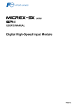
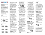
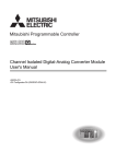
1
series USER’S MANUAL 4CH Resistance Thermometer Element Input Module <Type: NP1AXH4-PT> 6CH High-Accuracy Resistance Thermometer Element Input Module <Type: NP1AXH6G-PT> FEH208c Preface Thank you for purchasing a Fuji Electric Programmable Controller MICREX-SX Series SPH. This user's manual describes the specifications and operating method of the following modules: 4CH Resistance Thermometer Element Input Module (type: NP1AXH4-PT) 6CH High-Accuracy Resistance Thermometer Element Input Module (type: NP1AXH6G-PT) Read this manual carefully to ensure correct operation. When using modules or peripheral devices, be sure to read the corresponding user's manuals listed below: <SX-Programmer Expert (D300win)> Title Manual No. Contents User's Manual Instruction, MICREX-SX series FEH200 Explains the memory, language and system definitions of the MICREX-SX series. User's Manual Hardware, MICREX-SX series SPH FEH201 Explains the system configuration, the specifications and operations of modules in the MICREX-SX series. User's Manual D300win <Reference>, MICREX-SX series FEH257 Explains the methods for installing, the functions and the operations of D300winV3. User's Manual D300win <LD/FBD Editor>, MICREX-SX series FEH257-1 Explains the operations of LD/FBD added to D300winV3. <SX-Programmer Standard (Standard loader)> Title Manual No. Contents User's Manual Instruction, MICREX-SX series FEH588 Explains the memory, language and system definitions of the MICREX-SX series. User's Manual Hardware, MICREX-SX series SPH FEH201 Explains the system configuration, the specifications and operations of modules in the MICREX-SX series. User's Manual SX-Programmer Standard <Reference>, MICREX-SX series FEH590 Explains the functions and the operations of SX-Programmer Standard. * This manual is structured to be applicable to both SX-Programmer Expert (D300win) and SX-Programmer Standard. * In addition to the above manuals, the following Fuji Electric FA Components & Systems Co., Ltd. site offers various manuals and technical documents associated with MICREX-SX. URL http://www.fujielectric.co.jp/fcs/eng/ Notes 1. This manual may not be reproduced in whole or part in any form without prior written approval by the manufacturer. 2. The contents of this manual (including specifications) are subject to change without prior notice. 3. If you find any ambiguous or incorrect descriptions in this manual, please write them down (along with the manual No. shown on the cover) and contact FUJI. Safety Precautions Be sure to read the “Safety Precautions” thoroughly before using the module. Here, the safety precautions items are classified into “Warning” and “Caution”. Warning : Incorrect handling of the device may result in death or serious injury. Caution : Incorrect handling of the device may result in minor injury or physical damage. Even some items indicated by “Caution” may result in a serious accident. Both safety instruction categories provide important information. Be sure to strictly observe these instructions. The items to be cared most are shown below: Warning Never touch any part of charged circuits as terminals and exposed metal portion while the power is turned ON. It may result in an electric shock to the operator. Turn OFF the power before mounting, dismounting, wiring, maintaining or checking, otherwise, electric shock, erratic operation or troubles might occur. Place the emergency stop circuit, interlock circuit or the like for safety outside the PLC. A failure of PLC might break or cause problems to the machine. Do not connect in reverse polarity, charge (except rechargeable ones), disassemble, heat, deform, throw in a fire or short-circuit the batteries, otherwise, they might burst or take fire. If batteries have any deformation, spilled fluids, or other abnormality, do not use them. The use of such batteries might cause explosion or firing. Safety Precautions Caution Do not use one found damaged or deformed when unpacked, otherwise, fire, failure or erratic operation might be caused. Do not shock the product by dropping or tipping it over, otherwise, it might be damaged or troubled. Follow the directions of the operating instructions and manual when mounting the product. If mounting is improper, the product might drop or develop problems or erratic operations. Use the rated voltage and current mentioned in the operating instructions and manual. Use beyond the rated values might cause fire, erratic operation or failure. Operate (keep) in the environment specified in the operating instructions and manual. High temperature, high humidity, condensation, dust, corrosive gases, oil, organic solvents, excessive vibration or shock might cause electric shock, fire, erratic operation or failure. Select a wire size to suit the applied voltage and carrying current. Tighten the wire terminals to the specified torque. Inappropriate wiring or tightening might cause fire, malfunction or failure, or might cause the product to drop from its mounting. Contaminants, wiring chips, iron powder or other foreign matter must not enter the device when installing it, otherwise, fire, accident, erratic operation or failure might occur. Remove the dust-cover seals of modules or units after wiring, otherwise, fire, accident, erratic operation or failure might occur. Connect the ground terminal to the ground, otherwise, electric shock or erratic operation might occur. Periodically make sure the terminal screws and mounting screws are securely tightened. Operation at a loosened status might cause fire or erratic operation. Put the furnished connector covers on unused connectors, otherwise, erratic operation or failure might occur. Put the furnished terminal covers on the terminal blocks, otherwise, electric shock or fire might occur. Sufficiently make sure of safety before program change, forced output, starting, stopping or anything else during a run. Wrong operation might break or cause problems to the machine Engage the loader connector in a correct orientation, otherwise, an erratic operation might occur. Before touching the PLC, discharge any static electricity that may have been collected on your body. To discharge it, touch a grounded metallic object. Static electricity might cause erratic operation or failure. Be sure to install the electrical wiring correctly and securely, observing the directions of the operating instructions and manual. Wrong or loose wiring might cause fire, accident or failure. When disengaging the plug from the outlet, do not pull the cord, otherwise, break of cable might cause fire or failure. Do not attempt to change system configurations (such as installing or removing I/O modules) while the power is ON, otherwise, erratic operation or failure might occur. Do not attempt to repair the module by yourself, but contact your Fuji Electric agent. When replacing the batteries, correctly and securely connect the battery connectors, otherwise, fire, accident or failure might occur. Do not remodel or disassemble the product, otherwise, failure might occur. Follow the regulations of industrial wastes when the device is to be discarded. The modules covered in these operating instructions have not been designed or manufactured for use in equipment or systems which, in the event of failure, can lead to loss of human life. If you intend to use the modules covered in these operating instructions for special applications, such as for nuclear energy control, aerospace, medical or transportation, please consult your Fuji Electric agent. Be sure to provide protective measures when using the module covered in these operating instructions in equipment which, in the event of failure, can lead to loss of human life or other grade results. External power supply (such as 24 V DC power supply) which is connected to DC I/O should be strongly isolated from AC power supply. (Use of EN60950 conforming power supply is recommended.) Otherwise, accident or failure might be caused. Revisions * The manual No. is printed at the bottom right of the cover of this manual. Printed on *Manual No. Revision contents Sep. 2002 FEH208 First edition Aug. 2004 FEH208a The operating method when SX-Programmer Standard is used was added. Jan. 2007 FEH208b The specifications of 6CH High-Accuracy Thermometer Element Input Module were added. Oct. 2007 FEH208c The sampling period of NP1AXH6G-PT was changed. Contents Preface Safety Precautions Revisions Contents Section 1 Overview 1-1 Features .......................................................................................................................................... 1-1 1-2 Program Loader Version Supported ............................................................................................ 1-1 Section 2 Specifications 2-1 General Specifications .................................................................................................................. 2-1 2-2 Performance Specifications .......................................................................................................... 2-2 2-2-1 List of performance specifications ..................................................................................................... 2-2 2-2-2 List of platinum resistance thermometer elements ......................................................................... 2-4 2-3 Functional Specifications ............................................................................................................. 2-11 2-3-1 2-3-2 2-3-3 2-3-4 Functions of NP1AXH4-PT ................................................................................................................ 2-11 Functions of NP1AXH6G-PT ............................................................................................................. 2-11 Control output functions ................................................................................................................... 2-13 Alarm functions ................................................................................................................................. 2-14 2-4 Names and Functions ................................................................................................................... 2-16 2-4-1 Names .............................................................................................................................................. 2-16 2-4-2 Functions ........................................................................................................................................... 2-16 2-5 Dimensions .................................................................................................................................... 2-18 Section 3 System Configuration 3-1 Mounting on Base Board ............................................................................................................... 3-1 3-1-1 Mounting position ............................................................................................................................... 3-1 3-1-2 Number of mountable modules ......................................................................................................... 3-2 Section 4 Software Interface 4-1 Parameter of NP1AXH4-PT ............................................................................................................ 4-1 4-2 Memory Assignments of NP1AXH4-PT .......................................................................................... 4-2 4-3 Programming Procedure of NP1AXH4-PTC ................................................................................. 4-8 4-3-1 Program for reading temperature conversion values ....................................................................... 4-8 4-3-2 Parameter set program ...................................................................................................................... 4-9 4-4 Parameter of NP1AXH6G-PT ........................................................................................................ 4-10 4-5 Memory Assignments of NP1AXH6G-PT ...................................................................................... 4-11 4-5-1 Memory assignments in normal operation ..................................................................................... 4-11 4-5-2 Memory assignments in parameter read/write mode ..................................................................... 4-12 Section 5 Wiring 5-1 NP1AXH4-PT ................................................................................................................................... 5-1 5-1-1 Signal assignments to terminals ...................................................................................................... 5-1 5-1-2 Wiring example ................................................................................................................................... 5-1 5-2 NP1AXH6G-PT ................................................................................................................................. 5-2 5-2-1 Signal assignments to terminals ...................................................................................................... 5-2 5-2-2 Wiring example ................................................................................................................................... 5-2 Appendix 1 Reference Resistance Values of Platinum Resistance............ App.1-1 Appendix 2 Circuit Block Diagram .................................................... App.2-1 Section 1 Overview 4CH Resistance Thermometer Element Input Module (type: NP1AXH4-PT) and 6CH High-Accuracy Thermometer Element Input Module (type: NP1AXH6G-PT) are I/O modules of the MICREX-SX series to convert the temperature values input from Platinum Resistance Thermometer Element (Pt100/JPt100) to INT-type digital data. NP1AXH4-PT and NP1AXH6G-PT will be referred to as “this module” below. 1-1 Features This module allows connecting sensors (platinum resistance thermometer elements) in accordance with both old JIS (JIS C 1604-1981) and new JIS (JIS C 1604-1989). The set values are set once for all channels. Errors (wire breaking or shortcircuit in sensors) can be detected. Celsius or Fahrenheit may be selected. Simple temperature control by ON/OFF operations (2-position operations) is enabled. (for NP1AXH4-PT only) The digital filter set function allows reducing the fluctuation of measured values due to noise. If there is any difference between measured and actual temperature values, it can be reduced to zero by the PV offset function. By setting the unit of temperature conversion value to "%," connection with expansion FB such as PID operation FB can be made easily. Thirteen alarm functions are provided. (for NP1AXH4-PT only) 1-2 Program Loader Version Supported Type Program loader version supported NP1AXH4-PT D300win V2: V2.1.0.0 or later D300win V3: V3.0.0.0 or later Standard loader: V2.0.0.0 or later NP1AXH6G-PT D300win V3: V3.3.6.0 or later Standard loader: V2.3.0.0 or later * The latest version of D300winV3 and Standard loader can be downloaded from Fuji Electric FA Components & Systems Co., Ltd. site. 1-1 Section 2 Specifications 2-1 General Specifications Item Specification Physical Operating ambient environmental temperature conditions Storage (transportation) temperature 0 to + 55 Mechanical service conditions Electrical service conditions -20 to 70 Relative humidity 20 to 95%RH, no condensation Pollution degree 2 (no condensation) Corrosion immunity Free from corrosive gases. Not stained with organic solvents Corrosive gas Free from corrosive gases. Operating altitude 2000 m or less above sea level Transport condition: 70 kPa (equivalent to 3000 m above sea level) or more Vibration Half amplitude: 0.15 mm, Constant acceleration: 19.6 m/s2 2 hours in each of X, Y and Z directions, total 6 hours Shock Peak acceleration: 147 m/s2, 3 cycles in each direction Noise immunity Rise time 1 ns, pulse width 1 μs, 1.5 kV (noise simulator) Electrostatic discharge Contact discharge: 6 kV, Aerial discharge: 8 kV Radioelectromagnetic field 10 V/m (80 MHz to 1,000 MHz) Isolation method NP1AXH4-PT: Between external terminals and internal logic: transformer, photocoupler Between channels: transformer NP1AXH6G-PT: Between external terminals and internal logic: transformer, photocoupler Between channels: transformer Dielectric strength NP1AXH4-PT: 500 V AC, 1 minute (between I/O terminals and frame ground, and between channels) NP1AXH6G-PT: 1000 V AC, 1 minute (between I/O terminals and frame ground, and between channels) Insulation resistance 10 MΩ or more with 500 V DC megger (between I/O terminals and frame gound) Internal current consumption NP1AXH4-PT: 24 V DC, 150 mA or less (supplied from power supply module) NP1AXH6G-PT: 24 V DC, 150 mA or less (supplied from power supply module) Installation conditions Structure Panel-mounted type, IP30 Cooling method Air cooling Mass NP1AXH4-PT: approx. 240g NP1AXH6G-PT: approx. 300g Outside dimensions W35*H105*D111 mm (with projection 21 mm) 2-1 Section 2 Specifications 2-2 Performance Specifications 2-2-1 List of performance specifications (1) NP1AXH4-PT Item Specification Number of input channels 4 Available resistance thermometer elements See "2-2-2(1) List of platinum resistance thermometer elements supported by NP1AXH4-PT." Use the selection switch on the module rear panel to set the element. (Note1) Accuracy (for full scale) 0.3%, 1 digit (ambient temperature 18 to 28 ) (Note 2) 0.7%, 1 digit (ambient temperature 0 to 55 ) Maximum noise deviation (for full scale) 0.7% (when shielded twisted pair cable is used.) (Note 3) Allowable input wire resistance (per wire) 100Ω or less Sampling period 500 ms or less/4 channels Input filter time Hardware (time constant): 50 ms or less Digital filter time: 1 to 100 s (Default value is 1s, setting enabled in increment of 1s.) Wire connections External wire connections Detachable screw terminal block (M3) 20 poles Applicable wire size AWG#22-18 Treatment of terminals unused Shortcircuit (For details, see "5-1-2 Wiring example.") Cable used Shielded twisted pair cable Alarm functions 13 alarm types (For details, see "2-3-4 Alarm functions.") Number of occupied slots 1 Number of occupied input/output words 8 input words and 8 output words Note 1: The element is set at once for all channels. It cannot be set for individual channels. Note 2: In the range of 0.0 to 100.0 , or -20.0 to 80.0 , the accuracy for full scale is as follows: 0.4%, 1 digit (ambient temperature 18 to 28 ) 0.8%, 1 digit (ambient temperature 0 to 55 ) Note 3: In the range of 0.0 to 100.0 , or -20.0 to 80.0 , the maximum noise deviation for full scale is 0.8%. [Reference] If there is a discrepancy between the temperature data measured with this module and actual temperature (the indication of a recorder or a high-accuracy thermometer measured under the same conditions as this module), correct the discrepancy using the “PV Offset Function.” 2-2 Section 2 Specifications 2-2 Performance Specifications (2) NP1AXH6G-PT Item Specification Number of input channels 6 Available resistance thermometer elements See "2-2-2(2) List of platinum resistance thermometer elements supported by NP1AXH6G-PT." Use the selection switch on the module rear panel to set the element. (Note 1) Reference accuracy 0.05% or 0.07 , whichever is greater (ambient temperature 18 to 28 Temperature coefficient 0.007%/ Maximum noise deviation (for full scale) 0.2% (when shielded twisted cable is used) ) Allowable input wire resistance (per wire) 20Ω or less Sampling period Version earlier than V2131: 80ms or less/6 channels Version V2131 or later: 45ms or less/6 channels Input filter time Hardware (time constant): 30 ms or less Digital filter time: 1 to 100 s, moving average 4/8/16/32 times (Default value is moving average 32 times, setting enabled in increment of 1s.) Wire connections External wire connections Detachable screw terminal block (M3) 20 poles Applicable wire size AWG#22-18 Treatment of terminals unused Shortcircuit (For details, see "5-2-2 Wiring example.") Cable used Shielded twisted pair cable Number of occupied slots 1 Number of occupied input/output words 8 input words and 4 output words Note 1: The element is set at once for all channels. It cannot be set for individual channels. [Reference] If there is a discrepancy between the temperature data measured with this module and actual temperature (the indication of a recorder or a high-accuracy thermometer measured under the same conditions as this module), correct the discrepancy using the “PV Offset Function.” 2-3 Section 2 Specifications 2-2 Performance Specifications 2-2-2 List of platinum resistance thermometer elements (1) List of platinum resistance thermometer elements supported by NP1AXH4-PT Resistance thermometer element type PT JPT Celsius ( Set No. ) Fahrenheit ( Temperature Data resolution measurement range Set No. ) Temperature Data resolution measurement range 00 0 to 200 24 32 to 392 01 -20 to 80 25 -4 to 176 02 0 to 100 26 32 to 212 03 0 to 400 27 32 to 752 1 04 -200 to 200 28 -328 to 392 05 -200 to 600 29 -328 to 1112 06 0.0 to 200.0 30 32.0 to 392.0 07 -20.0 to 80.0 31 -4.0 to 176.0 08 0.0 to 100.0 32 32.0 to 212.0 09 0.0 to 400.0 33 32.0 to 752.0 10 -200.0 to 200.0 34 -328.0 to 392.0 11 -200.0 to 600.0 35 -328.0 to 1112.0 12 0 to 200 36 32 to 392 13 -20 to 80 37 -4 to 176 14 0 to 100 38 32 to 212 15 0 to 400 39 32 to 752 16 -200 to 200 40 -328 to 392 17 -200 to 500 41 -328 to 932 18 0.0 to 200.0 42 32.0 to 392.0 19 -20.0 to 80.0 43 -4.0 to 176.0 20 0.0 to 100.0 44 32.0 to 212.0 21 0.0 to 400.0 45 32.0 to 752.0 22 -200.0 to 200.0 46 -328.0 to 392.0 23 -200.0 to 500.0 47 -328.0 to 932.0 0.1 1 0.1 * If a number not listed above is set, a SW (switch) error occurs. * For NP1AXH4-PT, 5% of the span is over range and under range. 2-4 1 0.1 1 0.1 Section 2 Specifications 2-2 Performance Specifications (2) List of platinum resistance thermometer elements supported by NP1AXH6G-PT Resistance thermometer element type PT JPT Celsius ( Set No. ) Fahrenheit ( Temperature Data resolution measurement range Set No. ) Temperature Data resolution measurement range 00 0 to 200 31 32 to 392 01 -20 to 80 32 -4 to 176 02 0 to 100 33 32 to 212 03 0 to 400 34 32 to 752 04 -200 to 200 35 -328 to 392 05 -200 to 600 - - 06 -200 to 850 36 -328 to 1562 07 0.0 to 200.0 37 32.0 to 392.0 08 -20.0 to 80.0 38 -4.0 to 176.0 09 0.0 to 100.0 10 0.0 to 400.0 11 1 39 32.0 to 212.0 40 32.0 to 752.0 -200.0 to 200.0 - - 12 -200.0 to 600.0 41 -328.0 to 1112.0 13 -200.0 to 850.0 42 -328.0 to 1562.0 14 -20.00 to 80.00 35 -4.00 to 176.00 15 0 to 200 44 32 to 392 16 -20 to 80 45 -4 to 176 17 0 to 100 46 32 to 212 18 0 to 400 - - 19 -200 to 200 47 -328 to 392 20 -200 to 500 48 -328 to 932 21 0.0 to 200.0 49 32.0 to 392.0 22 -20.0 to 80.0 50 -4.0 to 176.0 23 0.0 to 100.0 51 32.0 to 212.0 24 0.0 to 400.0 52 32.0 to 752.0 25 -200.0 to 200.0 53 -328.0 to 392.0 26 -200.0 to 500.0 54 -328.0 to 932.0 0.1 0.01 1 0.1 1 0.1 0.01 1 0.1 * If a number not listed above is set, it is assumed to be “00” and operation is started. In addition, do not use “99” because it is a reserved number. 2-5 Section 2 Specifications 2-2 Performance Specifications (3) Characteristic curve for NP1AXH6G-PT * Numbers in parentheses are set Nos. 1) 0 to 200 C (PT: 00), (JPT: 15) 2) -20 to 80 C (PT: 01), (JPT: 16) Conversion value (INT type) Conversion value (INT type) 90 80 220 200 Practical temperature input range -20 Practical temperature input range -30 -20 Temperature ( ) 0 0 200 220 -20 80 90 Temperature ( ) -20 -30 3) 0 to 100 C (PT: 03), (JPT: 17) 4) 0 to 400 C (PT: 04), (JPT: 18) Conversion value (INT type) Conversion value (INT type) 110 100 440 400 Practical temperature input range Practical temperature input range -10 -40 Temperature ( ) 0 -10 100 110 5) -200 to 200 C (PT: 03), (JPT: 19) Temperature ( ) 0 -40 400 440 Conversion value (INT type) 220 200 -210 -200 Temperature ( ) 0 200 220 Practical temperature input range -200 -210 2-6 Section 2 Specifications 2-2 Performance Specifications * Numbers in parentheses are set Nos. 6) -200 to 600 C (PT: 05) Conversion value (INT type) 640 600 Practical temperature input range -210 -200 0 Temperature ( ) 600 640 -200 -210 7) -200 to 850 C (PT: 06) Conversion value (INT type) 860 850 Practical temperature input range -210 -200 Temperature ( ) 0 850 860 -200 -210 8) -200 to 500 C (JPT: 20) Conversion value (INT type) 510 500 Practical temperature input range -204 -200 0 500 510 -200 -204 2-7 Temperature ( ) Section 2 Specifications 2-2 Performance Specifications * Numbers in parentheses are set Nos. 9) 0.0 to 200.0 C (PT: 07), (JPT: 21) 10) -20.0 to 80.0 C (PT: 08), (JPT: 22) Conversion value (INT type) Conversion value (INT type) 2200 2000 900 800 Practical temperature input range Practical temperature input range -30.0 -20.0 -20.0 0 200.0 -200 220.0 Temperature ( ) 0 80.0 90.0 Temperature ( ) -200 -300 11) 0.0 to 100.0 C (PT: 09), (JPT: 23) 12) 0.0 to 400.0 C (PT: 10), (JPT: 24) Conversion value (INT type) Conversion value (INT type) 1100 1000 4400 4000 Practical temperature input range Practical temperature input range -10.0 -40.0 Temperature ( ) 0 100.0 110.0 -100 13) 0.0 to 100.0 C (PT: 11), (JPT: 25) Temperature ( ) 0 400.0 440.0 -400 Conversion value (INT type) 2200 2000 Practical temperature input range -210.0 -200.0 0 200.0 220.0 -2000 -2100 2-8 Temperature ( ) Section 2 Specifications 2-2 Performance Specifications * Numbers in parentheses are set Nos. 14) -200.0 to 600.0 C (PT: 12) Conversion value (INT type) 6400 6000 Practical temperature input range -210.0 -200.0 0 600.0 640.0 Temperature ( ) -2000 -2100 15) -200.0 to 850.0 C (PT: 13) Conversion value (INT type) 8600 8500 Practical temperature input range -210.0 -200.0 0 850.0 860.0 Temperature ( ) -2000 -2100 16) -200.0 to 500.0 C (PT: 20) Conversion value (INT type) 5100 5000 Practical temperature input range -204.0 -200.0 0 500.0 510.0 -2000 -2040 2-9 Temperature ( ) Section 2 Specifications 2-2 Performance Specifications * Numbers in parentheses are set Nos. 17) -20.00 to 80.00 C (PT: 14) Conversion value (INT type) 9000 8000 Practical temperature input range -30.00 -20.00 0 -2000 -3000 80.00 Temperature ( ) 90.00 2-10 Section 2 Specifications 2-3 Functional Specifications 2-3-1 Functions of NP1AXH4-PT Item Description Control output functions See "2-3-3 Control output functions." Digital filter function Soft-filter provided for reducing the fluctuation of measured values due to disturbance. The filter value can be set for each channel. Wire breaking/shortcircuit detection function Detects wire breaking or shortcircuit of sensors. The detection flag is assigned to "error status" of the module for each channel. PV offset function Allows compensating the difference between the measured and actual temperature values. Conversion value % output function Allows easy connection to PID operation FB, etc. (making unnecessary the use of the industrial value conversion program). Temperature input enable/disable function By disabling channels unused, output of the wire-break and shortcircuit alarms for these channels can be inhibited. Alarm functions Available for delaying alarms at system startup, etc. For details, see "2-3-4 Alarm functions." Up/down scale set function Allows the fail-safe function to prevent abnormal heating or cooling when temperature measurement errors have occurred. * For the setting method, see “Section 4 Software Interface.” 2-3-2 Functions of NP1AXH6G-PT (1) List of functions Item Description Digital filter function Soft-filter provided for reducing the fluctuation of measured values due to disturbance. The digital filter value can be set for each channel. Wire breaking/shortcircuit detection function Detects wire breaking or shortcircuit of sensors. When detected, the over (or under) range value of a conversion value is shown in temperature conversion value/status for each channel. Set the over range and under range with the "up/down scale set function." "Up scale" is selected by default; the over range value is shown. * For the over range/under range value of the resistance thermometer element used, see "2-3-2(2) List of over range/under range." PV offset function Allows compensating the difference between the measured and actual temperature values. Conversion value % output function Outputs conversion values in percent (%). Allows easy connection to PID operation FB, etc. (making unnecessary the use of the industrial value conversion program). Temperature input enable/disable function By disabling channels unused, detection of wire breaking and shortcircuit of these channels can be inhibited. Up/down scale set function Allows the fail-safe function to prevent abnormal heating or cooling when temperature measurement errors have occurred. * For the setting method, see “Section 4 Software Interface.” 2-11 Section 2 Specifications 2-3 Functional Specifications (2) List of over range/under range Celsius ( ) Resistance Temperature thermometer element Set No. measurement range PT JPT Under range value Over range value 00 0 to 200 -20 220 01 -20 to 80 -30 90 02 0 to 100 -10 110 03 0 to 400 -40 440 04 -200 to 200 -210 220 05 -200 to 600 -210 640 06 -200 to 850 -210 860 07 0.0 to 200.0 -200 2200 08 -20.0 to 80.0 -300 900 09 0.0 to 100.0 -100 1100 10 0.0 to 400.0 -400 4400 11 -200.0 to 200.0 -2100 2200 12 -200.0 to 600.0 -2100 6400 13 -200.0 to 850.0 -2100 8600 14 -20.00 to 80.00 -3000 9000 15 0 to 200 -20 220 16 -20 to 80 -30 90 17 0 to 100 -10 110 18 0 to 400 -40 440 19 -200 to 200 -210 220 20 -200 to 500 -204 510 21 0.0 to 200.0 -200 2200 22 -20.0 to 80.0 -300 900 23 0.0 to 100.0 -100 1100 24 0.0 to 400.0 -400 4400 25 -200.0 to 200.0 -2100 2200 26 -200.0 to 500.0 -2040 5100 2-12 Section 2 Specifications 2-3 Functional Specifications 2-3-3 Control output functions (for NP1AXH4-PT only) This module has an internal control output flag for 2-position (ON/OFF) operation. By outputting the control output flag through the digital output module, simple temperature control using ON/OFF control is enabled. The parameter values necessary for control output operation are “SV value (set value),” “control output operation” and “ON/OFF dead zone.” The “control output RUN/STOP” command (bits 0 to 3 at offset address +8) is used to enable or disable the control output operation. Dead zones (available set range: 0.5% to 20.0%) Control output ON/OFF operation Example: When dead zone is 10 5 5 ON OFF SV * About forward/backward operation Backward operation Dead zone Temperature Forward operation The control output flag (bits 0 to 3 at offset address +0) goes OFF when the measured temperature value is greater than the SV value (set value). This is used for temperature control by heating and set by default. The control output flag (bits 0 to 3 at offset address +0) goes ON when the measured temperature value is greater than the SV value (set value). This is used for temperature control by cooling. Measured temperature value SV value Dead zone Time ON Forward operation Backward operation OFF 2-13 Section 2 Specifications 2-3 Functional Specifications 2-3-4 Alarm functions (for NP1AXH4-PT only) Alarm code 0 Meaning Diagram PV Upper limit absolute value ALM1 1 Lower limit absolute value 2 Lower limit absolute value with lower limit holding PV ALM1 ALM1 3 PV Upper limit deviation SV 4 Lower limit deviation 5 Lower limit deviation with lower limit holding 6 Upper/lower limit absolute value 7 Upper/lower limit absolute value with lower limit holding 8 Upper/lower limit deviation 9 Upper/lower limit deviation with lower limit holding 10 ALM1 PV SV PV ALM2 ALM1 ALM2 ALM1 PV SV Upper limit + upper-upper limit absolute value PV ALM1 ALM2 11 Lower limit + lower-lower limit absolute value PV ALM2 ALM1 ALM2 12 Upper limit + upper-upper limit deviation PV ALM1 SV ALM2 13 Lower limit + lower-lower limit deviation PV ALM1 SV 2-14 Section 2 Specifications 2-3 Functional Specifications <About alarms with holding> An alarm with holding does not allow the alarm flag to go ON immediately when the measured value enters an alarm range; it allows an alarm to occur when the measured value once goes out of and then re-enters the alarm range. Upper limit deviation ALM1 SV ALM2 Lower limit deviation ALM1 Upper/lower limit deviation alarm ALM2 ALM1 Upper/lower limit deviation alarm with holding ALM2 No alarms occur here. Measurement start <Alarm dead band> An alarm dead band is provided such that alarm won’t be so sensitively signaled even when temperature input value fluctuates in the vicinity of ALM setting value. The dead band is 1% the range span (the full scale of temperature input). When upper limit 1% the range span Dead band ON OFF ALM set value When lower limit 1% the range span Dead band ON OFF ALM set value 2-15 Section 2 Specifications 2-4 Names and Functions 2-4-1 Names 1) Status indication LED 4) Version seal 3) Resistance thermometer element type selection switch 2) Detachable terminal block Nameplate Front view Rear view 2-4-2 Functions 1) Status indication LEDs Indicate the status of this module. Symbol Color Description ONL Green Remains ON while the local module is normally operating and blinking while the SX bus is connected. ERR Red Remains ON when the local module is abnormal. <Example of status indication> Status ONL ERR In initialization Blinking OFF In normal operation ON OFF Stopped due to fatal fault OFF ON In operation with nonfatal fault ON ON 2) Detachable terminal block This is a detachable terminal block with 20 M3 terminals. For terminal layout, see “Section 5 Wiring.” For connections, be sure to use solderless terminals and securely tighten them. (The tightening torque is 0.5 to 0.7 N m.) 2-16 Section 2 Specifications 2-4 Names and Functions 3) Resistance thermometer element type selection switch Sets the resistance thermometer element type at once for all channels. The same No. as the “Set No.” of the resistance thermometer element to be used must be set. For set numbers, see “2-2-2 List of resistance thermometer elements.” These switches are factory-configured as follows: NP1AXH4-PT “07” (Pt -20.0 to 80.0 ) NP1AXH6G-PT “08” (Pt -20.0 to 80.0 ) Note: Different resistance thermometer elements cannot be connected to individual channels. 4) Version seal Indicates the hardware and firmware versions of this module. 20 30 Hardware version Firmware version 2-17 Section 2 Specifications 2-5 Dimensions Unit: mm 111 90 105 35 2-18 Section 3 System Configuration 3-1 Mounting on Base Board 3-1-1 Mounting position This module is connected to the MICREX-SX Series SPH SX bus or I/O master module link (remote I/O). The allowable slots on the base board are shown below. <8/11/13-slot base board> Any slots except those for the power module (two leftmost slots on the base board) are available. Available slots <3/6-slot base board> Available slots Note: This module can also be mounted on the base board of substations such as T-link, OPCN-1, or DeviceNet. Available slots <Restrictions for adjacent modules> When modules for controlling AC signals are installed on one or both sides of NP1AXH4-PT, set the digital filter value (parameter) for this module to “5s” or more. NP1AXH4-PT I/O I/O I/O I/O CPU I/O modules for controlling AC signals such as AC input and RY output modules 3-1 Section 3 System Configuration 3-1 Mounting on Base Board 3-1-2 Number of mountable modules The SX bus allows to connect a maximum of 238 modules and the maximum configuration may have a maximum of 254 modules including those on the I/O master link. Note that the number of modules that can be connected is limited by the I/O (I/Q) area capacity (512 words) occupied by NP1AXH4-PT or NP1AXH6G-PT. NP1AXH4-PT occupies 16 words (8 input and 8 output words). Therefore, the maximum number of NP1AXH4-PT that can be connected to the SX bus in one configuration is: 512 words/16 words = 32 (modules) Also, NP1AXH6G-PT occupies 12 words (8 input and 4 output words). Therefore, the maximum number of NP1AXH6G-PT that can be connected to the SX bus in one configuration is: 512 words/12 words >= 42 (modules) 3-2 Section 4 Software Interface 4-1 Parameter of NP1AXH4-PT Parameter name Set range (unit) Initial value Update timing PV offset value -10.0% to 10.0% (0.1%) (Note 1) 0% Digital filter value 1 to 100 s (1 s) (Notes 1 and 2) 1s Control output operation set ON: Forward operation OFF: Backward operation OFF: Backward operation When writing parameters from application (note 4) Conversion value unit set ON: % OFF: Industrial value OFF: Industrial value Up/down scale processing ON: Down scale processing OFF: Up scale processing OFF: Up scale processing Alarm ON delay time 0 to 100s (1 s) (Note 1) 0s Alarm type 0 to 13 (Note 1) 0: Upper limit absolute value SV value (temperature set value) Industrial value of 0 to 100% of full scale (Note 3) Industrial value of 50% of full scale ALM1 set value Industrial value of 80% of full scale ALM2 set value Industrial value of 20% of full scale ON/OFF dead zone Industrial value of 0.5 to 20.0% of full scale Industrial value of 0.5% of full scale Note 1: Two set items should be set in one word-type word. An example is given below. Set both the word-type channel 2 and 1 PV offset values. (MSB) 15 (LSB) 0 +10 Channel 2 PV offset value Channel 1 PV offset value +11 Channel 4 PV offset value Channel 3 PV offset value <Set example> When setting -10.0% for channel 1 and 5.0% for channel 2, set “9C32h” in the area at offset address +10, because -10.0% -100 9C (h) and 5.0% 50 32 (h). Note 2: When a value less than 1s or more than 100s is set, it is actually set to 1s or 100s, respectively. Note 3: For example, for Pt 0-200 of resistance thermometer element type No. 00, the set range is 0 to 200 with increments of 1 . Note 4: For parameter writing from an application, the data is written in EEPROM in this module. Create the application so that the count of writing to EEPROM does not exceed 100,000, which is the guaranteed count. 4-1 Section 4 Software Interface 4-2 Memory Assignments of NP1AXH4-PT NP1AXH4-PT occupies 16 words in the I/O area (8 input and 8 output words). Offset address (MSB) 15 (LSB) 0 +0 Information status, control output +1 ALM1/2 output, alarm enabled/disabled status +2 Error status +3 Selection command status NP1AXH4-PT CPU module +4 +5 +6 Temperature conversion value/ parameter area +7 +8 Set command +9 Selection command +10 +11 CPU module NP1AXH4-PT +12 Parameter value set area +13 +14 +15 4-2 Section 4 Software Interface 4-2 Memory Assignments of NP1AXH4-PT (1) Information status, control output (offset address +0) 15(F) 8 7 0 CH4 CH3 CH2 CH1 +0 Unused CH4 CH3 CH2 CH1 Unused Temperature input enabled/disabled status ON: Enabled OFF: Disabled Control output ON: Control output ON OFF: Control output OFF BUSY ON: In processing OFF: Processing completed (access enabled) Mode display ON: Parameter set/read mode OFF: Temperature conversion value read mode For details of the parameter, see “4-2 Parameter of NP1AXH4-PT.” (2) ALM1/2, alarm enabled/disabled status (offset address +1) 15(F) 8 7 0 CH4 CH3 CH2 CH1 CH4 CH3 CH2 CH1 CH4 CH3 CH2 CH1 +1 Unused Alarm enabled/ disabled status ON: Enabled OFF: Disabled ALM2 alarm output ON: ALM2 alarm detected ALM1 alarm output ON: ALM1 alarm detected (3) Error status (offset address +2) 15(F) +2 8 7 0 CH4 CH3 CH2 CH1 CH4 CH3 CH2 CH1 CH4 CH3 CH2 CH1 Shortcircuit alarm *2 ON: Shortcircuit detected OFF: Normal Wire-break alarm Temperature *1 ON: Wire breaking measurement error detected ON: Error detected OFF: Normal Goes ON when wire breaking or shortcircuit is detected. OFF: Normal ON: EEPROM calibration value error (fatal fault) ON: EEPROM user set value error ON: Setting error in type selection switch Goes ON when the set value is outside the allowable range (00 to 47). *1 Goes ON when signal line A, B, or b is broken or when the resistance of resistance thermometer element is 350Ω or more. *2 Goes ON when the resistance of the resistance thermometer element is 15Ω or less. Changes in temperature conversion value for errors 1) When this module detects a temperature measurement error (wire breaking or shortcircuit), it stores the upper limit +5% (up scale) or lower limit -5% (down scale) of the resistance thermometer element used to the register as the temperature conversion value depending on the settings in operational parameter “up/down scale processing.” 2) When an EEPROM calibration value error is detected, the temperature conversion value goes to “0.” 3) Even when an EEPROM user set value error is detected, the temperature conversion value changes in the range for the resistance thermometer element type specified. If this error occurs, set the parameter again. 4) When a type set switch setting error occurs, the resistance thermometer element type is set to “00” (Pt0 to 200 ). 4-3 Section 4 Software Interface 4-2 Memory Assignments of NP1AXH4-PT (4) Selection command status (offset address +3) Indicates the parameter currently being written or read by this module. 15(F) +3 0 8 0 0 0 Unused CH4 CH3 CH2 CH1 Channel No. 7 0 0 0 Unused Operational parameter 1 write mode (at once for all channels) Operational parameter 2 write mode (for individual channels) Operational parameter 1 read mode (at once for all channels) Operational parameter 2 read mode (at once for all channels) Operational parameter 3 read mode (at once for all channels) Operational parameter 4 read mode (for individual channels) (5) Temperature conversion value/status (offset addresses +4 to +7) This register stores the temperature conversion values and set parameters for each channel. The kind of information stored is shown in the “mode display” bit (bit 15) of the information status (offset address +0) and the bit information of the selection command status (offset address +3). Mode display Busy flag flag Selection command status Display mode (information stored in registers +4 to +7) OFF OFF OFF Temperature conversion value read mode ON OFF Bit 2 is ON. Operational parameter 1 read mode ON OFF Bit 3 is ON. Operational parameter 2 read mode ON OFF Bit 4 is ON. Operational parameter 3 read mode ON OFF Bit 5 and the bit corresponding to the channel No. are ON. Operational parameter 4 read mode 4-4 Section 4 Software Interface 4-2 Memory Assignments of NP1AXH4-PT 1) Temperature conversion value read mode Allows storing the temperature conversion value (INT-type) for each channel. 15(F) 0 +4 Channel 1 Temperature conversion value +5 Channel 2 Temperature conversion value +6 Channel 3 Temperature conversion value +7 Channel 4 Temperature conversion value Note: When the temperature conversion display is set to “% value,” the range is 0.00 to 105.00% of the temperature range for the selected resistance thermometer element. When the temperature conversion display is set to “industrial value,” the temperature range for the selected resistance thermometer element has an under range of -5% and an over range of +5%. 2) Operational parameter 1 read mode Allows storing the word-type PV offset and digital filter values for each channel. 15(F) 0 +4 Channel 2 PV offset value Channel 1 PV offset value +5 Channel 4 PV offset value Channel 3 PV offset value +6 Channel 2 Digital filter value Channel 1 Digital filter value +7 Channel 4 Digital filter value Channel 3 Digital filter value 3) Operational parameter 2 read mode Allows storing the word-type alarm ON delay time and alarm type for each channel. 15(F) 0 +4 Channel 1 Alarm ON delay time Channel 1 Alarm type +5 Channel 2 Alarm ON delay time Channel 2 Alarm type +6 Channel 3 Alarm ON delay time Channel 3 Alarm type +7 Channel 4 Alarm ON delay time Channel 4 Alarm type 4) Operational parameter 3 read mode Allows storing the parameter values (word-type) shown below. 15(F) 0 Platinum resistance thermometer element type No. +4 +5 Unused Control output operation Conversion value unit +6 Unused +7 Unused 15(F) 8 7 Up/down scale 0 CH4 CH3 CH2 CH1 CH4 CH3 CH2 CH1 CH4 CH3 CH2 CH1 +5 Unused Conversion value unit set ON: % value OFF: Industrial value Up/down scale processing ON: Down scale processing OFF: Up scale processing Control output operation ON: Forward operation OFF: Backward operation 4-5 Section 4 Software Interface 4-2 Memory Assignments of NP1AXH4-PT 5) Operational parameter 4 read mode Allows storing the parameter values (INT-type) shown below for each channel. 15(F) 0 +4 SV value (set value) +5 ALM1 set value +6 ALM2 set value +7 ON/OFF dead zone Because operational parameter 4 is stored for each channel, the channel related to the stored information should be determined by checking which one of bits 8-11 at offset address +3 is ON. (6) Set command (offset address +8) 15 14 13 12 11 10 9 8 7 6 5 4 3 2 1 0 CH4 CH3 CH2 CH1 CH4 CH3 CH2 CH1 CH4 CH3 CH2 CH1 +8 Unused Enable temperature input ON: Enable OFF: Disable Enable alarm ON: Enable OFF: Disable Enable control output ON: Enable control output OFF: Disable control output ON: Parameter set request Note: If the control output is ON when it is disabled, the control output flag goes OFF. (7) Selection command (offset address +9) 15(F) +9 0 8 0 0 Unused 0 CH4 CH3 CH2 CH1 Channel No. 7 0 0 0 Unused Operational parameter 1 write mode (at once for all channels) Operational parameter 2 write mode (for individual channels) Operational parameter 1 read mode (at once for all channels) Operational parameter 2 read mode (at once for all channels) Operational parameter 3 read mode (at once for all channels) Operational parameter 4 read mode (for individual channels) Note 1: Set ON only one of bits 0 to 5. If two or more bits are ON, the specified mode is not validated and the previous mode remains unchanged. Note 2: Set ON only one of bits 8 to 11 when “operational parameter 2 write mode” or “operational parameter 4 read mode” is specified. If two or more bits are ON (channel numbers duplicated), the specified mode is not validated and the previous mode remains unchanged. 4-6 Section 4 Software Interface 4-2 Memory Assignments of NP1AXH4-PT (8) Parameter set (offset addresses +10 to +15) When bit 15 of the set command (offset address +8) is set ON, bit 15 of the information status (offset address +0) goes ON and “parameter set/read mode” is set. Next, input the set data to this register to set ON the corresponding bit of the selection command. 1) Operational parameter 1 write mode Set data in the positions shown below to set ON “operational parameter 1 write mode flag” (bit 0 of the selection command). 15(F) 0 +10 Channel 2 PV offset value Channel 1 PV offset value +11 Channel 4 PV offset value Channel 3 PV offset value +12 Channel 2 digital filter value Channel 1 digital filter value +13 Channel 4 digital filter value Channel 3 digital filter value +14 Unused Control output operation Conversion value unit set +15 Up/down scale Unused 15(F) 8 7 0 CH4 CH3 CH2 CH1 CH4 CH3 CH2 CH1 CH4 CH3 CH2 CH1 +14 Unused Conversion value unit set ON: % value OFF: Industrial value Up/down scale processing ON: Down scale processing OFF: Up scale processing Control output operation ON: Forward operation OFF: Backward operation 2) Operational parameter 2 write mode Allows setting data in the positions shown below and setting ON “operational parameter 2 write mode flag” (bit 1 of the selection command). Set operational parameter 2 for each channel. * When D300win is used, assign WORD type variables to “Alarm ON delay time” and “Alarm type”, and assign INT type variables to other parameters. 15(F) +10 0 Alarm ON delay time Alarm type +11 SV value (temperature set value) +12 ALM1 set value +13 ALM2 set value +14 ON/OFF dead zone +15 Unused WORD type INT type 4-7 Section 4 Software Interface 4-3 Programming Procedure of NP1AXH4-PT 4-3-1 Program for reading temperature conversion values Except when setting or reading parameters, the temperature conversion read mode remains allowing to store the temperature conversion value of each channel in the input/output area (offset addresses +4 to +7) where NP1AXH4-PT is allocated. (1) Temperature conversion value read procedure When mode selection is not specified from the application, “temperature conversion value read mode” is usually set by default. Therefore, the application program can read the temperature conversion values only by checking that temperature conversion value read mode is active (bit 15 of offset address +0 is set OFF) and that no error has occurred on the module (bit 14 of offset address +0 is set OFF). (2) Sample program NP1AXH4-PT SX bus station No. 2 To platinum resistance thermometer element 1) Sample program when D300winV2 is used A sample program to check mode and error occurrence, using a selector instruction, and then to acquire temperature data is shown below. In this example, temperature data “ch1_temp_data” becomes zero if an error has occurred or if temperature conversion value read mode is not active. <Code worksheet example> <Variable worksheet example> Note: In case of temperature measurement error, a value of measuring range 5% is stored in the temperature conversion value register (“ch1_input” in this example), depending on the setting of up scale/down scale. For example, when up scale is specified and measuring range is 0 to 400 , “420” is stored. The interlock when an abnormal value is stored in the temperature conversion value register should be set by application program as needed. When normal When temperature measurement error occurs 4-8 Section 4 Software Interface 4-3 Programming Procedure of NP1AXH4-PT 2) Sample program when standard loader is used A sample program to check mode and error occurrence, using a selector instruction, and then to acquire temperature data is shown below. In this example, temperature data becomes zero if an error has occurred or if temperature conversion value read mode is not active. Note: In case of temperature measurement error, a value of measuring range 5% is stored in the temperature conversion value register (“ch1_input” in this example), depending on the setting of up scale/down scale. For example, when up scale is specified and measuring range is 0 to 400 , “420” is stored. The interlock when an abnormal value is stored in the temperature conversion value register should be set by application program as needed. 4-3-2 Parameter set program This module has 11 related parameters. To set all items, “operational parameter 1” and “operational parameter 2” should be set. <Parameter set program creation procedure> Create the application program in the procedure given below. 1) Check that the mode display flag (bit 15) and busy flag (bit 14) of the information status (offset address +0) are OFF and set data in the parameter set area (offset addresses +10 to +15). 2) Set write mode and set channel (for operational parameter 2 write mode) in the selection command (offset address +9). 3) Set ON the parameter set request flag (bit 15) of the set command (offset address +8). 4) The mode display of the information status goes ON (parameter set/read mode) and the parameters are written in the module EEPROM. Using the selection command, check that the set parameter values have been correctly written. 5) After checking that the parameters have been correctly written, set OFF the parameter set request flag of the set command. 4-9 Section 4 Software Interface 4-4 Parameter of NP1AXH6G-PT Parameter name Set range (unit) Initial value Update timing PV offset value -10.0% to 10.0% (0.1%) 0% Digital filter value 1 to 100 s (1 s) or Moving average: 4/8/16/32 times Moving average 32 times When writing parameters from application (Note) Conversion value unit set ON: % OFF: Industrial value OFF: Industrial value Up/down scale processing ON: Down scale processing OFF: Up scale processing OFF: Up scale processing Note: For parameter writing from an application, the data is written in EEPROM in this module. Create the application so that the count of writing to EEPROM does not exceed 100,000, which is the guaranteed count. 4-10 Section 4 Software Interface 4-5 Memory Assignments of NP1AXH6G-PT NP1AXH6G-PT occupies 12 words in the I/O area (8 input and 4 output words). 4-5-1 Memory assignments in normal operation The resistance thermometer element type to be used is set for all channels at once with the resistance thermometer element type selection switch on the module rear panel. Offset address (MSB) 15 (LSB) 0 +0 Channel 1 Temperature conversion value / status +1 Channel 2 Temperature conversion value / status +2 Channel 3 Temperature conversion value / status +3 Channel 4 Temperature conversion value / status +4 Channel 5 Temperature conversion value / status +5 Channel 6 Temperature conversion value / status +6 NP1AXH6G-PT CPU module Unused +7 +8 Set command +9 Selection command CPU module NP1AXH6G-PT +10 Unused +11 Temperature conversion values are output to offset addresses +0 to +5. However, when greater than 32700 (INT type), statuses are indicated. <Status list> Status code Condition of modul Description 32701 (7FBDh) Parameter read/write mode Parameter read/write mode is activated when bit 15(F) of the set command (offset address +8) is set ON. This status is notified to channel 1 (offset address +0) only. 32702 (7FBEh) EEPROM calibration data error (Fatal fault) If the calibration data of EEPROM is destroyed or if EEPROM cannot be written or read, this error is notified. Module internal EEPROM is abnormal. If this error occurred, it is necessary to replace the module. 32703 (7FBFh) If the user setting data of EEPROM is destroyed, this error is notified. EEPROM user setting data error If this error occurred, all parameters need to be reset. If this error recurs even after parameters are reset, it is necessary to replace the module. 32704 (7FC0h) Power supply error If the internal power supply of this module becomes down, this error is notified. If this error recurs even after the system power is reset, it is necessary to replace the module. 4-11 Section 4 Software Interface 4-5 Memory Assignments of NP1AXH6G-PT 4-5-2 Memory assignments in parameter read/write mode Parameter read/write mode is activated when bit 15(F) of the set command (offset address +8) is set ON. In parameter read/ write mode, the following parameters can be read and set. <Reading parameters> Offset address (MSB) 15 (LSB) 0 +0 Status +1 Selection status +2 Channel status +3 Read parameter 1 +4 Read parameter 2 +5 Read parameter 3 +6 NP1AXH6G-PT CPU module Unused +7 +8 Set command +9 Set channel +10 Parameter set data 1 +11 Parameter set data 2 CPU module NP1AXH6G-PT 4-12 Section 4 Software Interface 4-5 Memory Assignments of NP1AXH6G-PT (1) Status (offset address +0) (Read only) Indicates “32701 (7FBDh)” when this module is in parameter read/write mode. 15(F) 0 +0 Status indication 32701(7FBDh): Parameter read/write mode (2) Selection command status (offset address +1) (Read only) Indicates which parameter mode is currently activated. One of the bits goes ON. 15(F) +1 0 8 0 0 0 7 0 Unused 0 0 0 0 0 Operational parameter (read) (at once for all channels) Unused Digital filter (read) (for individual channels) PV offset (read) (for individual channels) Write parameter reset (at once for all channels) Operational parameter (write) (at once for all channels) Digital filter (write) (for individual channels) PV off set (write) (for individual channels) (3) Channel status (offset address +2) (Read only) Indicates which channel of parameter is currently being written or read. When one of the following bits of “set command register” is set ON, the bit corresponding to the target channel No. is set ON. Bit 1 : Digital filter (read) Bit 2 : PV offset (read) Bit 10 : Digital filter (write) Bit 11 : PV offset (write) 15(F) 8 7 0 CH6 CH5 CH4 CH3 CH2 CH1 +2 Unused Unused 4-13 Section 4 Software Interface 4-5 Memory Assignments of NP1AXH6G-PT (4) Read parameter (offset addresses +3 to +5) (Read only) Reads parameters set in this module. What is to be read depends on which bit of the selection command status is set ON. 1) When operational parameter (read) (bit 0 of the selection command status is set ON) 8 15(F) 7 0 +3 Temperature input enable/disable setting status Up/down scale setting status +4 Unused Conversion value indication setting status Platinum resistance thermometer element type No. (INT type) setting status +5 15(F) 8 7 0 CH6 CH5 CH4 CH3 CH2 CH1 CH6 CH5 CH4 CH3 CH2 CH1 +3 Unused Unused Temperature input enable/disable setting status ON: Disabled, OFF: Enabled 15(F) 8 Up/down scale processing status ON: Down scale, OFF: Up scale 7 0 CH6 CH5 CH4 CH3 CH2 CH1 +4 Unused Conversion value indication setting status ON: %, OFF: Industrial value 2) When digital filter (read) (bit 1 of the selection command status is set ON) Indicates the setting status of the digital filter. As shown in the figure below, the register is shared between channels 1 and 2, channels 3 and 4, and channels 5 and 6. 15(F) 8 0 7 +3 Digital filter setting status Channel 1/2 +4 Digital filter setting status Channel 3/4 +5 Digital filter setting status Channel 5/6 3) When PV offset (read) (bit 2 of the selection command status is set ON) Indicates the status of the PV offset. As shown in the figure below, the register is shared between channels 1 and 2, channels 3 and 4, and channels 5 and 6. 15(F) 8 0 7 +3 PV offset value setting status Channel 1/2 +4 PV offset value setting status Channel 3/4 +5 PV offset value setting status Channel 5/6 * Bits 8 to 11 of the selection command status indicates that parameter write mode is currently active. When these bits are set ON, the contents of the read parameter are not updated, or reset to 0. 4-14 Section 4 Software Interface 4-5 Memory Assignments of NP1AXH6G-PT (5) Set command (offset address +8) (Write register) Switches from normal operation to parameter read/write mode or sets the parameter type. 15(F) 8 0 +8 0 0 7 0 0 0 0 Unused 0 0 0 Operational parameter (read) (at once for all channels) Unused Digital filter (read) (for individual channels) PV offset (read) (for individual channels) Write parameter reset (at once for all channels) Operational parameter (write) (at once for all channels) Digital filter (write) (for individual channels) Parameter read/write mode PV off set (write) (for individual channels) (6) Set channel (offset address +9) Specifies which channel of parameter is to be written or read. When one of the following bits of “set command register” is set ON, this register is enabled. Bit 1 : Digital filter (read) Bit 2 : PV offset (read) Bit 10 : Digital filter (write) Bit 11 : PV offset (write) 15(F) 8 7 0 CH6 CH5 CH4 CH3 CH2 CH1 +9 Unused Unused Note: Set ON only one of bits 8 to 11. If two or more bits are ON (channel numbers duplicated), the specified mode is not validated and the previous mode remains unchanged. (7) Parameter set data 1 and 2 (offset addresses +10 and +11) Input parameters to be set in the this module. What is to be set depends on which bit of the set command is set ON. 1) When operational parameter (write) (bit 9 of the set command is set ON) 8 15(F) 7 0 +10 Temperature input enable/disable setting status Up/down scale setting status +11 Unused Conversion value indication setting status 15(F) 8 7 CH6 CH5 CH4 CH3 CH2 CH1 CH6 CH5 CH4 CH3 CH2 CH1 +10 Unused Temperature input enable/disable setting status ON: Disabled, OFF: Enabled 15(F) 8 0 Unused Up/down scale processing status ON: Down scale, OFF: Up scale 7 0 CH6 CH5 CH4 CH3 CH2 CH1 +11 Unused Conversion value indication setting status ON: %, OFF: Industrial value 4-15 Section 4 Software Interface 4-5 Memory Assignments of NP1AXH6G-PT 2) When filter (write) (bit 10 of the set command is set ON) Sets the soft filter (0 to 100s) and number of moving average times. Offset address +10 is shared between channels 1, 2, 3 and 4, and offset address +11 between channels 5 and 6. 8 15(F) 7 0 +10 Filter setting status Channel 1/2/3/4 +11 Filter setting status Channel 5/6 When the set value is between 0 and 100: Digital filter setting (1 to 100s) When the set value is between 101 and 104: Moving average setting 101: Moving average 4 times 102: Moving average 8 times 103: Moving average 16 times 104: Moving average 32 times 3) When PV offset (write) (bit 11 of the set command is set ON) Offset address +10 is shared between channels 1, 2, 3 and 4, and offset address +11 between channels 5 and 6. 8 15(F) 7 +10 PV offset Channel 1/2/3/4 +11 PV offset Channel 5/6 0 Set a value within plus or minus 10% of the temperature conversion value range. When a value exceeding the range is set, it is assumed to be a value within plus or minus 10%. 4-16 Section 5 Wiring 5-1 NP1AXH4-PT 5-1-1 Signal assignments to terminals Channel 1 Channel 2 Channel 3 Channel 4 b1 2 SLD 4 b2 6 SLD 8 NC 10 NC 12 b3 14 SLD 16 b4 18 SLD 20 1 A1 3 B1 5 A2 7 B2 9 NC 11 NC 13 A3 15 B3 17 A4 19 B4 5-1-2 Wiring example Numbers in parentheses are terminal Nos. Channel 1 A1 b1 pt B1 SLD (1) (2) (3) (4) Channel 2 A2 b2 pt (Note 3) When channel 3 is not used, short-circuit between teminals A3 and b3. (5) B2 SLD (6) (7) (8) NC (9) NC NC NC (10) (11) (12) A3 b3 B3 SLD (13) (14) (15) (16) A4 b4 (17) (18) (19) (20) (Note 2) Channel 4 pt B4 SLD (Note 1) Class-D grounding Note Note Note Note Note 1: 2: 3: 4: 5: Use class-D grounding for specially high noise. The SLD terminal is internally connected. Do not use the NC terminal as a relay terminal to other signals or control power. When connecting this module, use a shielded compensating lead wire with a very low resistance that can be ignored. For wiring of A, b, and B, use the same length of wires so that the impedance becomes equal. In particular, do not short-circuit between terminals B and b. 5-1 Section 5 Wiring 5-2 NP1AXH6G-PT 5-2-1 Signal assignments to terminals Channe 2 Channe 4 b1 2 A2 4 B2 6 b3 8 A4 10 B4 12 b5 Channe 6 14 A6 16 B6 18 SLD 20 1 A1 3 B1 5 b2 7 A3 9 B3 11 b4 13 A5 15 B5 17 b6 19 SLD Channe 1 Channe 3 Channe 5 5-2-2 Wiring example Numbers in parentheses are terminal Nos. Channel 1 pt A1 b1 B1 (1) (2) (3) A2 b2 B2 (4) (5) (6) A3 b3 B3 (7) (8) (9) A4 b4 B4 (10) A5 b5 B5 (13) (14) A6 b6 (16) (17) B6 (18) SLD SLD (19) (20) Channel 2 pt Channel 3 pt Channel 4 pt Channel 5 pt When channel 6 is not used, short-circuit between teminals A6 and b6. (11) (12) (Note 2) (15) (Note 1) Class-D grounding Note Note Note Note Note 1: 2: 3: 4: 5: Use class-D grounding for specially high noise. The SLD terminal is internally connected. Do not use the NC terminal as a relay terminal to other signals or control power. When connecting this module, use a shielded compensating lead wire with a very low resistance that can be ignored. For wiring of A, b, and B, use the same length of wires so that the impedance becomes equal. In particular, do not short-circuit between terminals B and b. 5-2 Appendix 1 Reference Resistance Values of Platinum Resistance Ω, R100/R0 = 1.3851) 1. Pt100 reference resistance values (R0 = 100Ω JIS C 1604-1997 (Unit: Ω) Temperature ( ) -100 -0 Temperature ( ) 0 100 200 300 400 500 600 -0 60.26 100.00 0 100.00 138.51 175.86 212.05 247.09 280.98 313.71 -10 56.19 96.09 10 103.90 142.29 179.53 215.61 250.53 284.30 316.92 -20 52.11 92.16 20 107.79 146.07 183.19 219.15 253.96 287.62 320.12 -30 48.00 88.22 30 111.67 149.83 186.84 222.68 257.38 290.92 323.30 -40 43.88 84.27 40 115.54 153.58 190.47 226.21 260.78 294.21 326.48 -50 39.72 80.31 50 119.40 157.33 194.10 229.72 264.18 297.49 329.64 -60 35.54 76.33 60 123.24 161.05 197.71 233.21 267.56 300.75 -70 31.34 72.33 70 127.08 164.77 201.31 236.70 270.93 304.01 -80 27.10 68.33 80 130.90 168.48 204.90 240.18 274.29 307.25 -90 22.83 64.30 90 134.71 172.17 208.48 243.64 277.64 310.49 2. JPt100 reference resistance values (R0 = 100Ω Ω, R100/R0 = 1.3916) JIS C 1604-1997 (Unit: Ω) Temperature ( ) -100 -0 Temperature ( ) 0 100 200 300 400 500 -0 59.57 100.00 0 100.00 139.16 177.13 213.93 249.56 284.02 -10 55.44 96.02 10 103.97 143.01 180.86 217.54 253.06 287.40 -20 51.29 92.02 20 107.93 146.85 184.58 221.15 256.55 -30 47.11 88.01 30 111.88 150.67 188.29 224.74 260.02 -40 42.91 83.99 40 115.81 154.49 191.99 228.32 263.49 -50 38.68 79.96 50 119.73 158.29 195.67 231.89 266.94 -60 34.42 75.91 60 123.64 162.08 199.35 235.45 270.38 -70 30.12 71.85 70 127.54 165.86 203.01 238.99 273.80 -80 25.80 67.77 80 131.42 169.63 206.66 242.53 277.22 63.68 90 135.30 173.38 210.30 246.05 280.63 -90 App.1-1 Appendix 2 Circuit Block Diagram The circuit block diagram of NP1AXH4-PT and NP1AXH6G-PT is shown below. NP1AXH6G-PT/NP1AXH4-PT Platinum resistance thermometer element Photocoupler isolation A/D conversion circuit Internal logic circuit Transformer isolation Platinum resistance thermometer element SX bus interface Photocoupler isolation A/D conversion circuit Transformer isolation Transformer isolation Platinum resistance thermometer element A/D conversion circuit Photocoupler isolation SLD SLD Vref Constant current circuit A MPX b B AG App.2-1 SX bus Gate City Ohsaki, East Tower, 11-2, Osaki 1-chome, Shinagawa-ku, Tokyo 141-0032, Japan E-mail: [email protected] URL: http://www.fujielectric.com/ Materials covered in this document are subject to revision due to the modification of the product. Issued as FE consolidated edition, June 2011