1
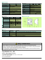
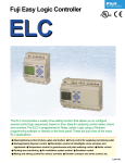
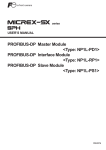
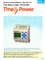
MICRO PROGRAMMABLE CONTROLLER
Fuji Easy Logic Controller
The TimeRy Power is provided with a weekly time-setting feature and the ability to
configure various control logic with software. This timer relay can be widely used as a
replacement for relays in such applications as listed below.
● Opening/closing control of doors, gates and shutters ● Pump control for supplying and draining water
● Garbage disposer control ● Illumination control of streetlights, show windows and signboards
● Temperature control in greenhouses and plant watering control ● Boiler control
● Parking area monitoring ● Air ventilation system control ● Escalator control
● Mixing and stirring control for various solvents ● Transfer conveyor and sorter control, etc.
LEH110
4 power relays, 15 timers, 8 counters and 8 program timers are packed into a single TimeRy Power.
SPACE SAVING, COST SAVING, WIRE SAVING, ENERGY SAVING, TIME SAVINGÉ
The TimeRy Power is helpful to increase all types of SAVINGS!
Drastically minaturized control panels!
TimeRy Power has an extremely compact size of 72 x 90 x 55 mm. This
compact size contributes to the drastic reduction of control panel dimensions.
SPACE SAVING
For example, if a control circuit
including 3 timers and 4 power
relays is replaced with TimeRy
Power, the mounting space may
be reduced by about 50%! (As
compared with our existing
models.)
About 50%
Reduced hardware cost!
TimeRy Power is priced to sell at a user-oriented lower
price.
This will greatly lighten the burden of hardware costs.
For example,
if a control circuit including 3 timers and 4 power relays
is replaced with TimeRy Power, the cost will be reduced
by about 20%! (As compared with our existing models.)
COST SAVING
Less wiring manpower!
WIRE SAVING
ENERGY SAVING
In the conventional method, the troublesome wiring of timers
and counters and connection of discrete components is
inevitable. TimeRy Power allows a wired logic function to be
achieved with programmed software through operation of
operation switches. Thus the more complicated the logic
becomes, the more the wiring manpower will be reduced! In
addition, minor modifications can be quickly implemented with
the operation switches on the spot, and thus TimeRy Power
will powerfully help the user promote standardized hardware
specifications!
Energy-saving operation
with consideration to the
environment!
Promotion of
highly efficient
production!
TimeRy Power allows the user
to promote environmentally
friendly measures through plant
operation with reduced
consumption of electricity and
fuel! This energy-saving
operation is realised by such
functions as automatic schedule
management with daily and
weekly timers, and temperature
control with analog inputs.
TimeRy Power comes
standard with logic schemes
for control applications of
routine plants and systems.
TimeRy Power can easily
copy logic schemes by use
of the optional memory pack.
The control logic connections
take considerably less time
to implement than traditional
hard-wiring.
TIME SAVING
4 power relays, 15 timers, 8 counters and 8 program timers are packed into a single TimeRy Power.
SPACE SAVING, COST SAVING, WIRE SAVING, ENERGY SAVING, TIME SAVINGÉ
The TimeRy Power is helpful to increase all types of SAVINGS!
Digital input terminals
Power supply terminals
Analog input terminals
Power supply terminals for 100 to
200 AC and 24V DC are provided.
Model with 24V DC RTC comes
standard with analog inputs.
Monitoring screen
Screen displays logic diagram and
monitoring operating conditions.
Operation switches
Operation switches are used for
wiring logic and setting timers and
counters.
Interface port
Digital output terminals
Power relays with large capacity
of 10A are provided onboard
An interface port is provided for
connection to a loader or to attach
a memory pack.
Monitoring screen displays all operating conditions
Special mounting hardware is not required
The monitoring screen on the front of TimeRy Power
indicates to the user the total status of TimeRy Power at a
glance. This screen displays the status of l/Os, internal
relays, timers, counters, the analog current values and the
clock time, as well as a monitoring screen of the control
logic operation.
TimeRy Power can be mounted with screws on sliding
type fixing holes as well as DIN rails without using any
special mounting clamps.
Control logic is easily configured in ladder diagram format with software
Control logic wiring in TimeRy Power is implemented with
software in a ladder diagram format that is developed
from a traditional relay schematic diagram. The user has
only to wire the TimeRy Power with software as is shown
in an existing schematic diagram.
Large power output relays with switching capacity of lOA are provided
TimeRy Power includes large power output relays with a
per point switching capacity of 10A at 250V AC, or 8A at
30V DC. These output relays can be directly connected to
illumination lamps, valves and small motors for control.
Schedule management is achieved by using clock function
A model with a clock function is provided so that the user
may simply and economically realize daily or weekly
schedule management using just a single TimeRy Power
without any expensive time switch required In addition,
overseas use such as in Europe is also ensured since the
clock function is equipped with a summer-time selection
function.
2 channel analog inputs are standard (DC 24 V, with RTC)
TimeRy Power comes equipped with 2 channel analog
inputs as a standard. Simple control of analog quantities,
such as temperature, speed, and voltage can be achieved
without any optional analog device.
Password feature is provided for security
TimeRy Power contains a password feature for preventing
unexpected modification of software with switch operation.
Maintenance-free EEPROM is used
Since software information is stored into an EEPROM that
does not require battery backup, TimeRy Power can be
handled without any consideration for the maintenance
that would be necessary in the case of hardware logic.
Complies with CE marking and UL/cUL standards
The TimeRy Power is widely applicable throughout the
world, and the standard model complies with various
global standards such as CE marking and UL.
Software data saving with loader and simulation via
personal computer are available
Software data can be saved by using an optional loader
program. The data will help the user to standardize wiring
diagrams. Wiring of loader software is implemented in a
similar manner as for
TimeRy Power.
Moreover' the
configured logic can
be simulated in a
personal computer,
and therefore
performance of the
logic scheme in
TimeRy Power can
be verified prior to
installation.
■ Specifications
● General specifications
Power supply voltage
Power consumption
Output current
Electrostatic discharge
● Specifications
NQ2P10R-14 [1
20.4 to 28.8V DC
0.3W
Max.10A
IEC801-2 Severity3
NO2P10R-52
85 to 264V AC
0.8W
Contact discharge ±4kV, aerial discharge ±8kV
Radioelectromagnetic field
Operating ambient
temperature
Relative humidity
Vibration
Shock
Construction
Dimensions
IEC801 -3 10V/m
IEC801-4 Severity3 2kV
0 to 55¡C
20 to 90%RH no condensation
IEC68-2-6 9.8m/s2
IEC68-2-27 147m/s2
IP20
72 x 90 x 52mm (DIN rail)
Input
Operating voltage
Delay time
Analog voltage*
Output
No. of output points
Load current
NQ2P10RQ2P10R- C
Ladder, function brock
240steps (4elements x 60lines)
Built-in EEPROM, memory pack option
12points (11 to C)
8points (Q1 to Q8)
15points (M1 to MF)
8points (C1 to C8)
15points (T1 to TF)
4points (P1 to P4)
4points (G1 to G4)
X
2channel (A1 to A2) only for DC
X
O
■ Dimensions (mm)
● I/O specifications
No. of input points
Rated voltage
Rated current
Programming language
Program memory capacity
Backup
Input relay
Output relay
Auxiliary relay
RTC relay
Counter
Timer
Analog comparison
Analog input
RTC
NQ2P10R-14
6points
0 to 28.8V DC
3mA
NQ2P10R-52
0 to 265V AC
0.5mA/110V
1mA/220V
ON:79 to 265V
OFF:0 to 40V
OFF
ON:50ms
ON
OFF:50ms
Ð
ON:15 to 28.8V
OFF:0 to 5V
OFF
ON:3ms
ON
OFF:5ms
0 to 10V DC
Resolution:8bits
4points
10A/250V AC or 8A/30V DC
*Analog input:only for NQ2P1 OR-14C
■ Products
Item
TimeRy Power
Loader software
Memory pack
Ordering code
(Product code)
NQ2P1 OR-14
NQ2P1 OR-14C
NQ2P1 OR-52
NQ2P1 OR-52C
NQ4H-SE
NQ8P-MP
Specification
24V DC power supply, input 6points, output 4points Ry10A, no clock function
24V DC power supply, input 6points, output 4points Ry10A, clock function, analog 2channel
100 to 200V AC power supply, input 6points, output 4points Ry10A, no clock function
100 to 200V AC power supply, input 6points, output 4points Ry10A, clock function
Personal computer loader software (with connection cable)
For program saving and transferring
Safety Considerations
● For safe operation, before using the product read the instruction manual or user manual that comes with the
product carefully or consult the Fuji sales representative from which you purchased the product.
● Some of the products listed in this catalog may have limits on their use or location or may require periodic
inspections. Call Fuji's sales representative for further information.
● For safe operation, wiring should be conducted only by qualified engineers who have sufficient technical
knowledge about electrical work or wiring.
¥Appearance and specifications are subject to change without prior notice for the purpose of product improvement.
Fuji Electric Co., Ltd.
ED & C ¥ Drive Systems Company
Gate City Ohsaki, East Tower
11-2, Osaki 1-chome, Shinagawa-ku, Tokyo, 141-0032, Japan
Phone: +81-3-5435-7135~8
Fax: +81-3-5435-7456~9
Materials covered in this document are subject to revision due to the modification of the product.
Printed in Japan 2000-3 (COO/COO) M50 FIS