1
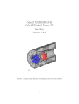
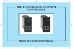
Fuji Easy Logic Controller
R
ELC
The ELC incorporates a weekly time-setting function that allows you to configure
several control logic sequences based on time. Ideal for replacing control relays, timers
and counters. The ELC is programmed in Relay Ladder Logic using a Windows
programming software or directly on the front panel. These are just a few of the many
ELC applications:
○ ○ ○ ○ ○ ○ ○ ○ ○ ○ ○ ○ ○ ○ ○ ○ ○ ○ ○ ○ ○ ○ ○ ○ ○ ○ ○ ○ ○ ○ ○ ○ ○ ○ ○ ○ ○ ○ ○ ○ ○ ○ ○ ○ ○ ○ ○ ○ ○ ○ ○ ○ ○ ○ ○ ○ ○ ○ ○ ○ ○ ○ ○ ○ ○
● Opening/closing control of doors, gates and shutters ● Pump control for supplying and draining water
● Garbage/waste disposer control ● Illumination control of streetlights, show windows and
signboards ● Temperature control in greenhouses and plant watering control ● Boiler control
● Parking area monitoring ● Air ventilation system control ● Escalator control
● Mixing and stirring control for various solvents ● Transfer conveyor and sorter control, etc.
LAH110a
4/8 power relays, 15 timers, 8 counters and 8 program timers are packed into a single ELC.
SAVE SPACE, REDUCE COST, REDUCE WIRING, LOWER ENERGY CONSUMPTION,
SAVE TIME ••••• •The ELC will help improve productivity.
Digital input terminals
Drastically reduce the size of your control panel!
COMPACT
The ELC has an extremely compact size. The 10-point type is only 72 × 90 × 57mm and
the 20-point type is only 126 × 90 × 57mm in size. This compact size contributes to the
drastic reduction of control panel dimensions
* For example, if a control circuit
including 3 timers and 4 power
relays are replaced with the ELC
(10 points type), the mounting space
may be reduced by about 50%!
Power supply terminals
Analog input terminals
Power supply terminals for 100 to
200V AC and 24V DC.
Model with 24V DC RTC comes
standard with analog inputs.
* About 50%
Monitoring screen
SAVE SPACE
* (Compared to Relays, Timers, Counters combined)
Screen displays logic diagram and
monitoring operating conditions.
Reduce hardware cost!
COST
DOWN
Digital output terminals
Power relays with large capacity of
10A are provided onboard.
* For example,
if a control circuit including 3 timers and 4 power relays
are replaced with the ELC (10 points type), the cost will
be reduced by about 20%!
Reduce wiring time
When individual Relays, Timers and Counter are used the
wiring of each component becomes tedious. The ELC can
drastically reduce the wiring the because only 1 component is
involved. Further more, if changes to the logic need to be
made these can be done in software or via the front panel.
Special mounting hardware is not required
The monitoring screen on the front of the ELC indicates to the
user the total status of the ELC at a glance.
This screen displays the status of I/Os, internal relays, timers,
counters, the analog current values and the clock time, as well
as a monitoring screen of the control logic operation.
The ELC can be mounted with screws on sliding type
mounting holes as well as DIN rails without using any
special mounting clamps.
Control logic is easily configured in ladder diagram format with software
Since software information is stored into an EEPROM that
does not require battery backup, the ELC is maintenance
free.
Large power output relays with switching capacity of 10A are provided
The ELC includes large power output relays with a per
point switching capacity of 10A at 250V AC, or 8A at 30V
DC. These output relays can be directly connected to
illumination lamps and valves for control.
Schedule management is achieved by using clock function
Improve
Productivity
Energy-saving operation.
LOWER ENERGY
CONSUMPTION
The ELC can be programmed
to save electricity. A time
management function can be
programmed to shutdown
Fans, Lights, etc. to save
energy.
TIME
SAVE TIME
The ELC comes standard with
Relay Ladder logic schemes
for control applications.
The ELC can easily copy
logic schemes by using the
optional memory pack.
The control logic connections
take considerably less time to
implement than traditional
hard-wiring.
An interface port is provided for
connection to a loader or to attach
a memory pack.
Monitoring screen displays all operating conditions
Control logic wiring in the ELC is implemented with
software in a ladder diagram format that is developed from
a traditional relay schematic diagram. The user only needs
to program the ELC in Relay Ladder Logic.
REDUCE WIRING
SAVE
ENERGY
Operation switches are used for
writing logic and setting timers and
counters.
Interface port
The ELC has an attractive price to help your bottom line.
Please contact Fuji Electric for more detail.
REDUCE COST
WIRING
Operation switches
The ELC’s equipped with RTC allow the user to program a
daily or weekly control schedule without expensive time
management system. Also, the ELC incorporates day light
savings time.
2 channel analog inputs are standard (DC 24 V, with RTC)
The ELC comes equipped with 2 channel analog inputs
standard. Simple control of analog applications, such as
temperature, speed, and voltage can be achieved without
any optional analog device.
Password feature is provided for security
The ELC contains a password feature for preventing
unexpected modification of software with switch operation.
Maintenance-free EEPROM is used
Complies with CE marking and UL/cUL standards
The ELC is widely applicable throughout the world, with
various global standards such as CE marking and UL.
Software data saving with loader and simulation via personal
computer can be done
Software data can be saved by using the loader software
program. The data will help the user to standardize wiring
diagrams. Also, the configured logic can be simulated in a
personal computer,
and therefore
performance of the
logic scheme in the
ELC can be verified
prior to installation.
■ Specifications
●General specifications
NQ2P10R-14 NQ2P20R-14
NQ2P10R-52 NQ2P20R-52
20.4 to 28.8V DC
85 to 264V AC
2W
3W
3VA
7VA
Max. 10A
IEC801-2 Severity3
Contact discharge ±4kV, aerial discharge ±8kV
Radioelectromagnetic field IEC801-3 10V/m
IEC801-4 Severity3 2kV
Operating ambient
0 to 55˚C
temperature
20 to 90%RH no condensation
Relative humidity
IEC68-2-6
9.8m/s2
Vibration
IEC68-2-27
147m/s2
Shock
IP20
Construction
Programming language
Program memory capacity
Backup
Input relay
Output relay
Auxiliary relay
RTC relay
Counter
Timer
Analog comparison
Analog input
RTC
●I/O specifications
■ Dimensions (mm)
No. of input points
Rated voltage
Rated current
NQ2P10R-14 NQ2P20R-14
6points
12points(10points**)
0 to 28.8V DC
3mA/24V
Input
NQ2P10R-52 NQ2P20R-52
6points
12points
0 to 265V AC
0.5mA/110V 1mA/110V
1mA/230V
2mA/230V
ON:79 to 265V
OFF:0 to 40V
OFF➝ON:50ms
ON➝OFF:50ms
ON:15 to 28.8V
OFF:0 to 5V
OFF➝ON:3ms
Delay time
ON➝OFF:5ms
0 to 10V DC
Analog voltage*
Resolution:8bits
8points
4points
No. of output points 4points
10A/250V AC or 8A/30V DC
Load current
*Analog input: only for NQ2P10R-14C, NQ2P20R-14C
**NQ2P20R-14C
Operating voltage
NQ2P RNQ2P R- C
Ladder, function brock
240steps (4elements x 60lines )
Built-in EEPROM, memory pack option
12points (I1 to C)
8points (Q1 to Q8)
15points (M1 to MF)
8points (R1 to R8)
15points (C1 to C8)
4points (T1 to TF)
4points (G1 to G4)
✕
2channel (A1 to A2) only for DC
✕
2-φ4.5
2-M4x12
L
N
I1
I2
I3
I4
AC 100∼240V
I5
I6
Input 6xAC
TimeRy Power
DEL
SEL
ESC
OK
100
90
Power supply voltage
Power consumption
Output current
Electrostatic discharge
10R-52C
Output 4×Relay/10A
Q1
Q2
Q3
Q4
60
72
52
5
2-φ4.5
2-M4x12
L
N
I1
AC 100∼240V
Output
8points
I2
I3
I4
I5
I6
I7
I8
I9
IA
IB
IC
Input 12xAC
DEL
SEL
ESC
OK
100
90
TimeRy Power
20R-52C
Output 8×Relay/10A
Q1
Q2
Q3
Q4
Q5
110
126
Q6
Q7
Q8
8
52
5
■ Products
Item
TimeRy Power
Loader software
Memory pack
Ordering code
(Product code)
NQ2P10R-14
NQ2P10R-14C
NQ2P10R-52
NQ2P10R-52C
NQ2P20R-14
NQ2P20R-14C
NQ2P20R-52
NQ2P20R-52C
NQ4H-SE
NQ8P-MP
Specifiction
24V DC power supply, input 6points, output 4points Ry10A, no clock function
24V DC power supply, input 6points, output 4points Ry10A, clock function, analog 2channel
100 to 240V AC power supply, input 6points, output 4points Ry10A, no clock function
100 to 240V AC power supply, input 6points, output 4points Ry10A, clock function
24V DC power supply, input 12points, output 8points Ry10A, no clock function
24V DC power supply, input 10points, output 8points Ry10A, clock function, analog 2channel
100 to 240V AC power supply, input 12points, output 8points Ry10A, no clock function
100 to 240V AC power supply, input 12points, output 8points Ry10A, clock function
Personal computer loader software (with connection cable)
For program saving and transferring
Safety Considerations
●For safe operation, before using the product read the instruction manual or user manual that comes withthe
product carefully or consult the Fuji sales representative from which you purchased the product.
●Some of the products listed in this catalog may have limits on their use or location or may require periodic
inspections. Call Fuji's sales representative for further information.
●For safe operation, wiring should be conducted only by qualified engineers who have sufficient technical
knowledge about electrical work or wiring.
●Appearance and specifications are subject to change without prior notice for the purpose of product improvement.
Fuji Electric Corp. of America
Fuji Electric Co., Ltd.
Park 80 West Plaza II
Saddle Brook, NJ 07663, U.S.A.
Phone:
(201) 712-0555
Fax:
(201) 368-8258
URL:
http://www.fujielectric.com
ED & C・Drive Systems Company
Materials covered in this document are subject to revision due to the modification of the product.
Gate City Ohsaki, East Tower
11-2, Osaki 1-chome, Shinagawa-ku, Tokyo, 141-0032, Japan
Phone:
+81-3-5435-7135~8
Fax:
+81-3-5435-7456~9
URL:
http://www.fujielectric.co.jp/edc/
Printed in Japan 2000-12 (L00a/H00) M50 FIS