1
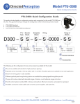
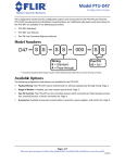
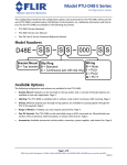
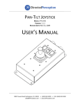
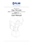
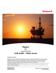
Model PTU-D300-RF
Advanced and Innovative products for the control and positioning of sensors and precision instruments
Quick Configuration Guide
PTU-D300-RF: Quick Configuration Guide
This guide includes details on configuration options and accessories for the model PTU-D300-RF
pan-tilt units. This guide will walk you through the configuration. Other relevant documents include:
•
•
•
PTU-D300-RF Datasheet
PTU-D300 User Manual
Pan-Tilt Unit Command Reference Manual
The following are the configuration choices and accessories available for this model:
1
1.
The pan-tilt is offered in standard, high-speed pan, and D300-EX gearing options.
2
2.
Payloads can be mounted on the top and/or side. A number of bracket options are available to suit each application.
3
3.
The pan-tilt can be ordered with standard ranges of motion or with alternate ranges of motion.
4
4.
Pan-tilt control options include ASCII or binary command set, Ethernet connection, and joystick or gamepad.
5
5.
Available accessories include cables and converters, power supplies, and starter kits.
NOTE: Some configurations of the PTU-D300-RF are available with Inertial Stabilization Module (ISM) option. For further
details see PTU-D300-ISM Configuration Guide.
Page 1
890C Cowan Road Burlingame, California 94010 | Office 650-692-3900 | Fax 650-692-3930 | [email protected] | www.DPerception.com
4/2009
Model PTU-D300-RF
Quick Configuration Guide
1
PTU Type
The PTU-D300-RF is offered standard, with high-speed pan, and as the PTU-D300-EX configuration. See also PTU-D300-EX Configuration
Guide.
High Speed Pan
The High-Speed Pan option provides pan velocities to 100°/second. Output torque
in the pan-axis with the high-speed option is somewhat reduced in relation to the
standard PTU-D300 configuration. This may result in lower payload capacities for
applications requiring high acceleration and/or mounting in other than normal
vertical position.
Ordering:
D300-F__-F-R-0000-__-__
D300-S__-F-R-0000-__-__
High-speed Pan option
Standard-speed Pan option
PTU-D300-EX Gearing Option
The PTU-D300-RF is available with the PTU-D300-EX extreme duty gearing option.
This provides higher payload capacity, along with the other PTU-D300-RF features.
See the PTU-D300-EX datasheet and Configuration Guide for further details on the
PTU-D300-EX features.
Ordering:
D300-U__-F-R-0000-__-__
D300-S__-F-R-0000-__-__
PTU-D300-EX Gearing Option
Standard PTU-D300 Gearing Option
Wiring Pass-Through
The PTU-D300-RF inludes a single DC-18GHz RF channel as well as 8 additional channels for passing video, power, serial, etc.
PTU-D300-RF Payload
Wiring Options
RF (PL03)
# of conductors
(Payload)
Passed Through
SMA (RF)
Power
2
Video
4
General
2
RF (DC-18GHz)
1
Total
8
Signals at Payload
Connector 1 (RF)
SMA (RF)
TTL Outputs
3
PTU Host Control
0
CHA/CHB Serial
6
Base Connector
RS-232 Host Control
YES
RS-485 Host Control
YES
Page 2
890C Cowan Road Burlingame, California 94010 | Office 650-692-3900 | Fax 650-692-3930 | [email protected] | www.DPerception.com
Model PTU-D300-RF
Quick Configuration Guide
2
Bracket Mount
Payloads can be mounted on the top or the side. Side mounting has a higher payload rating than top mount as it reduces the amount of
torque on the tilt axis. The PTU-D300-RF itself can be mounted in any orientation. When mounting in non-vertical orientation, consideration
should be given to gravity effects, depending on payload mounting orientation and balance.
Select among the following options for payload mounting bracket configurations.
Single Side Hub
The PTU-D300-RF comes standard with a single payload mounting hub.
This hub can accept “L” brackets that allow payloads to be mounted on the
side, the top, or the top plus one side. There are two types of “L” brackets,
standard (D300AC-BKT-Lstd) and “heavy duty” (D300AC-BKT-HDS and
D300AC-BKT-HDT). Heavy duty brackets are recommended for payloads
above 20 lbs. The standard bracket can be used either on the side or top.
The heavy duty brackets are available for over the top, or for side use, but
they are not interchangeable (see photos).
Single Side Hub
with D300AC-BKTLstd (side mounted)
Ordering:
D300-__S-F-R-0000-__-__
D300AC-Bkt-Lstd
D300AC-Bkt-HDS
D300AC-Bkt-HDT
single payload mounting hub
Standard “L” bracket
Heavy duty side “L” bracket
Heavy duty top “L” bracket
Single Side Hub
with D300AC-BKTLstd (top mounted)
Dual Side Hubs:
The PTU-D300-RF is available with dual mounting hubs. This configuration
includes a permanently affixed top bracket, and hubs on both sides. Standard “L” brackets (D300AC-BKT-Lstd) and heavy duty “L” brackets (D300ACBKT-HDS) can be used on either or both sides. Payloads can be mounted on
the top plate and/or on attached side “L” brackets. Heavy duty brackets are
recommended for payloads above 20 lbs.
Dual-Side Hubs no “L” brackets
Ordering:
D300-__D-F-R-0000-__-__
D300AC-Bkt-Lstd
D300AC-Bkt-HDS
dual payload mounting hubs
Standard “L” bracket
Heavy duty side “L” bracket
Dual-Side Hubs
- with (2) D300ACBKT-HDS
D300AC-Bkt-Lstd
D300AC-Bkt-HDS
Page 3
890C Cowan Road Burlingame, California 94010 | Office 650-692-3900 | Fax 650-692-3930 | [email protected] | www.DPerception.com
Model PTU-D300-RF
Quick Configuration Guide
3
Ranges of Motion
The PTU-D300-RF calibrates automatically on power-up using an internal precision limit detection system. In order for the unit to calibrate
successfully, it must explore the full range of motion in both axes. If this calibration sequence may potentially interfere with surrounding equipment, modified pan and tilt ranges can be specified at time of order. The calibration sequence can be software controlled, and
supressed at power up. However the sequence must be executed before absolute position commands will be accepted. Range of motion
limits must be set at the factory and cannot be changed by the user.
All PTU-D300-RF configurations include a slip-ring for continuous pan rotation. Continuous pan mode is enabled with a software command.
When not enabled, the pan ranges per below apply.
(Actual height taller than
shown. See User Manual for
dimensions)
Pan axis
+/- 175°
Tilt axis
+30° to -90°
Pan Range Options
Tilt Range Options
Ordering:
Ordering:
D300-____-F-R-0000- * __
<* see below>
D300-_____-F-R-0000-__ *
<* see below>
Example: D300-SS-F-R-0000-AS = +005/-005 Pan
Example: D300-SS-F-R-0000-SC = +025/-025 Tilt
Available Pan Range Values
Available Tilt Range Values
S
+175 / -175 (plus continous) (standard)
S
+030 / -090 (standard)
A
+005 / -005 Pan
A
+005 / -005 Tilt
B
+010/-010 Pan
B
+010/-010 Tilt
C
+025 / -025 Pan
C
+025 / -025 Tilt
E
+035 / -035 Pan
E
+035 / -035 Tilt
F
+090 / -090 Pan
F
Z
Custom Pan
(specify, requires engineering approval)
+090 / -090 Tilt (** not compatible with top
mount)
G
+000 / -040 Tilt
Z
Custom Tilt
(specify, requires engineering approval)
If the standard ranges of motion are acceptable, but a different orientation or center point is desired, the mounting bracket may be differently positioned or rotated in 60 degree increments (may not apply to some top mount configurations). The home or zero position can be
changed with a firmware command to correspond with physical orientation of payload.
Page 4
890C Cowan Road Burlingame, California 94010 | Office 650-692-3900 | Fax 650-692-3930 | [email protected] | www.DPerception.com
Model PTU-D300-RF
Quick Configuration Guide
4
Control Interface
The PTU-D300-RF supports serial, ethernet, and joystick control interfaces enabling a wide range of system control architectures. Options
and configurations are described below.
ASCII Command Set
The pan-tilt can be controlled over the built-in serial port (RS-232 and RS485) using simple ASCII commands documented in the Command Reference
Manual. This can be done using a terminal program such as Hyperterminal,
or from a custom application. Performance using the ASCII command format
is approximately 10 commands/second.
Ordering:
<included in all configurations>
Binary Command Set (C API)
In addition to the ASCII format, the pan-tilt will accept binary forms of the
commands. These binary formats are supported via our C Language Interface library (PTU-CPI) which is provided as ANSI C Source Code which can
be compiled into your application on most any computing platform (CPU/
OS). The binary command format supports over 60 commands/second and
is recommended for high performance applications such as tracking.
Ordering:
PTU-CPI
“C Language Programmer’s Interface...”
Ethernet/Web Interface and Geo-Pointing
The pan-tilt can be controlled via commands sent over Ethernet/IP using the
Geo-Pointing Module (GPM). A simple HTTP based command string format
is documented in the Geo-Pointing Module User’s Manual. The GPM also
includes a graphical web interface that allows pan-tilt control and configuration from a mouse and entered commands. The GPM supports command
rates of up to 2 commands/second.
The GPM also supports control of the pan-tilt by sending latitude, longitude,
altitude commands over Ethernet. Operations of geo-pointing is described
in the GPM User’s Manual.
Ordering:
PTU-DGPM
“Geo-Pointing Module...”
Rugged Joystick
A rugged joystick (PTU-DCJ) is available for direct control of the pan-tilt with
no computer involved. The PTU-DCJ provides proportional joystick control
and other inputs (see PTU-DCJ Datasheet for details).
Ordering:
PTU-DCJ
“Rugged Joystick/Controller...”
PC Control Interface (and gamepad option)
A PC-based software application (PT-AS-01) is available that accepts input
from an attached gamepad controller (PT-PSC) and controls the pan-tilt via
the PC’s serial port.
Ordering:
PT-AS-01
PT-PSC
“PC Software Application...”
“Gamepad Controller, Cordless 2.4 GHz...”
Page 5
890C Cowan Road Burlingame, California 94010 | Office 650-692-3900 | Fax 650-692-3930 | [email protected] | www.DPerception.com
Model PTU-D300-RF
Quick Configuration Guide
5
Accessories
The PTU-D300-RF is available with several optional accessories to simplify prototyping and fielding of systems. These accessories are described
below.
Breakout Cable
Connects to mil-style (MIL-C-26482) base connector of pan-tilt unit and terminates to standard connectors for power, serial communication, payload signals. Terminating connectors
are: Power (DIN), 2x video (composite), RS-232 (DB-9, female), RS-485 (RJ11). Length: 25 feet.
Material: __________
Ordering:
PTU-AC-CAB-25BO
“Cable harness...”
Power Supply
AC/DC, 110/220VAC input, 30VDC output power source for the pan-tilt unit.
Dimensions: 3.44”W x2.01”Hx7.61”L.
(NOTE: Input voltages under 30V can reduce the maximum speed of the unit, by an amount
that is proportional to the voltage difference.)
Ordering:
PTU-AC-APS-30V
“AC/DC International power supply...”
Starter Kit
Includes one power supply (PTU-AC-APS-30V) and one breakout cable (PTU-AC-CAB-25BO).
(NOTE: Input voltages under 30V can reduce the maximum speed of the unit, by an amount
that is proportional to the voltage difference.)
Ordering:
D300AC-Kit-Starter
“Includes (1) PTU-AC-APS-30V, (1) PTU-AC-CAB-25BO...”
Extension Cables
Extends length of breakout cable. Male connector on one end, female connector on the other.
Available in 50’ and 100’ lenghts.
Ordering:
PTU-AC-CAB-Ext-50
PTU-AC-CAB-Ext-100
“50’ extension cable...”
“100’ extension cable...”
Mating Connector
Mating connector for Base and Payload pan-tilt connectors (MIL-C-26482). Can be used to
make custom cables for pan-tilt and/or payload.
Ordering:
PTU-AC-cable01-19PmilC
“Mating connector...”
RS-485 to RS-232 converter
Bi-directional module to convert signals from RS-232 to RS-485. Includes power supply, coupler
and cable.
Ordering:
PTU-AC-Conv-RS485C
“RS232/485 converter...”
Rugged Joystick and Cable
A rugged joystick that allows control of the pan-tilt with no host computer. Cable ordered
separately.
Ordering:
PT-DCJ
“Rugged Joystick/Controller...”
PT-DCJ-Cable “25’ Cable to connect PT-DCJ to PTU...”
Geo-Pointing Module and Ethernet/Web Interface
The Geo-Pointing Module provides ethernet/web interface to control the pan-tilt, as well as
geo-pointing capabilities. See the Geo-Pointing Module datasheet and User’s Manual for
details.
Ordering:
PT-DGPM
“Geo-Pointing Module...”
Page 6
890C Cowan Road Burlingame, California 94010 | Office 650-692-3900 | Fax 650-692-3930 | [email protected] | www.DPerception.com