1
Web Enabled
Geo-Pointing Module
Model PTU-DGPM
USER’S MANUAL
Version 1.0
www.DPerception.com
PTU-DGPM User’s Manual, Version 1.0,
©2005 by Directed Perception, Inc., 890C Cowan Road,
Burlingame, California 94010, (650)692-3900, FAX: (650)6923900, www.DPerception.com.
All rights reserved. Protected under numerous U.S. Patents
including 5463432 and 5802412. No part of this book may be
reproduced, stored in a retrieval system, or transcribed, in any form
or by any means, electronic, mechanical, photocopying, recording,
or otherwise, without the prior written permission of Directed
Perception, Inc.
The information in this manual is subject to change without notice
and, except for the warranty, does not represent a commitment on
the part of Directed Perception. Directed Perception cannot be held
liable for any mistakes in this manual and reserves the right to make
changes.
[This page intentionally left blank]
1
INTRODUCTION ...................................................................................................1
1.1
IMPORTANT SAFEGUARDS AND WARNINGS....................................2
1.2
Models .........................................................................................................2
2
QUICK START........................................................................................................3
2.1
Overview......................................................................................................3
2.2
Installation Components ..............................................................................4
2.3
Required Components..................................................................................4
2.4
Basic Setup Steps.........................................................................................4
3
INSTALLATION & INITIAL SETUP ....................................................................5
3.1
Physical Mounting .......................................................................................5
3.2
Power Sources..............................................................................................5
3.3
Pan-Tilt Unit Interface Connection and Settings (RS-485) .........................6
3.4
Ethernet Interface.........................................................................................6
3.5
Initial Installation and Operation .................................................................6
3.6
Resetting to Factory Defaults ......................................................................7
4
COMMAND REFERENCE ....................................................................................9
4.1
DPoIP Command Format.............................................................................9
4.1.1 General Forms..................................................................................9
4.1.2 Authentication of IP Commands....................................................10
4.2
Calibration Commands ..............................................................................10
4.2.1 Calibration & Relevant Terms .......................................................10
4.2.2 Tips on Selecting Landmarks.........................................................11
4.2.3 Calibration (geo-reference)............................................................12
4.3
Geo-Pointing Commands...........................................................................13
4.3.1 Geo-Coordinate Data Formats .......................................................13
4.3.2 Position (geo-reference).................................................................14
4.4
Unit Commands .........................................................................................15
4.4.1 Default Settings..............................................................................15
4.4.2 Restore Network Defaults..............................................................15
4.4.3 Reboot Module ..............................................................................15
5
WEB CONTROL INTERFACE ............................................................................17
5.1
Authentication and Access Control ...........................................................17
5.2
Network Configuration ..............................................................................17
5.2.1 Accessing the Geo-Pointing Module from the Internet .................17
5.2.2 Reset Geo-Unit Defaults ................................................................17
5.3
PTU Configuration.....................................................................................18
5.4
PTU Control ...............................................................................................19
5.5
Geo Config.................................................................................................20
5.6
Geo Control................................................................................................22
5.7
Flash Update ..............................................................................................22
6
CUSTOM CONFIGURATIONS ...........................................................................25
A.
SPECIFICATIONS ................................................................................................27
A.1
Mechanical Dimensions.............................................................................27
A.2
Troubleshooting Guide. .............................................................................28
REGULATORY INFORMATION.........................................................................29
LIMITED WARRANTY .......................................................................................30
Geo-Pointing Module User’s Manual (v1.0)
INTRODUCTION
1 INTRODUCTION
The Geo-Pointing Module allows Directed Perception pan-tilt units to be commanded with
latitude/longitude/altitude positions in addition to pan/tilt angles. The unit provides three separate
functions: (1) Implements a new set of commands for controlling a pan-tilt unit using geocoordinates instead of pointing angles or presets, (2) Allows control of a pan-tilt unit over
Ethernet/IP, and (3) Provides a built-in web page-based graphical interface to configure and
control the pan-tilt unit and geo-pointing functions. Some general features include:
• Modular design
• Built-in Web/Ethernet Interface for geo-pointing and pan-tilt commands
• Supports DPoIP command format for sending pan-tilt commands over IP networks
• Compatible with all Directed Perception Pan-Tilt Units
• Simple setup and operation
• Geo-pointing and geo-tracking functions
• Supports standard pan-tilt and geo-pointing commands
• Single DC power input.
Applications of the Geo-Pointing Module include:
• Long-range surveillance
• Force protection
• Perimeter security
• Radar-based port monitoring systems
• Antenna positioning systems
• Satellite communications systems
• Laser ranging systems
• Automated video detection & tracking systems
• Vehicle & shipboard surveillance systems.
PLEASE REFER TO TECHNICAL SPECIFICATIONS FOR DETAILS ON TECHNICAL
OPERATING LIMITS AND CAPABILITIES.
This User’s Manual provides information needed to set up and operate the Geo-Pointing
Module. The next section provides a brief overview to allow you to get started as quickly as
possible. More detailed technical information is provided in the remaining sections.
page 1
INTRODUCTION
Geo-Pointing Module User’s Manual (v1.0)
1.1 IMPORTANT SAFEGUARDS AND WARNINGS
IMPORTANT SAFEGUARDS AND WARNINGS
1. Please read these instructions.
2. Please keep these instructions accessible.
3. Please heed all warnings.
4. Please follow all instructions.
5. Install in accordance with Directed Perception’s instructions.
6. Do not install near any heat sources such as radiators, heat registers, stoves, or other
apparatus (including amplifiers) that produce heat.
7. Only use attachments/accessories specified by Directed Perception.
8. Refer all servicing to qualified service personnel. Servicing is required when the apparatus
has been damaged in any way, such as power-supply cord or plug is damaged, liquid has
been spilled or objects have fallen into the apparatus, the apparatus has been exposed to rain
or moisture when improperly sealed, does not operate normally, or has been dropped.
9. Installation should be done only by qualified personnel and conform to all local codes.
10. The unit should not be installed in environments that present conditions beyond the
environmental specification limits of the apparatus.
11. CAUTION: These servicing instructions are for use by qualified service personnel
only. To reduce the risk of electric shock do not perform any servicing other that contained
in the operating instructions unless you are qualified to do so.
12. Only use replacement parts recommended by Directed Perception.
13. After replacement/repair of this unit’s electrical components, conduct a resistance
measurement between the line and exposed parts to verify the exposed parts have not been
connected to the line circuitry.
1.2 Models
PTU-DGPM
page 2
Standard Geo-Pointing Module
Geo-Pointing Module User’s Manual (v1.0)
QUICK START
2 QUICK START
2.1 Overview
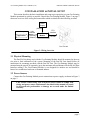
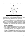
As shown in Figure 1 the Geo-Pointing Module (GPM) accepts commands over the built-in
Ethernet/IP interface. The Geo-Pointing Module connects to the Pan-tilt unit (PTU) Host Interface
(RS-232). Both standard pan-tilt pointing and configuration commands, as well as geo-pointing
commands can be sent to the Geo-Pointing Module. Standard pan and tilt commands are passed
directly to the PTU. Geo-pointing commands are processed by the Geo-Pointing Module to
compute pan-tilt angle commands which it then issues to the attached PTU.
The Geo-Pointing Module must be configured with the position of the pan-tilt unit in geocoordinates (latitude, longitude, altitude, and 3D orientation). The latitude, longitude and altitude
of the pan-tilt unit are entered manually using the Geo-Pointing Module’s web interface (e.g.,
using a hand-held GPS unit to measure the installed pan-tilt unit position).
The built-in calibration function computes the orientation of the pan-tilt in real-world
coordinates using a set of user-provided landmarks. Landmark locations (latitude, longitude,
altitude) are entered through the web interface. The pan-tilt is then aimed at four or more
landmarks and the system automatically computers the pan-tilt’s orientation estimate.
Once calibrated, the Geo-Pointing Module can accept geo-pointing commands and queries.
A set of web pages built into the Geo-Pointing Module allow configuration and control of the
pan-tilt.
Host Computer
Application
IP Network
y
y
Ethernet
(10baseT)
Geo-Pointing
Module
Host
Interface
OR
NS
E
S
NG
MI
AI
Standard pan-tilt commands
Geo-Pointing Commands
Pan-Tilt Unit
Application
Figure 1: Geo-Pointing Module System Overview
Target location
(Lat, Lon, Alt)
Pan/Tilt angles computed
from Geo-coordinates by
GPM
Lat, Lon, Alt, and
Orientation of Pan-Tilt base
defined during installation
or read from sensors
(simplified 2D case)
Figure 2: Geo-Pointing Module Operation
page 3
QUICK START
Geo-Pointing Module User’s Manual (v1.0)
2.2 Installation Components
Components supplied with this manual are:
•
•
•
Geo-Pointing Module (GPM)
Ethernet Patch Cable (crossover type)
AC/DC Power Supply
2.3 Required Components
•
•
•
•
•
Directed Perception Pan-Tilt Unit (PTU-D46-17, PTU-D46-70, or PTU-D300)
Camera or other payload that allows “aiming” the Pan-Tilt Unit at a known landmark
Pan-Tilt Host Serial Cable (to connect GPM to Pan-Tilt unit; supplied with pan-tilt unit)
Host computer with Ethernet connection
Hand-held GPS unit or other means to survey geo-position of installed pan-tilt unit and
landmarks for calibration
2.4 Basic Setup Steps
The following outlines the basic set-up and installation steps. Section 3 on page 5 and
subsequent sections detail each of these steps.
1. Install Pan-Tilt Unit including payload. For calibration, payload must allow visibly identifying what the pan-tilt is pointing at (e.g., camera with a display that allows centering the FOV
on a specific point).
2. Connect Geo-Pointing Module to Pan-Tilt Host Interface.
3. Connect Geo-Pointing Module Ethernet connection to Host Computer and configure GeoPointing Module IP network address.
4. Set the pan-tilt’s position by entering its latitude, longitude, and altitude (e.g., by surveying
with a handheld GPS unit).
5. Calibrate the pan-tilt’s orientation by alternately pointing at, and entering coordinates for, a
minimum of 4 and up to 10 landmarks.
6. Unit is ready to accept geo-pointing commands through the “Geo Control” web page and/or
using the DPoIP command format.
page 4
Geo-Pointing Module User’s Manual (v1.0)
INSTALLATION & INITIAL SETUP
3 INSTALLATION & INITIAL SETUP
This section describes the basic installation and setup steps required to get your Geo-Pointing
Module operational as quickly as possible. Unpack the Geo-Pointing Module. Figure 3 on page 5
shows an overview of the wiring and connections which are detailed in the following sections.
Power
Supply
(12VDC)
Host Computer
Application
LAN
Interface
Ethernet
(10baseT)
Geo-Pointing
Module
PTU
Interface
RS-485
Pan-Tilt Unit
Figure 3: Wiring Overview
3.1 Physical Mounting
The Pan-Tilt Unit being used with the Geo-Pointing Module should be mounted at the user
site prior to final calibration of the system. Mounting of the Pan-Tilt Unit should follow all
instructions for mounting provided with the Pan-Tilt Unit. The Geo-Pointing Module may be
mounted near the pan-tilt, or separately (up to the maximum allowed distance for the RS-485 Host
Interface cabling). The Geo-Pointing Module is not designed for outdoor use and should be
housed in a weatherized enclosure or mounted indoors.
3.2 Power Sources
Connect the Geo-Pointing Module power connections to power supply as shown in Figure 3
on page 5.
CAUTION! When wiring your own power source, failure to comply with
wiring and power source requirements described in this manual can result
in decreased unit performance or damage not covered under the limited
warranty.
page 5
INSTALLATION & INITIAL SETUP
Geo-Pointing Module User’s Manual (v1.0)
3.3 Pan-Tilt Unit Interface Connection and Settings (RS-485)
The Geo-Pointing Module PTU Interface connects to the RS-485 Host Interface on the PanTilt Unit. The Pan-Tilt RS-485 settings must be set to match that of the Geo-Pointing Module:
9600 baud, 1 start bit, 8 data bits, 1 stop bit, and no parity. Hardware handshaking and XON/
XOFF are not used.
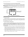
The RS-485 connections to the Geo-Pointing Module are: R+ (pin 2), R- (pin 3), T- (pin 4),
T+ (pin 5) and Sheild (pins 1 and 6). Figure 4 on page 6 shows the connector pinout for the RS485 interface on the Geo-Pointing Module.
1
2
3
4
5
6
Shield
R+
RTT+
Shield
1 2 3 4 5 6
View looking into RJ12
(6P6C) receptacle
Figure 4: Geo-Pointing Module RS-485 Interface
3.4 Ethernet Interface
The Ethernet Interface on the Geo-Pointing Module is an industry-standard RJ-45 connector
and connects to a LAN that is reachable from the Host Computer. For initial configuration this
may be a direct connection between the Host Computer and the Geo-Pointing Module with the
use of an appropriate “cross-over” cable.
3.5 Initial Installation and Operation
Before you can use the Geo-Pointing Module you must configure its IP address so that it can
communicate with the Host Computer and other applications over Ethernet/IP. The Geo-Pointing
Module ships with a default IP address of 192.168.1.110. The computer that is used to initially
configure the IP address of the Geo-Pointing Module must be accessible from the LAN where the
Geo-Pointing Module is installed. Following are the basic steps to install and test operation of the
Geo-Pointing Module.
1. Mount and power Pan-Tilt Unit according to User Manual instructions. Mount payload or
temporary camera and an output device to allow viewing where the Pan-Tilt Unit is pointing
(required for calibration step). [IMPORTANT: sensor should be mounted carefully so that
line-of-sight angle is pointing exactly “forward” with respect to pan-tilt unit. Misalignment
of sensor to pan-tilt will affect system accuracy].
2. Connect an RS-485 cable between the Pan-Tilt Unit RS-485 Host Interface and the GeoPointing Module PTU Interface. Ensure that the PTU Host Interface communications
settings are configured as defined in Section 3.3 on page 6.
page 6
Geo-Pointing Module User’s Manual (v1.0)
INSTALLATION & INITIAL SETUP
3. Connect an Ethernet cable between the Geo-Pointing Module LAN Interface and the LAN
where the Host Computer resides. [IMPORTANT: ensure that there are no other devices on
the LAN at the Geo-Pointing Module Default IP Address, or use a direct connection with
“crossover” cable.]
4. Apply power to the Geo-Pointing Module.
5. On the Host Computer open a web browser and point to “HTTP://192.168.1.110/”. The
Network Configuration web page should appear. If the Geo-Pointing Module cannot be
reached check ethernet connections and reconfigure LAN as required. See Section 5.2 on
page 17 for additional information on configuring the Network address.
6. Click the “PTU Control” web page from the upper navigation bar. Make sure the Pan-Tilt
Unit is powered. Test communication with the Pan-Tilt Unit by clicking on the pan or tilt
arrows or entering a position command. See Section 5.4 on page 19 and Section 5.3 on page
18 for additional information on web configuration control of the Pan-Tilt Unit.
7. Point your browser at the “Geo Config” page (from the upper navigation bar). Enter the
surveyed Pan-Tilt Unit location (latitude, longitude, altitude) using the fields on the “Geo
Config” web page. See Section 5.4 on page 19 for details on Geo Config.
8. Point your browser at the “Geo Calibration” page (accessible from the Geo Config page).
Point the pan-tilt (e.g., using the PTU Control web page) at the first landmark, enter the geocoordinates of the first landmark, and “Save”. Repeat for a minimum of 3 additional
landmarks. Up to 10 landmarks may be entered. See Section 5.5 on page 20 for further
details on calibration. Click “Calibrate”. This operation may take up to several minutes.
9. Point your browser at the “Geo Control” page (from the upper navigation bar). Enter geocoordinates of desired target locations and command the Pan-Tilt Unit to point. See Section
5.6 on page 22 for further details on Geo-Pointing commands.
10. (Optional) Use the DPoIP interface to send calibration and/or pointing commands from a
web browser or custom application. See Section 4 on page 9 for further details on the DPoIP
command interface.
3.6 Resetting to Factory Defaults
The Geo-Pointing Module can be reset to factory defaults (network address parameters) with
the following procedure:
• Depress service pin (see Figure 5 on page 7) and hold for 5 seconds.
This will set IP address, Subnet, Gateway, DNS, Name, Username, Password parameters to
factory default values. It will also erase user values in memory including landmarks and
calibration data.
[Insert photo of service pin]
Figure 5: Geo-Pointing Module Service Pin
page 7
INSTALLATION & INITIAL SETUP
page 8
Geo-Pointing Module User’s Manual (v1.0)
Geo-Pointing Module User’s Manual (v1.0)
COMMAND REFERENCE
4 COMMAND REFERENCE
This section describes the Geo-Pointing Module command set. Each command has a section
that provides a brief functional description, a format (syntax) description, examples, and related
topics. Only commands specific to the Geo-Pointing Module are described here. Standard pan-tilt
commands that may be passed through the Geo-Pointing Module to the Pan-Tilt Unit are
described in the relevant Pan-Tilt Unit User Manual.
When describing the format (syntax) of pan-tilt Geo-pointing commands, the following
conventions are adopted:
• Input characters may be in upper or lower case (we show them in upper case for
presentational consistency)
• A delimiter (<delim>) can be either a space (“ ”) or a carriage return (<CR>).
4.1 DPoIP Command Format
The Geo-Pointing Module accepts both Geo-pointing commands and standard pan-tilt commands
over TCP/IP using HTTP get commands (“DPoIP command format”).
4.1.1 General Forms
The general form of the DPoIP command format is:
Description:
The Geo-Pointing Module accepts both Geo-pointing commands and
standard pan-tilt commands over TCP/IP using HTTP get commands
(“DPoIP command format”).
The “raw” form returns the raw result from the pan-tilt or Geo-Pointing
Module command. The “non” command executes the command but returns
no data.
Syntax
http://<ipaddr>/<verb>?<cmd>=<params><delim> |
http://<ipaddr>/<verb>?cmd=<command><delim>
where
<ipaddr> is the IP Address of the GPM
<verb> ∈ { “non” , “raw” }
<cmd> is a Geo-Pointing or Pan-Tilt command
<command> = <cmd><params>
<params> = “”
| <param1>
| <param1>,<param2>
| <param1>,<param2>,<param3>
Examples
The following commands the pan-tilt to pan to location 42 and tilt to location
99 using the “PP” and “TP” commands, and then resets the pan-tilt. The GeoPointing Module is at IP address 192.168.1.110.
http://192.168.1.110/non?PP=42
http://192.168.1.110/non?TP=99
http://192.168.1.110/non?R
The following commands use alternate forms of the commands to execute the
same “PP” pan-tilt command. The second form is generally more convenient
page 9
COMMAND REFERENCE
Geo-Pointing Module User’s Manual (v1.0)
for sending requests from a web page while the first is more convenient for
programs.
http://192.168.1.110/raw?cmd=PP1200
http://192.168.1.110/raw?PP=1200
http://192.168.1.110/raw?R
4.1.2 Authentication of IP Commands
All DPoIP commands are authenticated using the HTTP “Basic Authentication Scheme”.
The basic authentication scheme provides for filtering unauthorized access to resources on an
HTTP server. It is based on the assumption that the connection between the client and the server
can be regarded as a trusted carrier. As this is not generally true on an open network, the basic
authentication scheme should be used accordingly.
When issuing DPoIP commands to the Geo-Pointing Module from a browser, the user will be
prompted for a user-name and password. A valid user-name and password will allow the
command to be sent to the GPM. User-name/password must be entered once per session (or username/password may be stored by your browser depending on settings).
Non-browser applications must set the credentials (user-name, password) on the GeoPointing Module server prior to issuing each DPoIP command.
The factory-set default username is “admin” and the factory-set default password is
“default” User-name and password are managed from the Network Configuration web page (See
Section 5.2 on page 17).
4.2 Calibration Commands
4.2.1 Calibration & Relevant Terms
Geo-pointing commands operate by translating target geo-coordinates to relative pan-tilt
pointing angles using the known position and orientation of the pan-tilt unit. The pan-tilt unit
position and orientation are defined during a calibration step after the pan-tilt is physically
installed at the site of use.
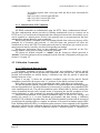
Figure 6 on page 11 shows the orientation coordinate system for the pan-tilt. Pan-tilt
orientation is measured with respect to the “0” positions of pan and tilt positions of the unit.
Pitch offset accounts for any error in mounting the sensor with respect to 0 pitch angle.
The pan-tilt position (latitude, longitude, altitude) of the installed pan-tilt is defined using the
relevant commands below. Pan-tilt position may be measured, for example, using a handheld GPS
at the installed pan-tilt site. The pan-tilt orientation can be defined either by directly entering the
values (determined through some external means of measuring the pan-tilt orientation in realworld coordinates), or, more commonly, by using the calibration function described below.
Automated determination of the pan-tilt orientation angles is achieved by entering, and
pointing the pan-tilt at, 4 or more landmark geo-locations and then issuing a calibration
command. The calibration algorithm then uses the defined landmark locations and the associated
recorded pan-tilt pointing angles to compute an estimate of the pan-tilt orientation angles (Roll,
Pitch, Heading and Pitch Offset). A calibration quality measure is also computed by the algorithm
and can be queried after the calibration function is invoked to determine if additional or different
landmarks produce a more accurate orientation estimate. Calibration quality is computed as a
page 10
Geo-Pointing Module User’s Manual (v1.0)
COMMAND REFERENCE
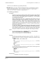
“typical maximum error” in degrees as shown in Figure 7 on page 12. Once pan-tilt position and
orientation are defined, geo-pointing commands may be issued.
Heading
Roll
Pitch
Figure 6: Pan-Tilt Orientation Coordinate System
Overall accuracy of the geo-pointing commands is determined by pointing resolution of the PTU and
accuracy of the initially provided geo-position and orientation of the PTU. For target standoff distances of
greater than ~1000m, angular error of the geo-pointing will approximately equal error in the calibrated
pan-tilt orientation. Careful aiming during calibration, and use of accurately surveyed and well-spaced
landmarks allows overall resolution to approach the angular resolution of the PTU being used.
Accuracy can also be affected by the alignment of the sensor to the pan-tilt frame of reference. Up to
approximately 5 degrees of misalignment between sensor line-of-sight and pan-tilt coordinates will result
in error similar to that of pan-tilt angular error. Misalignment above 5 degrees should be avoided.
Landmarks for calibration should be selected so as to cover a wide span of angles (up to 180 degrees
preferred) and distances. A minimum of 4 landmarks are required to compute PTU orientation. Additional
landmarks can improve system pointing accuracy. Landmarks should also be selected to have a visually
distinct point that can be seen by and aligned to the camera/sensor (e.g., center of field-of-view) during
landmark definition. The survey location of the landmark should match the landmark’s visual alignment
point used during the calibration process.
A “landmark quality” value is output by the calibration algorithm. This value can be used to identify
poorly surveyed or aimed landmarks and provides a good estimate of overall system accuracy.
4.2.2 Tips on Selecting Landmarks
Accurate survey and entry of landmarks is critical to overall system geo-pointing accuracy.
The following guidelines can help ensure the best calibration:
• Select a set of landmarks that cover the widest possible range of angles, distances and
altitudes. Even if the field of interest for operation is narrow, a wider range of landmarks
will help ensure better pointing accuracy. Having some of the landmarks quite far away (> 1
mile) will also help system accuracy.
• Select landmarks which have a visually distinct survey point. When aligning the pan-tilt to
the landmark (e.g., viewing through a zoomed-in camera), it is important to aim at the
surveyed location. Objects like the base of a flagpole or telephone pole, or corner of a
building are usually good. Make sure the landmark will be visible from the mounted pan-tilt
location.
page 11
COMMAND REFERENCE
•
Geo-Pointing Module User’s Manual (v1.0)
Survey carefully. Most hand-held GPS units include an “averaging” function which will
improve measured coordinates if the unit is left in position for a period of time. Using this
function can improve landmark location quality.
Actual Target location
(lat,lon,alt)
Location pointed at by
"KG lat,lon,alt"
Calibration Quality =
(max of this error
across all orientation
angles)
(simplified 2D view)
Figure 7: Calibration Quality Measure
4.2.3 Calibration (geo-reference)
Description:
Specify or query the calibrated position and orientation of the PTU. Current
position can be changed on the fly and will be written to flash each time it is
changed. A maximum of 10 landmarks may be defined for the calibration
algorithm. All heading, roll, and pitch information is in radians.
Syntax
Query calibrated latitude position:
Set calibrated latitude position
Query calibrated longitude position:
Set calibrated longitude position
Query calibrated altitude position:
Set calibrated altitude position
KL<delim>
KL<position><delim>
KO<delim>
KO<position><delim>
KA<delim>
KA<position><delim>
Query calibrated heading position:
Set calibrated heading position
Query calibrated roll position:
Set calibrated roll position
Query calibrated pitch position:
Set calibrated pitch position
Query calibrated pitch-offset position:
Set calibrated pitch-offset position :
KH<delim>
KH<position><delim>
KR<delim>
KR<position><delim>
KP<delim>
KP<position><delim>
KN<delim>
KN<position><delim>
Query landmark locations:
Set calibrated landmark:
Issue calibration command:
Clear last landmark:
page 12
KM<delim>
KM<name>,<lat>,<lon>,<alt><delim>
KC<delim>
KD<delim>
Geo-Pointing Module User’s Manual (v1.0)
Clear all landmarks:
Query calibration quality:
COMMAND REFERENCE
KJ<delim>
KQ<delim>
Example
The following defines the PTU position, defines and points at 4 landmark
locations, computes the calibrated orientation, and queries the resulting
calibration quality.
KL36.67939 *
KO-121.43923 *
KA335 *
A *
KM lm-1, 37.67939, -122.43923, 345 *
<point PTU at landmark using commands such as PO
and TO>
KM lm-2, 35.67939, -123.43923, 355 *
<point PTU at landmark using commands such as PO
and TO>
KM lm-3, 36.67939, -124.43923, 315 *
<point PTU at landmark using commands such as PO
and TO>
KM lm-4, 38.67939, -125.43923, 305 *
<point PTU at landmark using commands such as PO
and TO>
KC *
KQ * Current calibration quality is 0.125 deg.
4.3 Geo-Pointing Commands
The Geo-Pointing Commands allow commanding the Pan-Tilt unit to aim at a given geocoordinate (latitude, longitude, altitude) and to read the geo-coordinate at which the Pan-Tilt Unit
is pointing. These commands are valid only after a calibration has been completed (see Section
4.2 on page 10).
4.3.1 Geo-Coordinate Data Formats
Geo-coordinates used in the pointing and query commands utilize a latitude, longitude, and
altitude coordinate system. Multiple data formats are accepted as input parameters. Geocoordinates returned by the Query functions are in format 1. ASCII data representations for
Latitude (<lat>) and Longitude(<lon>) data for pointing commands are as follows:
1. DDD.ddddd : “DDD” is degrees and “ddddd” is decimal degrees
2. DDD:MM.mmmm : “DDD”=degrees; “MM” = minutes; “mmmm” = decimal minutes
3. DDD:MM:SS.sss : “DDD” = degrees;“MM” =minutes;“SS”=seconds;“sss”=decimal
seconds
The format is flexible with respect to significant digits. So for example, “012.45678” is
interpreted the same as “12.45678”. Negative values must include “-” prefix. Positive values need
not include “+”.
The return format for query functions is always format 1.
Altitude data (<alt>) format is:
aaaaa : “aaaaa” = altitude in Feet. [IMPORTANT: make sure to convert surveyed altitude data
page 13
COMMAND REFERENCE
Geo-Pointing Module User’s Manual (v1.0)
to feet for use in calibration or geo-pointing functions]
IMPORTANT: By convention, latitude and longitude numeric representations are signed
numbers indicating hemisphere. “West” and “South” coordinates are signed negative “-”,
while “East” and “North” coordinates are signed positive “+”.
4.3.2 Position (geo-reference)
Description:
Specify or query the geo-pointing position. Desired positions can be changed
on-the-fly without waiting for previous position commands to complete. PanTilt can be moved using standard pan-tilt commands (e.g., “PP”) and then
geo-pointing position queried.
There are three forms of the “KG” command. One that requires lat, lon, alt
which points the unit at the given coordinates. There are two “query” forms.
The first, “KG<delim>” returns that last geo-coordinate given via a KG
command. The “KG<alt><delim>” form computes the geo-coordinate being
currently pointed at. The results of these two forms will differ, since the
altitude of the “position being pointed at” cannot be computed from geometry
alone due to terrain effects.
The “KG<alt><delim>” command will return the lat/lon position computed
as where the current pointing vector intercepts the earth sphere. If the “alt”
given in the query command is 0, this would be the sea level intercept point.
If the altitude provided is non-zero, then the command returns the lat/lon
intercept of “column” normal to the earth sphere and at that given altitude.
Syntax
Set desired pointing position: KG<lat>,<lon>,<alt><delim>
Query desired pointing position:KG<delim>
Query actual pointing position: KG<alt><delim>
Examples
The following sends the pan-tilt unit to point at 36.67939, -121.43923, 335,
then pans the unit 100 steps, and reads the resulting geo-coordinate being
pointed at:
KG36.67939,-121.43923,335 *
A *
KG * Current desired pointing position is 36.67939,
-121.43923, 335
PO100 *
A *
KG * Current desired pointing position is 36.67002,
-121.43123, 350
The following sends the pan-tilt unit to position 1000, 500 then queries the
geolocation being pointed at (at sea level):
PP1000 *
TP500 *
A *
KG0 * Current actual pointing position is 36.67939,
-121.43923, 0
Related Topics
• Calibration: See Section 4.2 on page 10
page 14
Geo-Pointing Module User’s Manual (v1.0)
COMMAND REFERENCE
4.4 Unit Commands
4.4.1 Default Settings
Description:
View current settings and restore default settings for geo-pointing functions.
Syntax
Load default settings to Flash:
KF<delim>
View Current Settings:
KV<delim>
Example
The following displays the current settings, loads the default settings to
Flash, and then displays those:
KV * Current settings are:......
KF * Default settings restored
KV * Current settings are:......
Related Topics
4.4.2 Restore Network Defaults
Description:
Restore unit network address settings to factory defaults. Use to reconfigure
IP network identity of unit to a known state.
Syntax
Restore Defaults:
KR<delim>
Example
The following restores unit network address parameters to factory defaults:
KR *
4.4.3 Reboot Module
Description:
Reboot the Geo-Pointing Module.
Syntax
Reboot Module:
Example
The following reboots the module:
KK *
KK<delim>
page 15
COMMAND REFERENCE
page 16
Geo-Pointing Module User’s Manual (v1.0)
Geo-Pointing Module User’s Manual (v1.0)
WEB CONTROL INTERFACE
5 WEB CONTROL INTERFACE
The Geo-Pointing Module has a built-in web server and set of password-protected web pages
that allow the user to:
•
•
•
•
•
Configure the Geo-Pointing Module network addresses
Configure and Control the Pan-Tilt Unit
Configure and Calibrate Geo-Pointing Module
Manually Enter Geo-Pointing Commands
Update Geo-Pointing Module firmware
The following sections provide details on use of these web pages.
Once the Geo-Pointing Module is connected to the LAN, an accessible host computer can be
used to access these web pages by pointing a browser at: “http://<gpm-ip>/”. This will bring up
the default “home” page of the unit (“Network Configuration”). The other pages can be accessed
from the top navigation bars accessible from all pages.
5.1 Authentication and Access Control
All web pages are secured via password protection. The HTTP “Basic Authentication
Scheme” is used. The basic authentication scheme provides for filtering unauthorized access to
resources on an HTTP server. It is based on the assumption that the connection between the client
and the server can be regarded as a trusted carrier. As this is not generally true on an open
network, the basic authentication scheme should be used accordingly.
When accessing Geo-Pointing Module web pages, the user will be prompted for a user-name
and password. A valid user-name and password will allow access to the web page. User-name/
password must be entered once per session (or user-name/password may be stored by your
browser depending on settings).
The factory-set default username is [“admin”] and the factory-set default password is
[“default”] User-name and password are managed from the Network Configuration web page
(See Section 5.2 on page 17).
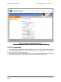
5.2 Network Configuration
This page allows setting of the Geo-Pointing Module’s IP network address and related
parameters. This is the default “home” page of the Geo-Pointing Module.
5.2.1 Accessing the Geo-Pointing Module from the Internet
Once installed, your Geo-Pointing Module is accessible on your local network (LAN). To
access the Unit from the Internet, network routers and firewalls must be configured to allow
incoming traffic over port 80, HTTP. Please refer to the documentation for your router for further
instructions.
5.2.2 Reset Geo-Unit Defaults
The “Reset Geo-Unit Defaults” button on this page will set IP address, Subnet, Gateway,
DNS, Name, Username, Password parameters to factory default values. It will also erase user
values in memory including landmarks and calibration data.
page 17
WEB CONTROL INTERFACE
Geo-Pointing Module User’s Manual (v1.0)
Figure 8: Network Configuration Web Page
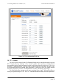
5.3 PTU Configuration
This page allows configuration of many pan-tilt parameters on the Pan-Tilt unit attached to
the Geo-Pointing Module. Refer to the Users Manual for your pan-tilt unit for details on the
semantics and function of these parameters.
The “Restore Factory Defaults” button issues a “DF” command to the pan-tilt unit and resets
all the parameters on the PTU Config page to values queried from the pan-tilt unit.
page 18
Geo-Pointing Module User’s Manual (v1.0)
WEB CONTROL INTERFACE
Figure 9: PTU Configuration Web Page
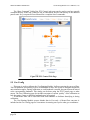
5.4 PTU Control
The Pan-Tilt Unit attached to the Geo-Pointing Module can be controlled manually using the
PTU Control web page. Clicking on the “arrows” graphic allows panning or tilting the unit
incrementally (large or small increments from the large and small arrows respectively). The “Low
Resolution”/”High Resolution” toggle is used to set the increments of the small and large arrows
for incremental pan/tilt movement. “High Resolution” setting will move the pan/tilt smaller
increments per mouse click. The “Low Resolution” will move in relatively larger steps.
The form fields allow entering specific go-to positions. Upon “apply” the pan-tilt will move
to the given position using the “PP” and “TP” commands and the currently set motion parameters.
page 19
WEB CONTROL INTERFACE
Geo-Pointing Module User’s Manual (v1.0)
The “Raw Command” field of the PTU Control web page can be used to send any pan-tilt
command directly to the unit. Whatever text is entered here will be sent directly to the attached
pan-tilt unit. See your pan-tilt Users Manual for a complete list of commands.
Figure 10: PTU Control Web Page
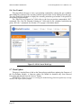
5.5 Geo Config
This page is used to calibrate the Geo-Pointing Module. It allows entering the surveyed PanTilt Unit position, and entering a series of landmarks to allow the system to compute the pan-tilt
unit orientation angles. During calibration, as each landmark is entered, the pan-tilt must be aimed
at the corresponding landmark. This aiming can be done using the PTU Control page or other
means. The Geo Calibration page also includes an output of current “quality” of the calibration to
help determine if more or different landmarks may be required.
A mnemonic label can be associated with each landmark to facilitate identifying it during
calibration.
The Geo-Pointing Module accepts altitude data in Feet only. A Meters/Feet converter is
included on the Geo Config page for convenience in entering surveyed or other geo-coordinates.
page 20
Geo-Pointing Module User’s Manual (v1.0)
WEB CONTROL INTERFACE
Figure 11: Geo Config Web Page
page 21
WEB CONTROL INTERFACE
Geo-Pointing Module User’s Manual (v1.0)
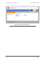
5.6 Geo Control
This page allows the user to issue a geo-pointing command by entering the geo-coordinate
and sending the command. The currently pointed-at geo-location is also displayed on this page.
The page should be refreshed to display the currently pointed-at geo-location if the pan-tilt is
moved using external means.
The “Pan-Tilt Last Targeted At” field refers to the last geo-position commanded (“KG”
command). The “Pan-Tilt Currently Pointing At” field refers to the calculated earth-intercept
point (“KG<alt>” command). See Section 4.3.2 on page 14 for further details.
Figure 12: GEO Control Web Page
5.7 Flash Update
This page is invoked from a link on the Network page and allows updating the firmware of
the Geo-Pointing Module. A firmware update file should be obtained only from Directed
Perception and selected from the “browse” button.
IMPORTANT: Removing power or resetting the module during firmware update may corrupt
memory and require factory repair.
page 22
Geo-Pointing Module User’s Manual (v1.0)
WEB CONTROL INTERFACE
Figure 13: Firmware Update Web Page
page 23
WEB CONTROL INTERFACE
page 24
Geo-Pointing Module User’s Manual (v1.0)
Geo-Pointing Module User’s Manual (v1.0)
CUSTOM CONFIGURATIONS
6 CUSTOM CONFIGURATIONS
The Geo-Pointing Module is specially designed for flexibility and includes a number of
features and options to allow customization and enhancement of the unit for specific applications.
Some of the potential custom configurations and features of the Geo-Pointing Module include:
• Customized web pages
• Gyro/GPS sensor inputs for mobile applications
• Outputs for web control of cameras and other sensors
Contact the Directed Perception Sales Team for details: [email protected]
page 25
CUSTOM CONFIGURATIONS
page 26
Geo-Pointing Module User’s Manual (v1.0)
Geo-Pointing Module User’s Manual (v1.0)
Appendix A.: SPECIFICATIONS
A. SPECIFICATIONS
A.1 Mechanical Dimensions
page 27
Geo-Pointing Module User’s Manual (v1.0)
Appendix A.: SPECIFICATIONS
A.2 Troubleshooting Guide.
A.2.1 Calibrated unit is not pointing to correct locations
Likely Cause: If the position and orientation have not been properly calibrated, the unit will not
point accurately at entered targets.
Remedies: Check the “landmark quality” output for each landmark on the Geo Calibration web
page. This value will often indicate a landmark that is “off” (inconsistent with other landmarks).
This often indicates poor survey data, incorrectly entered coordinates or other error in the landmark data (e.g., was not visually aligned properly during calibration process). Confirm landmark
coordinates, re-align pan-tilt, and re-enter landmark and recalibrate.
A.2.2 “Waiting for Pan-Tilt unit to power up...” will not go away
Likely Cause: The GPM is not able to communicate with the pan-tilt unit.
Remedies: Confirm physical connection between the GPM and the pan-tilt unit. A null-modem
may be required. Confirm that pan-tilt unit baud rate and communications are set at the default
(9600/8/N/1). Make sure Pan-Tilt unit is powered on. If problem persists, power cycle the GPM
after pan-tilt unit is powered on.
A.2.3 Pan-Tilt stopped responding / web page hangs
Likely Cause: The GPM is not able to communicate with the pan-tilt unit.
Remedies: If the pan-tilt had been responding to web commands, and then web commands/web
page queries hang or give http errors, this is likely due to GPM not being able to communicate
with the pan-tilt unit. Try resetting the pan-tilt and GPM units, and reopening browser to the GPM
site.
page 28
REGULATORY INFORMATION
Electromagnetic Interference (EMI) is any signal or emission, radiated in free space or conducted along power or signal leads that endangers the function of a radio navigation or other safety service or seriously degrades, obstructs, or
repeatedly interrupts a licensed radio communications service.
Class A
Class A equipment has been tested and found to comply with the limits for a Class A digital device, pursuant to Part
15 of the FCC Rules. These limits are designed to provide reasonable protection against harmful interference in a
commercial environment. This equipment generates, uses and can radiate radio frequency energy and, if not installed
and used in accordance with the instructions, may cause harmful interference to radio communications. However,
there is no guarantee that interference will not occur in a particular installation. Operation of this equipment in a residential area is likely to cause harmful interference, in which case the user will be required to correct the interference
at his/her own expense.
The Geo-Pointing Module is pending certification for FCC Class A requirements.
Class B
Class B equipment has been tested and found to comply with the limits for a Class B digital device, pursuant to Part
15 of the FCC Rules. These limits are designed to provide reasonable protection against harmful interference in a residential installation. This equipment generates, uses and can radiate radio frequency energy and, if not installed and
used in accordance with the instructions, may cause harmful interference to radio communications. However, there is
no guarantee that interference will not occur in a particular installation. If this equipment does cause harmful interference to radio or television reception, which can be determined by turning the equipment off and on, the user is
encouraged to try to correct the interference by one or more of the following measures:
•
Reorient or relocate the receiving antenna.
•
Increase the separation between the equipment and receiver.
•
Connect the equipment into an outlet on a circuit different from that to which the receiver is connected.
•
Consult the dealer or an experienced radio/TV technician for help.
The Geo-Pointing Module is pending certification for FCC Class B requirements.
Caution: Changes or modifications of this equipment not expressly approved by manufacturer could result in violation of Part 15 of the Federal Communications Commission’s rules. The FCC has prepared the following booklet:
"How to Identify and Resolve Radio-TV Interference Problems.” It is available from the US Government Printing
Office, Washington DC, 20402. Stock Number 004-00-00345-4.
FCC Notice
According to 47CFR, Parts 2 and 15, Class B Computer Peripherals:
This device complies with Part 15 of the FCC Rules. Operation is subject to the following two conditions: (1) This
device may not cause harmful interference, (2) This device must accept any interference received including interference that may cause undesired operations.
page 29
LIMITED WARRANTY
Directed Perception, Inc. warrants this product against defects in material or workmanship, as
follows:
For a period of one year from date of purchase, Directed Perception, Inc. will repair the defective
product and provide new or rebuilt replacements at no charge. Warranty repairs require the
issuance of a repair authorization number from Directed Perception prior to the return of
merchandise, and buyer assumes responsibility for freight charges.
After the one year period, buyer must pay for all parts, labor and freight.
This warranty does not cover any damage due to accident, misuse, abuse or negligence. Buyer
should retain original bill of sale as evidence of the date of purchase.
REPAIR OR REPLACEMENT AS PROVIDED UNDER THIS WARRANTY IS THE
EXCLUSIVE REMEDY OF THE PURCHASER. DIRECTED PERCEPTION SHALL NOT BE
LIABLE FOR ANY INCIDENTAL OR CONSEQUENTIAL DAMAGES FOR BREACH OF
ANY EXPRESS OR IMPLIED WARRANTY ON THIS PRODUCT, EXCEPT TO THE
EXTENT PROHIBITED BY APPLICABLE LAW, ANY IMPLIED WARRANTY OF
MERCHANTABILITY OR FITNESS FOR A PARTICULAR PURPOSE ON THIS PRODUCT
IS LIMITED IN DURATION TO THE DURATION OF THIS WARRANTY.
Some states do not allow the exclusion or limitation of incidental or consequential damages, or
allow limitations on how long an implied warranty lasts, so the above limitations or exclusion
may not apply to you. This warranty gives you specific legal rights, and you may also have other
rights which vary from state to state.
page 30