1
77
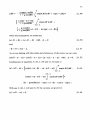
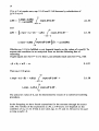
approximately 2 % for the maximum obtainable mechanica! output power of the
motor.
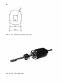
Only experiments with different rotors wil! provide an answer to the question of
which cross-section of the rotor is optima! for a given cross-section of the shaft,
because the losses in the shaft cannot easily be calculated (see the discussion at
the end of section 2.3).
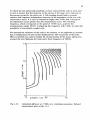
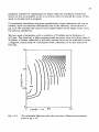
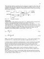
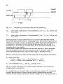
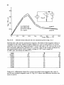
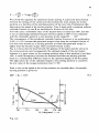
The airgap between the rotor and stator poles is t 00 µm. A decrease of the gap
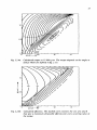
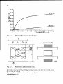
will give a faster rise from i =0 for the <I> line at 6 = 0 in fig. 6.1.1. The area
between the two <I> lines increases, leading to a higher value of the maximum
obtainable mechanica! output power. However one should find an optimum
between the price to be paid for the decreased clearance and the increased output
power.
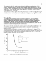
- We note that the inftuence of the decreased gap diminishes when saturation
occurs in the iron parts of the circuit, because then the magnetic resistance of the
iron will dominate.
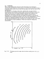
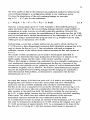
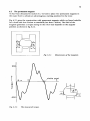
In our design we have chosen the same width for the rotor and the stator poles
(18 mm). The result in our configuration is a fairly sinusoidal relation between the
flux and the rotor position at a fixed current. We note that this relation mainly
determines the torque production and the current carried by the coils as a
function of time.
In our motor the value of the tooth-width/tooth-pitch ratio is 0.38. In ref. [16) a
ratio of 0.35 ... 0.42 is given as optimum for the torque production. However
these values relate to the statie torque production in stepping motors, which have
a large number of teeth per pole. As far as we know, nothing has been reported in
the literature on the optimum relation between the flux linkage, rotor position
and current with respect to the torque production and efficiency of the reluctance
motor. A further study of this aspect is desirable.
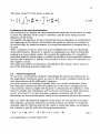
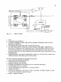
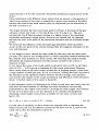
In the reluctance motor we distinguish the bifilar-wound main and catch coils; the
coils have the same number of windings and their resistances are inversely
proportional to the copper cross-section. Choosing the same copper cross-section
for the wire of both coils is not the optimum if we consider the dissipation.
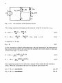
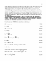
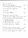
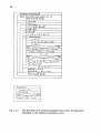
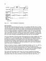
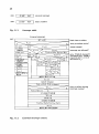
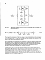
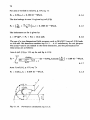
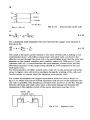
Assuming a fixed copper cross-section available for two coils, we have (see
fig. 6.1.12):
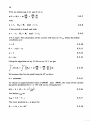
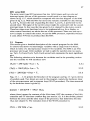
Acu
= Acu,m + Acu,c = a Acu + (1
- a) Acu·
6.1.10
For the sake of simplicity we have drawn two separate coils to represent the
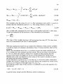
bifilar-wound coils. Let the effective current for the main coil be Im and for the
catch coil Ic, then the dissipation is given by:
P(:)
_!L + I~
Acu,m
Acu,c
6.1.11