1
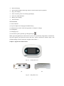
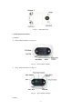
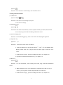
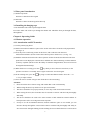
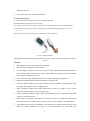
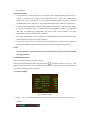
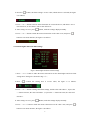
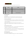
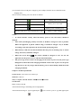
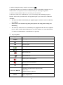
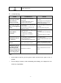
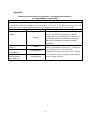
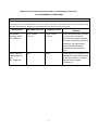
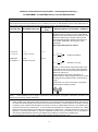
Visual Electronic Stethoscope I USER NOTICE Announce This user manual is written and compiled in accordance with the council directive MDD93/42/EEC for medical devices and harmonized standards. This user manual includes special documents, which under protection of copyright law. All rights reserved. Without written announcement from our company, the user manual should not be transferred, copied or translated into other language. Owing to the forthcoming renovation or error contained in the manual, the specific products you received may not be totally in accordance with the description of this User Manual. We would sincerely regret for that. The User Manual is published by our company. All rights reserved. Manufacturer's responsibility Our company is responsible for safety, reliability and performance of this equipment only in the condition that: All assembly operations, expansion, change, modification and repairs are conducted by persons authorized by our company. The device is operated under strict observance of this manual. Warning: This device is not intended for treatment. If the result is distrustful, please use other methods to verify immediately. Warranty The unit can not be repaired by users themselves. All services must be done by the engineers approved by manufacturer. We warrant that each product we sell you is free from defects in labour and materials and shall conform to its product specifications as defined in the user doc umentation. If the product doesn't function as warranted during the warranty period, we will repair or replace it without charge. Misuse, improper maintenance may void the warranty. Label presentation Warning: the information that should be noted to avoid injury to the patient and the operator. Attention: important information that you should know. II CONTENT Chapter1SafetyGuidance ............................................................................................................... 1 1.1Safetyoperationexplaining ............................................................................................................... 1 1.2Warning ........................................................................................................................................... 1 1.3Attention .......................................................................................................................................... 1 Chapter2Briefintroduction............................................................................................................. 2 2.1Overview ......................................................................................................................................... 2 2.2ApplicableRange ............................................................................................................................. 2 2.3Features ........................................................................................................................................... 2 2.4Mainperformance ............................................................................................................................ 2 2.5Accessories ...................................................................................................................................... 3 Chapter3AppearanceandStructure ............................................................................................... 3 3.1Frontpanelintroduction .................................................................................................................... 4 3.2Sidepanelsintroduction .................................................................................................................... 5 3.3Rearpanelintroduction ..................................................................................................................... 6 3.4Installingthehangingrope ................................................................................................................. 6 Chapter4OperatingGuide ...................................................................................................................... 6 4.1Monitoroperation ............................................................................................................................. 6 4.1.1AuscultationandECGmonitor ....................................................................................................... 6 4.2MenuOperation................................................................................................................................ 8 4.3AlarmOperation ............................................................................................................................. 10 4.4Chargingoperation ......................................................................................................................... 10 Chapter5Productspecification ..................................................................................................... 11 Chapter6Cleaning、MaintenanceandDisinfecting .................................................................... 13 6.1Cleaning ........................................................................................................................................ 13 6.2Disinfecting ................................................................................................................................... 13 6.3Maintenance .................................................................................................................................. 13 7.KeyofSymbols ............................................................................................................................. 14 8.TroubleShooting ......................................................................................................................... 15 Appendix ........................................................................................................................................ 16 III Chapter 1 Safety Guidance 1.1Safety operation explaining This unit is internally powered equipment; the degree of shock protection is type B applied part . Type B applied part protection means that these patient connections will comply with permitted leakage currents, dielectric strengths of IEC 60601-1. To avoid any possible danger, please operate the device according to safety guidance as following: 1.2 Warning The infrared is harmful to the eyes, so the user and the maintenance man should not stare at the light part of the SpO2 probe (the infrared is invisible). The SpO2 probe can not be clipped on the edema and tender tissue. Please don't use this device when charging. Explosive hazard—DO NOT use the device in environment with inflammable gas such as some ignitable anesthetic. Please don't use this device when MRI or CT scanning. The person who is allergic to rubber can not use this device. The user must use the oximeter probe which is provided by our company, don't use the parts which are not manufactured by our company. The device don't suit all user,if you can't get steady value, please stop using it. This device is not intended for treatment. The device can not be transported mixed with toxic, harmful, corrosive material. 1.3 Attention Please check the packing before use to make sure the device and accessories are totally in accordance with the packing list, or else the device may have the possibility of working abnormally. The device may be a little different from the picture of manual, please make actual device as standard. Before using, check the main unit and all accessories periodically to make sure that there is no visible damage that may affect patient's safety and performance. It is recommended that the device should be inspected once a month at least. When there is obvious damage, stop using the device before changing the damaged parts. Necessary maintenance must be performed by qualified service engineers only. Users are not permitted to maintain it by themselves. The device is designed for continuous operation and is 'ordinary'. If the device gets wet, please stop operating it. Keep the device away from dust, vibration, corrosive substances. Electromagnetic Interference-Ensure that the environment in which the device is 1 operated is not subject to any sources of strong electromagnetic interference , such as MRI scan, mobile telephones, etc. Keep them far away. Since the friction of body or clothes will bring high voltage static, and interfere the veracity of the tested data by the apparatus, it is avoided to be used in the environment of high voltage static. Please don't measure this device with functional tester for the device's related information. When it is carried from cold environment to warm or humid environment, please do not use it immediately. DO NOT operate keys on front panel with sharp materials. When cleaning and sterilization, please refer to user manual related chapters for details. The disposal of scrap instrument and its accessories and packings (including battery, plastic bags, foams and paper boxes) should follow the local laws and regulations. The device has normal useful life for three years since the first electrified use. After the service life, please return the products to the manufacture or disposal the products according to local regulations. Please refer to text for else notice proceeding. Chapter 2 Brief introduction 2.1 Overview Visual electronic stethoscope is integrated with functions of electronic stethoscope, cardiogram and pulse perimeter. It takes the latest sensor technology to monitor human's Heart Sound and Lung Sound, whose volume can be adjusted, and it also adds functions like cardiogram , heart rate and pulse oximeter display etc. The device uses color LCD of high resolution to display the real-time cardiograph, and figure out the HR according to the cardiograph to help the doctor diagnose in time. 2.2 Applicable Range The product is applicable for family, hospital, oxygen station,community medical treatment, sport health care (it is advised to be used before and after sport, and it is not advised to be used in the process of sport) and so on. 2.3 Features Operation of the product is simple and convenient, display is exact and in real time. Light weight, small size, easy to carry. Low power consumption. Multi-function, know more physiological information. 2.4 Main performance Three-mode choices: heart sound mode, lung sound mode and combination mode ECG waveform display 2 Heart rate display SpO2 monitor through connecting with an external oximeter probe (optional) SpO2 value display Pulse waveform, pulse rate and bar graph display Pulse rate sound indication Battery power display Alarm function 2.5 Accessories (1) A User Manual (2) A power adapter (for charging the lithium battery) (3) A data line (be used to connect the apparatus to computer to charge) (4) An Earphone (5) A hanging rope (6) An oximeter probe (optional, type BF applied part ) Note: Type BF applied part means that the device has specifically safeguard for electroshock. Type BF applied part protection means that these patient connections should comply with permitted leakage currents, dielectric strengths of IEC 60601-1. Chapter 3 Appearance and Structure Fig. 3-1 Front panel view (a) (b) Fig.3-2 Side panels view 3 Fig.3-3 Rear panel view 3.1 Front panel introduction (1) Display ECG monitor interface is as Fig.3-4: Fig.3-4 ECG monitor interface SpO2 monitor interface is as Fig.3-5: Fig.3-5 SpO2 monitor interface (2) Keys 4 Symbol : Function : Press the "Power switch" long to turn on/off the device. 3.2 Side panels introduction (1) USB Socket Symbol: %SpO2 / Function: 1.The socket for connecting SpO2 probe 2.The socket for charge (2) Earphone Socket Symbol: Function: In the mode of auscultation, cut in the earphone which is provided, and auscultate heart sound, lung sound and heart&lung combination sound. (3) Hole for hanging rope Function : Connect the hanging rope, and it is convenient for schleping the apparatus. (4) Adjustable key Symbol: ━ ╋ Function: 1. Control the volume in the auscultation. 2. In the auscultation, keep pressing the buttons "-" and "+" to enter DEMO mode. Display normal ECG wave, and press the two buttons again to make the wave renew. 3. In the interface of SpO2 , operate according to the menu. (see chapter 4.2) 4. Operation of alarm function shortcut key. (see chapter 4.3) (5) Menu key Symbol: Function: 1. In the auscultation, switch among heart sound, lung sound and combination sound. 2. When testing ECG wave, press the button to congeal the wave and it is easy to observe; press it again to cancel congeal and the wave will renew. 3. In the interface of SpO2 , operate according to the menu. (see chapter 4.2) 5 3.3 Rear panel introduction (1) Stethoscope Probe Function: Collect heart-beat signal. (2) Electrode Function: Collect electrical signal of the body. 3.4 Installing the hanging rope A. Put the thinner side of the rope through the hole. B. Put the wider side of the rope through the thinner side which has been put through the hole, then tighten it. Chapter 4 Operating Guide 4.1 Monitor operation 4.1.1 Auscultation and ECG monitor (1) Let the patient lying down. (2) Daub some medical conductive paste to the surface of the three electrodes well-proportioned. (see Fig.3-3) (3) Press the power switch long to turn on the device, and it will enter into the ECG measurement interface (do not connect the oximeter probe to the device). (see Fig. 3-4) (4) Hold the main unit and stick to the chest of patient. All the electrodes should stick to the skin upon heart. It can display the real-time ECG and heart rate while monitoring each auscultation section by earphone (the device has the ability of automatic magnification, ECG waveform can be magnified automatically). (5) When the device is testing, press the " "key shortly to freeze the ECG waveform, so the operator can observe it carefully. Press it again to show the waveform again. (6) In the working state, press the " "key long to switch auscultation modes. Press the "-" or "+" key to adjust volume. (7) Press the "Power switch" Long to turn off the device after measuring. Attention: Please check the device before using, and confirm that it can work normally. When testing the ECG, keep the device in quiet environment. The device should be in a proper position, or else it may result in inaccurate measure. When testing the ECG, the electrodes must be assured to connect with the body thoroughly and stably. The device should not be used at the same location or limb which has arterial catheter or blood pressure cuff or receiving intravenous injection. If only to use the auscultation function, medical conductive paste is not needed, you can measure directly through the sensor which connects with the body thoroughly and stably. It also can measure through clothing, but the clothing do not too thick otherwise it will result in 6 inaccurate measure. Acute sport may affect the measure precision. 4.1.2 SpO2 measurement (1) Connect the oximeter probe to the device through USB socket. (2) Put the finger into the probe. (see Fig. 4-1) (3) Press the "Power switch" long to open the device, it will enter the SpO 2 measurement interface. (4) Under measuring interface, the user could read the correlative data from display screen. (see Fig. 3-5) (5) Press the "Power switch" Long to turn off the device after measuring. Fig. 4-1 Finger position (Actual probe may be different with the probe as Fig. 4-1, please accept the actual probe with the device) Attention: The fingernails of the testee should not be too long. Testee can not use enamel or other makeup. As to the fingers which are too thin or too cold, it would probably affect the normal measure of the patients' SpO2 and pulse rate, please clip the thick finger such as thumb and middle finger deeply enough into the probe. Do not shake the finger and keep the patient in a stable state during using process. Fingernails and the luminescent tube should be on the same side. Excessive ambient light may affect the measuring result. It includes fluorescent lamp, dual ruby light, infrared heater, direct sunlight and etc. There shouldn't be rubber fabric and so light barrier on the way of light, or else it it may result in inaccurate measure of SpO2 and pulse rate. If some abnormal conditions appear on the screen during test process, pull out the finger and reinsert to restore normal use. Please read the measured value when the waveform on screen is equably and steady-going, this measured value is optimal value. And the waveform at the moment is the standard one. The problem of overrating would display when the patient is suffering from toxicosis which caused by carbon monoxide, the device is not recommended to be used under this 7 circumstance. Clinical restrictions: As the measure is taken on the basis of arteriole pulse, minimal pulsating blood flow of subject is required. For a subject with weak pulse due to shock, low ambient/body temperature, major bleeding, or use of vascular contracting drug, the SpO2 waveform (PLETH) will decrease. In this case, the measurement will be more sensitive to interference. For those with a substantial amount of staining dilution drug (such as methylene blue, indigo green and acid indigo blue), or carbon monoxide hemoglobin (COHb), or methionine (Me+Hb) or thiosalicylic hemoglobin, and some with icterus problem, the SpO2 determination by this monitor may be inaccurate. The drugs like dopamine, procaine, prilocaine, lidocaine and butacaine may also be a major factor blamed for serious error of SpO2 measure. As the SpO2 value serves as a reference value for judgement of anemic anoxia and toxic anoxia, some patients with serious anemia may also report good SpO2 measurement. Notice: For the particular content of clinic restrict and taboo disease, please read the correlated iatrology literature. 4.2 Menu Operation Menu operation is mainly in the SpO2 interface: In the SpO2 measurement interface, press the button " ", the menu interface (as Fig. 4-2 ) will appear. Users can turn on or turn off alarm function, and set up the higher and lower limit alarm value. The settings means are as follows: 4.2.1 Alarm Settings Fig. 4-2 alarm settings a.Press "-" or "+" button to make the menu selection bar on the "Alarm" item, the figure is as follows: ; 8 " button, the alarm setting is reverse video, which show it is selected, the figure b.Press the " is as follows: ; c.Press "-" or "+" button to choose if the alarm turn on or turn off forever, and choose "on" to turn on forever, or else choose "off" to turn off forever. " button, make the settings display normally. d.After settings are over, press " e.Press "-" or "+" button to make the menu selection bar on the "Exit" item, and press " " button to exit menu interface, the figure is as follows: ; 4.2.2 Alarm higher and lower limit settings Fig.4-3 alarm higher and lower limit settings a.Press "-" or "+" button to make the menu selection bar on the alarm higher and lower limit settings item (the figure is showed as Fig.4-3); b.Press " " button, the setting item is reverse video, the figure is as follows: ; c.Press "-" or "+" button to change the alarm settings, and the value will reduce 1, if press the "-" button one time, the value will reduce 1; if press the "+" button one time, the value will increase 1. d.After settings are over, press " " Button, make the settings display normally. e.Press "-" or "+" button to make the menu selection bar on the "Exit" item, and press " button to exit menu interface, the figure is as follows: 9 " ; The Fig.4-1 is the setting value range of the alarm higher limit and lower limit: Number Function Explain 1 SpO2 value alarm higher limit Setting value range: 0~100, leave factory value 99 (unit: %) 2 SpO2 value alarm lower limit Setting value range: 0~100, leave factory value 85 (unit: %) 3 PR value alarm higher limit Setting value range: 0~254, leave factory value 120 (unit: bpm) 4 PR value alarm lower limit Setting value range: 0~254, leave factory value 40 (uni: bpm) 5 Exit Exit alarm settings menu 4.3 Alarm Operation 4.3.1 Alarm PRI: Alarm include the tested value exceed the limit alarm, low voltage alarm, finger out alarm. Alarm PRI: low voltage alarm > finger out alarm = the tested value exceed the limit alarm. 4.3.2 Alarm recognised methods: (1) Low voltage alarm: battery power is draining away and flashing incessantly. When the battery power is not enough for supplying the apparatus normal work, the screen shows "Low Power" and turn off automatically; (2) Finger out alarm: sound alarm and at the same time the screen shows "Finger Out"; (3) Except for above sound alarm, the others are considered as the tested value exceed the limit alarm. 4.3.3 Alarm shortcut key operation: (1) In the SpO2 operation interface, press the "+" key to turn off the pulse sound indication forever and press the "+" key again to turn on the sound indication forever. (2) In the SpO2 operation interface, if turn on the alarm function in the menu, when the tested value exceed the limit which will lead to alarm, press the "-" key to intermit alarm. Alarm function will renew automatically after 60 seconds more or less. 4.4 Charging operation There are two kinds of charging methods: (1) Connect the device with computer by USB, then the device should be under charging state. 10 (2) Connect the device with power supply by power adapter, then the device should be under charging state. The five status of battery power are shown as follows: Battery power is full Battery power is not full Battery power is draining away The four status above shows dynamically in turn Battery is under charging Notice: To ensure measure exactly, when the battery power is low, the battery should be charged. After battery discharging entirely each time, it should be charged as soon as possible. When the apparatus is placed without using, it should be charged every 6 months. According to the rules operation, the use life will be prolonged greatly. When battery is full, use less than 30 minutes that the power is draining away or cannot charge, the bettery should be changed. When the screen shows , the bettery should be charged at once. Or else the apparatus test the power is low, it will turn off automatically. The power sign revolve when it is charging. In the status of power off, the power sign idisappeared, which show that charging is finished. In the status of power on, the power sign doesn't revolve any longer, and the battery power is showed fully, which show that charging is finished. Chapter 5 Product specification Product Name: Visual Electronic Stethoscope. Model No: CMS-VE Safety: Complies with IEC 60601-1:1988+A1:1991+A2:1995 Classification: EMC: Group I Class B. Anti-electroshock Type: Internally powered equipment. Anti-electroshock Degree: type B applied part . (The oximeter probe is type BF applied part ) 11 Harmful Liquid Proof Degree: IPX1. Degree of Safety in Presence of Flammable Gases: Equipment not suitable for use in presence of flammable gases. Working System: Continuous running equipment. Physics characteristic: Size: 57(L)mm×32(W)mm×30(H)mm Weight: about 50g (including battery) Environment requirements (1) Storage and Transportation Environment: a)Temperature : -10℃~+50℃ b)Relative Humidity: 10%~95% c)Atmospheric pressure range : 50kPa~106kPa (2) Operating Environment: a)Temperature : 5℃~40℃ b)Relative Humidity: 20%~80% c)Atmospheric pressure range: 70 kPa~106 kPa Battery type: charging lithium battery Working-voltage: 3.6 V DC ~ 4.2V DC Power: ≤100mA OLED display: 65K color LCD display; Main Parameters: (1) Measurement of Heart Rate Measurement range: 30 bpm~300 bpm Resolution: ±1 bpm Accuracy: ±2 bpm Display mode: 3 bit LCD numeral display (2) Measurement of SpO2 Measurement range: 35%~100% Resolution: 1% Accuracy: When the SpO2 measurement range is 70%~100%, the permission of absolute error is ±2%; below 70% unspecified Display mode: 2 bit LCD numeral display (3) Measurement of pulse rate Measurement range: 30 bpm~250 bpm Resolution: 1 bpm 12 Accuracy: ±2 bpm or ±2% (select larger) Display mode: 3 bit LCD numeral display PR intensity: continuing bar graph display, the bar graph is higher,and the PR is stronger. (4) Measurement Performance in Weak Filling Condition: SpO2 and pulse rate can be shown correctly when pulse-filling ratio is 0.4%. SpO2 error is ± 4%, pulse rate error is ±2 bpm or ±2% (select larger). (5) Resistance to surrounding light: The deviation between the value measured in the condition of man-made light and indoor natural light and that of darkroom is less than ±1%. Chapter 6 Cleaning、Maintenance and Disinfecting 6.1 Cleaning Keep the outside surface of the device clean and free of dust and dirt, and clean exterior surface of the device (including LCD screen) with a dry, soft cloth. If necessary, clean the chassis with a soft cloth soaked in a solution of soap or water, and wipe dry with a clean cloth immediately. Attention: Before cleaning, switch off the power. Don't use strong solvent, such as acetone. Never use an abrasive such as steel wool or metal polish. The temperature of the water which is used for cleaning the device should be below 60°C. Do not allow any liquid to enter the product, and do not immerse any parts of the device into any liquids. Avoid pouring liquids on the device while cleaning. Don't remain any cleaning solution on the surface of the device. 6.2 Disinfecting After cleaning the device, wipe the surface of device with ethanol, self-air dry (or clean with a clean, dry cloth). Attention: Never try to sterilize the equipment by low temperature steam or high temperature sterilizing process. Do not use E-beam or gamma radiation sterilization or other methods. 6.3 Maintenance The user must check that the equipment does not have visible evidence of damage that may affect patient safety or device capability before using. The recommended inspection interval is once per month or less. If damage is evident, replacement is recommended before using. The device is frangible and must be handled with care. These methods will prolong the life of the unit. 13 (1) Please recharge the battery when the screen shows . (2) Recharge the battery soon after the over-discharge. The device should be recharged every six months when it is no regular used. It can extend the battery life following this guidance. (3) Please clean and disinfect the device after using to avoid infection. (4) The device needs to be calibrated once a year (or according to the calibrating program of hospital). It also can be performed at the state-appointed agent or just contact us for calibration. Attention: The device should be maintained by the eligible engineers who have been accredited by our company. If the device is not used for a long time, please put it in the casing after cleaning and disinfecting. The accuracy of the device is controlled by the equipment and can not be adjusted by user. If the result is distrustful, please use other methods to verify immediately or contact local distributor or manufacture to get help. 7. Key of Symbols Signal %SpO2 Description Pulse oxygen saturation (%) PR Pulse rate (bpm) HR Heart rate (bpm) Full-voltage Low-voltage Alarm-sound "Off" Alarm-sound "On" Close the pulse sound indication Open the pulse sound indication SN And IPX1 Serial number 1. The finger clip falls off (no finger inserted) 2. Probe error 3. Signal inadequacy indicator Ingress of liquids rank 14 WEEE (2002/96/EC) 8. Trouble Shooting Trouble Possible Reason Solution 1.The SpO2 and Pulse Rate can not be displayed normally 1. The finger is not properly positioned. 2. The patient's SpO2 value's going beyond the limits. 1. Place the finger properly and try again. 2. Try again; Go to a hospital for a diagnosis if you are sure the device works all right. 2.The SpO2 and Pulse Rate are not displayed stably 1. The finger is not placed inside deep enough. 2. The finger is shaking or the patient is moving. 1. Place the finger properly and try again. 2. Let the patient keep still. 3.ECG display astatically 1. Electrodes do not connect with skin very well. 2. The device is shaking. 3. The patient is shaking or moving. 1. Recoat gel and press electrodes. 2. Keep the device on the body still. 3. Keep the patient in a stable state. 4.The device can not be turned on 1. The battery is drained away or almost drained away. 2. The malfunction of the device. 1. Recharge battery. 2. Please contact the local service center. 5.Noise Here is disturbance sources. Remove the disturbance sources and other electrical instruments. 6.The device can not be used for full time after charge or the battery can not be full charged even after 10 hours charging time. The battery is broken. Please contact the local service center. Note: If the trouble is still not got rid of, please contact warrant service agent as soon as possible. For the damage aroused by client dismantling and mending, our company does not assume any responsibility. 15 Appendix Guidance and manufacture’s declaration – electromagnetic emissionsfor all EQUIPMENT and SYSTEMS Guidance and manufacture’s declaration – electromagnetic emission The CMS-M Multi-functional Visual Stethoscope & CMS-VE Visual Electronic Stethoscope is intended for use in the electromagnetic environment specified below. The customer of the user of the CMS-M Multi-functional Visual Stethoscope & CMS-VE Visual Electronic Stethoscope should assure that it is used in such and environment. Emission test Compliance Electromagnetic environment – guidance Group 1 The CMS-M Multi-functional Visual Stethoscope & CMS-VE Visual Electronic Stethoscope uses RF energy only for its internal function. Therefore, its RF emissions are very low and are not likely to cause any interference in nearby electronic equipment. RF emissions CISPR 11 RF emission CISPR 11 Harmonic emissions IEC 61000-3-2 Voltage fluctuations/ flicker emissions IEC 61000-3-3 The CMS-M Multi-functional Visual Stethoscope & Class B CMS-VE Visual Electronic Stethoscope is suitable for use in all establishments, including domestic Not applicable establishments and those directly connected to the public low-voltage power supply network that supplies buildings used for domestic purposes. Not applicable 16 Guidance and manufacture’s declaration – electromagnetic immunity – for all EQUIPMENT and SYSTEMS Guidance and manufacture’s declaration – electromagnetic immunity The CMS-M Multi-functional Visual Stethoscope & CMS-VE Visual Electronic Stethoscope is intended for use in the electromagnetic environment specified below. The customer or the user of CMS-M Multi-functional Visual Stethoscope & CMS-VE Visual Electronic Stethoscope should assure that it is used in such an environment. Immunity test IEC 60601 test level Compliance level Electromagnetic environment - guidance Electrostatic discharge (ESD) IEC 61000-4-2 6 kV contact 8 kV air 6 kV contact 6 kV air Floors should be wood, concrete or ceramic tile. If floor are covered with synthetic material, the relative humidity should be at least 30%. the manufacturer may recommend the ESD precautionary procedures to user. Power frequency (50Hz) magnetic field IEC 61000-4-8 3A/m 3A/m Power frequency magnetic fields should be at levels characteristic of a typical location in a typical commercial or hospital environment. 17 Guidance and manufacture’s declaration – electromagnetic immunity – for EQUIPMENT and SYSTEMS that are not LIFE-SUPPORTING Guidance and manufacture’s declaration – electromagnetic immunity The CMS-M Multi-functional Visual Stethoscope & CMS-VE Visual Electronic Stethoscope is intended for use in the electromagnetic environment specified below. The customer or the user of CMS-M Multi-functional Visual Stethoscope & CMS-VE Visual Electronic Stethoscope should assure that it is used in such an environment. Immunity test IEC 60601 test level Compliance level Electromagnetic environment - guidance Portable and mobile RF communications equipment should be used no closer to any part of the CMS-M Multi-functional Visual Stethoscope & CMS-VE Visual Electronic Stethoscope, including cables, than the recommended separation distance calculated from the equation applicable to the frequency of the transmitter. Recommended separation distance Conducted RF 3 Vrms IEC 61000-4-6 150 kHz to 80 MHz Radiated RF 3 V/m IEC 61000-4-3 80 MHz to 2.5 GHz 3 Vrms 3.5 d P E1 80 MHz to 800 MHz 7 d P E1 800 MHz to 2.5 GHz 3 V/m Where P is the maximum output power rating of the transmitter in watts (W) according to the transmitter manufacturer and d is the recommended separation distance in metres (m). Field strengths from fixed RF transmitters, as a determined by an electromagnetic site survey, should be less than the compliance level in each frequency b range. Interference may occur in the vicinity of equipment marked with the following symbol: NOTE 1 At 80 MHz and 800 MHz, the higher frequency range applies. NOTE 2 These guidelines may not apply in all situations. Electromagnetic propagation is affected by absorption and reflection from structures, objects and people. a Field strengths from fixed transmitters, such as base stations for radio (cellular/cordless) telephones and land mobile radios, amateur radio, AM and FM radio broadcast and TV broadcast cannot be predicted theoretically with accuracy. To assess the electromagnetic environment due to fixed RF transmitters, an electromagnetic site survey should be considered. If the measured field strength in the location in which the CMS-M Multi-functional Visual Stethoscope & CMS-VE Visual Electronic Stethoscope is used exceeds the applicable RF compliance level above, the CMS-M Multi-functional Visual Stethoscope & CMS-VE Visual Electronic Stethoscope should be observed to verify normal operation. If abnormal performance is observed, additional measures may be necessary, such as reorienting or relocating the CMS-M Multi-functional Visual Stethoscope & CMS-VE Visual Electronic Stethoscope. b Over the frequency range 150 kHz to 80 MHz, field strengths should be less than 3 V/m. 18 Recommended separation distances between portable and mobile RF communications equipment and the EQUIPMENT or SYSTEM – for EQUIPMENT or SYSTEM that are not LIFE-SUPPORTING Recommended separation distances between portable and mobile RF communications equipment and the CMS-M Multi-functional Visual Stethoscope & CMS-VE Visual Electronic Stethoscope The CMS-M Multi-functional Visual Stethoscope & CMS-VE Visual Electronic Stethoscope is intended for use in an electromagnetic environment in which radiated RF disturbances are controlled. The customer or the user of the CMS-M Multi-functional Visual Stethoscope & CMS-VE Visual Electronic Stethoscope can help prevent electromagnetic interference by maintaining a minimum distance between portable and mobile RF communications equipment (transmitters) and the CMS-M Multi-functional Visual Stethoscope & CMS-VE Visual Electronic Stethoscope as recommended below, according to the maximum output power of the communications equipment. Separation distance according to frequency of transmitter Rated maximum output (m) power of transmitter 150 kHz to 80 MHz 80 MHz to 800 MHz 800 MHz to 2.5 GHz (W) 3.5 d P V1 3.5 d P E1 7 d P E1 0.01 0.117 0.117 0.233 0.1 0.369 0.369 0.738 1 1.167 1.167 2.333 10 3.689 3.689 7.379 100 11.67 11.67 23.33 For transmitters rated at a maximum output power not listed above, the recommended separation distance d in metres (m) can be estimated using the equation applicable to the frequency of the transmitter, where P is the maximum output power rating of the transmitter in watts (W) according to the transmitter manufacturer. NOTE 1 At 80 MHz and 800 MHz, the separation distance for the higher frequency range applies. NOTE 2 These guidelines may not apply in all situations. Electromagnetic propagation is affected by absorption and reflection from structures, objects and people. 19