1
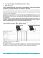
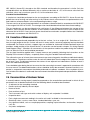
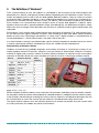
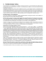
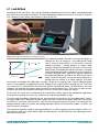
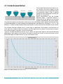
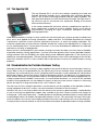
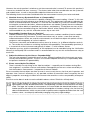
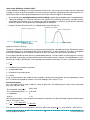
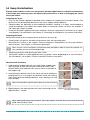
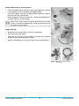
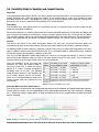
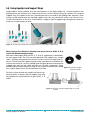
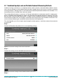
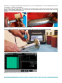
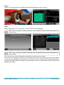
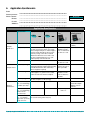
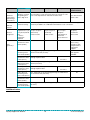
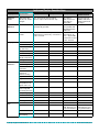
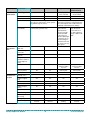
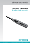
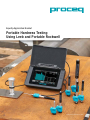
Equotip Application Booklet Portable Hardness Testing Using Leeb and Portable Rockwell Swiss Precision Since 1954 Table of Contents 1.Introduction.............................................................................................. 3 2. From Specific Application to Reliable Hardness Values...................... 4 2.1 Method Selection............................................................................... 4 2.2 Surface Preparation........................................................................... 5 2.3 Mass and Wall Thickness Limitations................................................ 7 2.4 Checking Test Equipment / Instrument Verification........................... 7 2.5 Execution of Measurements.............................................................. 8 2.6 Documentation of Hardness Values.................................................. 8 3. The Definition of “Hardness”................................................................. 9 4. Portable Hardness Testing..................................................................... 11 4.1 Leeb Method..................................................................................... 12 4.2 Portable Rockwell Method................................................................ 13 4.3 The Equotip 550................................................................................ 14 4.4 Standardization for Portable Hardness Testing................................. 14 5. Practical Application............................................................................... 16 5.1 Conversion of Hardness Measurements........................................... 16 5.2 Influence of Temperature................................................................... 16 5.3 Measurement Uncertainty................................................................. 16 5.4 Heavy-Use Instructions..................................................................... 19 5.5 Durability Study for Equotip Leeb, Impact Devices........................... 21 5.6 Using Equotip Leeb Support Rings................................................... 22 5.7 Combined Equotip Leeb and Portable Rockwell Measuring Methods.. 24 6. Application Questionnaire...................................................................... 27 7.Authors..................................................................................................... 31 Equotip Application Booklet 2 © 2015 Proceq SA 1. Introduction The requirements on metallic materials and their practical application in different constructions, components, installations and machines are increasing continuously. Especially aspects like safety and economic efficiency are the main focus – as well as potential liability issues, which are also to be considered. Because of this, a reliable characterization of the materials used, including a quantitative assessment of the corresponding parameters and material properties play a predominant role. In the end, materials testing and characterization mean safety and reliability! The selection of a material for a specific application is mainly based on the physical, chemical and primarily mechanical properties. The main purpose and goal of materials testing is to quantitatively characterize those properties of the different materials by the means of specific parameters and concrete numerical quantity values. Because of the comparatively quick and easy execution of a hardness test, this is (still) the most used method in order to get some information about the mechanical properties of the material. However, before going into more detail about what hardness is and how it can be measured, a step-bystep guide will help the user to find the best-suited tool for the specific application, and highlight what has to be considered to get reliable results. Oil and Gas Automotive Aerospace Manufacturing and Machinery Figure 1: Typical industries for which measuring hardness is of high importance Equotip Application Booklet 3 © 2015 Proceq SA 2. From Specific Application to Reliable Hardness Values 2.1 Method Selection Choosing the appropriate portable method depends on the task. Selection is often based on controlling the indentation size and overcoming certain mass limitations of the method. The decision regarding which tester and method to use must be determined by analysing the application in its entirety. Each of the major variables present in the examination has to be evaluated and it has to be determined which portable hardness testing instrument and method are least affected. In addition, requirements for electronic documentation and the permanence of any indentation on the test surface are also factors that must be considered. Generally because of the relatively small indentation created by the Portable Rockwell, it is best suited for testing fine-grained materials with a variety of shapes and sizes. Rebound testers produce larger indentations for more consistent results when testing large coarse-grained materials typical of forged and cast components. Consistency of test results requires the indentation size to be large in comparison to the material’s microstructure. Therefore, rebound instruments, with their larger indentation, should be given first consideration over Portable Rockwell instruments when testing coarse-grained materials. It should be evident from the above discussion that there is not one general-purpose, portable hardness tester capable of handling every test. Each of these methods is utilized for its specific application range. A general overview is illustrated in “Table 1: Application overview”. Equotip 550 Leeb Impact devices / probes Thin objects Light objects Objects with limited accessability Polished objects Small round objects1] Mid-size objects Very hard objects Large objects Large cast objects 1] D DC DL • • S Equotip 550 Portable Rockwell E C G • • • • • • • • • • • • • • • • • • • • • • • 50 N • • • • • • • Leeb Probes in combination with correct support rings Table 1: Application overview Using equipment that fully matches the respective application is a very important factor in portable hardness testing as it will ensure the best results and minimize false readings. A comprehensive guide for selecting the best suited test equipment can be found in chapter “6. Application Questionnaire”. Equotip Application Booklet 4 © 2015 Proceq SA 2.2 Surface Preparation One of the biggest mistakes is trying to test a surface without smoothing it out, to clean grease or remove paint. Because hardness testing is a surface-related test, anything that gets between the metal and the hardness test indenter is going to influence the hardness measurement and will thus lead to remarkable measurement deviations, in the worst case. The following points regarding the test object, surface preparation and performance of the measurement should be observed in order to obtain reliable measurement results: • Hardness testing using portable equipment can be performed on objects with differing shapes provided that the hardness tester can be positioned vertical to the test surface and the area for testing is flat and smooth. For non-flat surfaces, please see chapter “5.6 Using Equotip Leeb Support Rings”. • The test area must be prepared such that changes to the surface due to heating or cold deformation remain restricted to a minimum. Scale, foreign objects or other surface imperfections must be completely removed. In particular, the surface should be free from lubricants. Surface roughness has a significant effect on the repeatability of the measurement, with the result that rough surfaces must be prepared accordingly. In an initial step, all foreign material, such as rust and scale, is removed from the surface which is then ground and polished. Tools such as flap wheel grinders with P120, P240 and P320 or finer grits are used. Work is started with P120 grit and is completed with the finest grit. Each grinding step is done perpendicular to the previous one. Each grinding step is not finished until all of the marks from the previous step have been ground away. The individual grinding steps should be performed with light pressure on the machine. There is no defined relationship between the grit of the grinding medium and the achievable surface roughness Ra. The maximum allowable surface roughness depends on the test method used and the force applied. Detailed data regarding the desired (or acceptable) surface roughness values can be taken from “Table 2: Roughness requirements”. To determine the actual roughness on the test object, the Surface Roughness Comparator Plate shipped with the Equotip 550 helps to estimate. Test method Min roughness class ISO Max roughness depth Rt Average roughness depth Ra Min grit size Leeb C N5 2.5 µm / 100 µinch 0.4 µm / 16 µinch* P180 Portable Rockwell N7 10 µm / 400 µinch 2 µm / 80 µinch P120 Leeb D, DL, DC, E, S N7 10 µm / 400 µinch 2 µm / 80 µinch* P120 Leeb G N9 30 µm / 1200 µinch 7 µm / 275 µinch* P80 Table 2: Roughness requirements *Average roughness values according to DIN 50157 and ASTM A956 To find out more about the influence of the roughness on hardness readings, the following experiment was conducted. Sample Preparation The surface of a Mn-Cr-V tool steel was prepared using grinding paper of grit sizes P40, P80, P120, P150, P180, and P240. After each grinding step, the surface roughness Ra was measured using a commercially available surface roughness tester. The hardness measurements were taken with Proceq’s Equotip Leeb impact device types G, D, and C, as well as with Proceq’s Portable Rockwell Probe. Equotip Application Booklet 5 © 2015 Proceq SA Results • Amongst the Leeb hardness testers, measurements done with impact device G are least affected by rougher surfaces. This is due to the higher impact energy and larger ball indenter radius of impact device G (90 Nmm, 5 mm) compared to the D device (11 Nmm, 3 mm) and C device (3 Nmm, 3 mm), respectively. On rough surfaces, the indenter of the C device in particular,only impinges on surface irregularities, giving a low hardness measurement which is not representative of the material. Also for the Portable Rockwell Probe, the susceptibility to erroneous hardness readings due to surface roughness is less significant than for Leeb D and C devices. The Portable Rockwell device determines the hardness according to the Rockwell principle while using a lower load of 50 N. • The scatter of hardness readings taken with impact devices D and especially C increases quickly with rougher surfaces. It can be seen that this effect is much less in the data recorded for the G and the Portable Rockwell devices. • For the given steel surface, impact device G yields reasonably reliable hardness values after surface preparation with P80 grit grinding paper. In the case of Portable Rockwell and Leeb impact device type D, it is recommended to at least obtain a P120 grit surface finish. With impact device C it is possible to achieve higher precision results on smaller and thinner samples than with devices D and G, however, the greater demands on the surface finish are greater (P180 grit). Figure 2: Brinell hardness vs. surface roughness obtained using an Equotip Leeb Impact Device D Further Provisions • In order to overcome the increased uncertainties of the results due to scatter on rough surfaces, the number of readings should be increased and the most suitable impact device should be selected. • In case the readings deviate systematically from the actual sample hardness, the bias may be accounted for through a user-specific conversion (e.g. an offset). This is possible in most Equotip instruments. The individual bias correction needs to be worked out through measurements on two samples (one rough, one smooth) that have the same hardness. Summary Depending on the test application, different hardness tests and probes can be used. The selection of the right instrument should be based, amongst other things, on the surface preparation. As a general rule for hardness tests: the better the surface condition, the more accurate and reproducible the measurement results. During surface preparation, however, it is critical not to alter the hardness through hot or cold working. In case surface conditioning has to be limited for economic reasons, utilities such as userspecific conversions or adaptations of the testing procedure should be considered. Equotip Application Booklet 6 © 2015 Proceq SA 2.3 Mass and Wall Thickness Limitations The wall thickness and mass of the test object can influence hardness testing according to Leeb. Applicable standards require a minimum wall thickness and minimum mass. If these requirements cannot be fulfilled, additional measures such as coupling or supporting the specimen are necessary. Requirements for the Leeb method (impact device D, DL, DC, E and S) are that parts must weigh at least 5 kg (11 lbs) and have a minimum thickness of 25 mm (0.98 inch) to prevent them from yielding or flexing under the large force created during the time of impact. For the Leeb G this is accordingly higher with a mass of 15 kg (33 lbs) and a thickness of 70 mm (2.73 inch), while for Leeb C, a mass of 1.5 kg (3.3 lbs) and a thickness of 15 mm (0.59 inch) are already enough. Specimens with masses less than the minimum mass specified in DIN 50156-1 and ASTM A956 (Leeb) or specimens with sufficient mass but with areas thinner than the indicated minimum thickness require a heavy support and/or coupling to a solid object. The requirements for coupled objects can be taken from “Table 3: Minimum requirements on mass and thickness of samples according to DIN 50156-1 and ASTM A956”: Impact devices D, DC, DL, E, S C G 5 kg / 11 lbs 2 kg / 4.5 lbs 0.05 kg / 0.2 lbs 1.5 kg / 3.3 lbs 0.5 kg / 1.1 lbs 0.02 kg / 0.045 lbs 15 kg / 33 lbs 5 kg / 11 lbs 0.5 kg / 1.1 lbs 25 mm / 0.98 inch 3 mm / 0.12 inch 0.8 mm / 0.03 inch 15 mm / 0.59 inch 1 mm / 0.04 inch 0.2 mm / 0.008 inch 70 mm / 2.73 inch 10 mm / 0.4 inch Min. weight of samples of compact shape on solid support coupled on plate Min. thickness of samples uncoupled coupled surface layer thickness Table 3: Minimum requirements on mass and thickness of samples according to DIN 50156-1 and ASTM A956 If a sample has to be coupled to a larger mass, the following steps have to be followed: • The contact surface of the sample and the surface of the solid support must be level, flat and ground smooth. • The sample must exceed the minimum sample thickness for coupling. Follow the coupling procedure. • Apply a thin layer of coupling paste to the contact surface of the sample. • Press the sample firmly against the support. • Push the sample in a circular motion and carry out the impact as usual, perpendicular to the coupled surface. 2.4 Checking Test Equipment / Instrument Verification All applicable standards recommend performing a simple equipment test before and after material testing. In this indirect check, measurements are performed on certified hardness reference blocks in the corresponding hardness range, to verify the sound operation of the test equipment. Leeb Method The DIN 50156-1 (Annex A) requires a test consisting of at least three indentations on a hardness reference block calibrated in line with DIN 50156-3 and/or ISO 16859-3. If the difference between the mean value for the read hardness and the hardness of the reference block is ≤ 15 HL and the maximum range is ≤ 15 HL, then the instrument can be considered satisfactory. If not, indirect verification should be performed. According to the ASTM A956, the test instrument should be tested with two indentations on a standardized test block. These two readings must fall within ±6 HL of the reference value, to verify that the instrument is working properly. Equotip Application Booklet 7 © 2015 Proceq SA ISO 16859-1 (Annex B) is based on the DIN standard and therefore the procedure is similar. Only the acceptable levels are defined differently with a maximum deviation of ≤ 5% of the mean value from the reference value, and a maximum span of ≤ 5% of the reference value. Portable Rockwell Method A simple test should be performed on the test equipment according to DIN 50157-1 Annex D each day before the start of testing and after testing. In this indirect check, measurements are performed on certified hardness reference blocks in the corresponding hardness range. The test consists of at least three indentations on a hardness reference block in accordance with DIN 50157 in the range of 20 HRC to 70 HRC. The average value should be determined from these three readings. The test equipment can be considered to be satisfactory if the difference between the average of the hardness value read off and the hardness of the hardness reference block are less than or equal to the tolerance limit of 3 HRC. If not, the instrument should not be used and a complete indirect test should be performed in accordance with DIN 50157-2. 2.5 Execution of Measurements The test shall be performed perpendicular to the test surface, i.e at an angle of 90°. Deviations of > 5° from the right angle to the test surface will result in errors which cannot be neglected and are therefore unallowable. For uneven surfaces, support rings are available for Leeb and Portable Rockwell testers to provide a stable position of the impact device. An overview can be found in chapter “5.6 Using Equotip Leeb Support Rings”. Vibrations or movements of the specimen and/or the probe during the hardness test can affect the result and should be prevented. The test load should be applied with a steady increase and smoothly following the instructions on the Equotip 550 instrument’s display – especially when using the Portable Rockwell method. The arithmetic mean of at least three measurements per measuring point should be established to determine hardness. The distance of the centre of each test indentation from the edge of the specimen should be at least 5 mm. The distance between the centres of two adjacent test indentations shall be at least 3 times the indentation diameter. Care should be taken during the test to ensure that the measuring instrument is operated in accordance with the user manual. The determined hardness values should be clearly documented. If incorrect function is suspected, a comparison measurement should be performed on hardness standards. If the suspicion of incorrect function of the device is confirmed, the measurement should be interrupted and repeated with a different device. 2.6 Documentation of Hardness Values A record (hardness testing report) should be prepared on the examinations performed in which all test parameters are to be documented. All of the following details should be documented: • A reference to the according standard • Details to clearly indentify the test object • Name of tester • Date and time of test • Test instrument with type and serial number of display unit and probe if available • Inspection data • Each single measurement reading in the native unit and if available in the converted unit • Statistical values, such as mean value, standard deviation, span, etc. • Any significant detail, such as sample preparation, coupling, impact direction, test location, temperature, etc. • Any notes and/photos Equotip Application Booklet 8 © 2015 Proceq SA 3. The Definition of “Hardness” From a technical point of view, the hardness is considered as the resistance of the material against the penetration of a specific and typically harder indenter. Depending on the indentation system, which includes the indenter itself as well as the test load applied, different hardness values or scales are used in the practical field. Therefore, hardness is not a fundamental property of a material, but a response to a particular test method. Basically hardness values are arbitrary, and no absolute standards for hardness exist. Hardness has no quantitative value, except in terms of a given load applied in a specific, reproducible manner and with a specified indenter shape. Considering this, the definition of hardness clearly differs from that of strength, which describes the resistivity of a specific material against deformation and separation. But hardness is also used in order to describe the wear resistance of materials. E.g. hard eyeglass lenses are more resistant against potential scratches, heat treated gear teeth wear down slower, hardened blades or knives stay sharp longer. Nevertheless, in some cases a higher hardness is correlated with an increased brittleness – which unfortunately is the other side of the coin… In a word: hardness testing is considered to be a quick, relatively inexpensive nondestructive test, which is used to characterize materials and determine if they are suitable for their intended use! Determination of Hardness Values Hardness of materials has probably long been assessed by resistance to scratching or cutting. An example would be material B scratches material C, but not material A. Alternatively, material A scratches material B slightly and scratches material C heavily. Relative hardness of minerals can be assessed by reference to the Mohs Scale that ranks the ability of materials to resist scratching by another material. Mineral Chemical formula Mohs hardness Mg3[Si4O10/(OH)2] 1 CaSO42H2O 2 Calcite CaCO3 3 Fluorite CaF2 4 Apatite Ca5[(PO4)3 /(F,CI,OH)] 5 Talc Gypsum Feldspar KAISi3O8 6 Quartz SiO2 7 Topaz AI2(SiO4/F2) 8 Corundum AI2O3 Diamond C 9 10 Figure 3: Mohs scratch tool Similar methods of relative hardness assessment are still commonly used today, even for metallic materials. An example is the file test where a file tempered to a desired hardness is rubbed on the test material surface. If the file slides without biting or marking the surface, the test material is considered to be harder than the file. If the file bites or marks the surface, the test material is considered to be softer than the file. The above relative hardness tests are limited in practical use and do not provide accurate numeric data or scales particularly for modern day metals and materials. Equotip Application Booklet 9 © 2015 Proceq SA In material science, and here specifically for metals, hardness tests and measurement methods are used which are based on measuring the penetration hardness. In this case a standardized indenter is penetrated into the material under defined conditions like test load, penetration time or even inspection speed. After releasing the load, in most cases the geometry, surface or depth of the remaining penetration is evaluated. This quite general definition allows for different testing methods and principles for measuring the hardness. As a result of this, the hardness with respect to metallic materials is measured in (many) different scales including hardness according to Vickers, Brinell, Knoop and Rockwell. However, the numerical hardness values received by the different hardness test methods are not (or only conditionally) comparable. Even worse, there is no mathematically universal relation between the different hardness scales. If it is required to compare hardness testing results, this is only correct if both values have been determined with same test method under similar conditions including test load, indenter and indentation evaluation. In other cases, the relation between different scales has to be confirmed by comparative measurements using the different scales involved. The topic, see chapter “5.1 Conversion of Hardness Measurements”, is quite important and, thus, will be discussed in a separate section of this paper. Equotip Application Booklet 10 © 2015 Proceq SA 4. Portable Hardness Testing The development and application of hardness testing instruments is characterized by the shifting of the testing tasks from using stationary machines in the laboratory to mobile, on-site measurements during the production process. Large parts, or those with surfaces that are difficult to access, are the prime reasons to consider (or for considering) portable hardness testing. In response to the need to test products that are too large for conventional Rockwell, Brinell or Vickers hardness testing methods, quality and manufacturing professionals are making more use of portable hardness testers. For production testing, the ability to test complex shapes and access difficult test areas allows portable testers to complement stationary testers. Portable Hardness Testing Methods Two of the methods most commonly used by portable hardness testing instruments are the Leeb or rebound method and the Portable Rockwell principle. Mobile hardness testing instruments will not replace the conventional bench-top machines, but nevertheless, they have become an indispensable addition for hardness testing units. During the last decades, several portable instruments based on different physical methods were developed. Today, mobile units are widespread and accepted tools for portable, on-site hardness testing applications. Hardness testing can be considered as portable if the test equipment can be transported by one person without any additional support or utilities. In addition to this, the determination of the hardness value has to take place directly on site after the actual measurement on the component. Applications for Portable Hardness Testers The main advantage of portable hardness testing equipment is – as the name suggests – the portability of the test equipment. The test piece no longer needs to be cut and to be brought to the hardness tester – today mobile handheld instruments allow measurements to be made on the spot. Even big or heavy components can be tested without having to be moved. In addition to this, portable hardness testing equipment allows measurements on difficult to access positions or during the production, manufacturing or assembly process. Furthermore, in contrast to typical stationary hardness testing machines using the Vickers, Brinell or Rockwell principle, the use of portable equipment is not limited to the perpendicular position. With Proceq Equotip 550 equipment, measurements in different positions and directions are possible without having to think about any corrections or adjustments. The only limitation to be considered here is that the hardness probe has to be positioned perpendicular with respect to the surface of the test piece. Today, several portable hardness testing instruments based on different physical methods are already particularly recognized in the practical field and solve plenty of mobile hardness testing tasks. However, each method is limited – more or less – to a specific application area and, therefore, the decision which method and instrument to use strongly depends on the testing application. With the Equotip 550, Proceq is now offering a solution for a wide range of portable hardness testing applications. The instrument now combines two well established and widely spread test methods and, thus, solves the vast majority of conventional hardness testing problems and tasks! A detailed description of these two methods is given in the next subchapters. Equotip Application Booklet 11 © 2015 Proceq SA 4.1 Leeb Method Developed in the mid 1970s, the Leeb (or Equotip) method became the first widely accepted portable instrument for measuring the hardness of large components located in the field in a matter of seconds. The “rebound” name comes from the basic nature of the test. Figure 4: Eqoutip 550 Leeb hardness testing instrument The rebound method is based on measuring voltages to indicate the loss of energy of a so-called impact body v HL = B * 1000 = r * 1000 after it strikes the test piece. In an instrument using the v i A ~v rebound principle, a spring propels an impact body through a guide tube toward the test piece. As the impact Time body travels unimpeded toward the test piece, a magnet ~v contained within generates a voltage in a coil system that encircles the guide tube. Typically a tungsten carbide or diamond ball indenter, located on the end of the impact Impact phase Rebound phase body, strikes the material, causing the impact body to rebound from the surface at a slower velocity. The softer the material, the bigger the indentation, causing a larger loss of energy and a slower rebound speed, which in turn produces a proportionally lower voltage as the magnet returns through the coil. The hardness value (HL) is calculated from the ratio of the impact and rebound speed. The third letter in the Leeb Hardness unit indicates the impact device used, D for impact device D etc. This value can then be converted by the software to display conventional HRC, HV or HB scales along with others. i r At the time, this tester was considered to be revolutionary. When used in the appropriate application, these devices are quite accurate, very simple to use and the repeatability is high. The most critical variables affecting the test are part thickness and mass. As described above, there is an impact body that is released at a given velocity onto the surface of the object under test. If the material thickness is too thin, with little mass, then the material actually flexes on impact. This influences the rebound velocity and in turn affects the reading obtained. Details can be found in chapter “2.3 Mass and Wall Thickness Limitations”. This method is specially suited for coarse grained parts as well as forgings and cast materials with a certain thickness and mass. More details about the requirements can be taken from the Operating Instructions of the instrument. Equotip Application Booklet 12 © 2015 Proceq SA 4.2 Portable Rockwell Method The Portable Rockwell metal hardness tester is based, as its name suggests, on the static Rockwell measuring principle where the penetration depths under a defined preload are measured before and after application of a large force. During measurements with the Portable Rockwell probe, a diamond indenter is forced into the test piece to be measured and then released back out of the material. The indentation depth of the diamond is continuously measured while the load is applied and released. From the indentation depths d1 and d2 recorded at two defined loads, the difference is calculated: = d2 – d1. The difference reflects the plastic deformation and therefore is a direct measure of the hardness of the material. The Portable Rockwell method covers a wide range of applications like hardness measurements on small, light, thin, walled or tubular test objects, but also large and heavy objects can be tested as long as the surface roughness and grain size are small enough. “Figure 5: Portable Rockwell conversion curve” shows the penetration depth of the Rockwell diamond depending on the hardness of the material. Test objects should have at least 10 times the thickness of the penetration depth to avoid influences on the measurement value. Figure 5: Portable Rockwell conversion curve Equotip Application Booklet 13 © 2015 Proceq SA 4.3 The Equotip 550 The new Equotip 550 is an all-in-one solution combining the Leeb and Portable Rockwell methods and is compatible with upcoming developments, such as other measuring principles and new types of probes. The new-generation display unit with touchscreen leverages the high measuring accuracy with an unmatched user experience leading to increased measurement efficiency. It also comes loaded with interactive wizards, handpicked for specific industry applications in order to increase reliability and to assure precise measurements, including oil & gas, automotive, aerospace and steelworking applications. Leeb rebound hardness testing is mainly used for on-site testing of heavy, large or already installed metal parts, but is also applied for testing composites, rubber and rock. The Portable Rockwell test method is particularly suited for scratch-sensitive, polished or thin parts, as well as for profiles and pipes. The automatic combination of measurement methods extends the scope of the Equotip 550 to a large area of use. And Equotip 550 is a future-proof investment as it can be extended with additional test methods and features currently in development. Because of this, the Equotip 550 is the hardness testing instrument that offers you the maximum flexibility of portable hardness testing applications. Just one instrument platform offers several portable hardness testing methods. With this flexibility you will be able to cover additional applications in the future by just adding the corresponding probe. The new Equotip 550 platform covers all the advantages of the two different test methods and, thus, offers reliable tailor-made solutions to nearly all mobile hardness testing problems. 4.4 Standardization for Portable Hardness Testing Although portable hardness testing has been applied in the practical field for several decades, there has always been a lack of standardization for the specific physical test methods. Most commonly, portable equipment was used and the test results compared with the hardness values obtained with conventional bench-top hardness testers like Vickers, Brinell or Rockwell machines. By doing this, the specific properties and the limitations of the portable hardness testing equipment were not noticed appropriately, resulting in potential but avoidable “inaccuracies” or measurement deviations. As a result of this, portable hardness testing equipment was considered in the past to be inaccurate and not usable as a measuring device, but only for a rough estimation of the “real” hardness value. The root cause of this wrongful reputation is not based only on the capability of the portable hardness testing equipment itself, but is mainly a result of erroneous utilization of the instruments. However, the user is not really to blame for that, because the necessary documentation, standardization as well as training and application support were available at that time. Recent activities with respect to training and – even more importantly – standardization of the different portable hardness testing methods are providing the basis for reliable and repeatable hardness results. This remarkably increases the acceptance of hardness test results measured by portable instruments and facilitates the use of those devices. Currently there are several national as well as international standards for portable hardness testing available. Equotip Application Booklet 14 © 2015 Proceq SA 4.4.1 Leeb / Rebound Test Method ASTM A956 Standard Test Method for Leeb Hardness Testing of Steel Products The Equotip Leeb series of hardness testers are standardized in ASTM according to A956-06 “Standard Test Method for Leeb Hardness Testing of Steel Products”. This standard was originally approved and published in 1996, and the next to last edition was published in 2012. This is the only ASTM standard that currently addresses testing with the Leeb method. The Leeb method measures the ratio of rebound velocity of a defined impact body launched against a surface at a defined velocity. Therefore the Leeb method measures the loss of kinetic energy during impact, and this is considered a dynamic technique. The accuracy of a Leeb test is dependent on proper test conditions – surface roughness, test piece thickness, and mass – which are defined in the A956 standard. The A956 standard is not known to be specifically referenced by any current API standard. However, the Equotip conveniently converts hardness measurement values and displays the results in other hardness scales, such as Brinell, Rockwell, and Vickers. The ASTM standards governing these test methods are generally mentioned in API standards. DIN 50156 This German standard is a national standard that includes traceable calibrations of test blocks and instruments to a national Leeb etalon. These calibrations are done by ISO 17025 accredited organizations in Germany whose Leeb calibration instruments are traceable to the German national laboratory (named PTB). Also UKAS calibration of Leeb reference test blocks is now available. This standard consists of three parts, these are: DIN 50156-1 Metallic materials – Leeb hardness test Part 1: Test method DIN 50156-2 Metallic materials – Leeb hardness test Part 2: Verification and calibration of the testing devices DIN 50156-3 Metallic materials – Leeb hardness test Part 3: Calibration of reference blocks ISO 16859 (to be published in 2015) This standard covers the determination of the Leeb hardness of metallic materials using seven different Leeb scales (HLD, HLS, HLE, HLDL, HLD+15, HLC, HLG) 4.4.2 Portable Rockwell Method DIN 50157 These standards not only cover the determination of the hardness value of metallic materials but also provide useful information regarding the requirements of the test piece, surface preparation, as well as the test procedure, instrument verification / check and the documentation of the results including calculation of the uncertainty of the measurement. This standard consists of two parts, these are: DIN 50157-1 Metallic materials – Hardness testing with portable measuring instruments operating with electrical penetration depth – Part 1: Test method DIN 50157-2 Metallic materials – Hardness testing with portable measuring instruments operating with electrical penetration depth – Part 2: Verification and calibration of the testing devices Equotip Application Booklet 15 © 2015 Proceq SA 5. Practical Application 5.1 Conversion of Hardness Measurements Working with different hardness test methods often requires that the hardness measured by one method be converted to that for a different method or strength (tensile strength in N/mm2). If a measured hardness value is meant to be converted into another scale (i.e. into the result of a completely different hardness testing method), there is no mathematical equation for doing this. Generally there are no applicable relations for converting hardness values from one to the another. So-called conversion tables are therefore empirically determined, thus involving a certain amount of experiments. To do this, the hardness of a certain material is measured using the different test methods, and the relation between the individual scales is determined. Such conversions can only be carried out if the conversion relation has been statistically safeguarded by a sufficient number of comparison measurements. Moreover, it should be taken into account that conversion relations taken from national and international standards are restricted to certain material groups. Because of the necessary experimental determination of the conversion curves for different materials, errors should be taken into account here, due to which there will be a corresponding factor of uncertainty when converting into another scale. Empirical values have therefore been determined based on a large number of comparison measurements, conversion tables prepared and the values standardized in the corresponding ASTM E140 or ISO 18265 standard (formerly DIN 50150). While in ISO 18265 conversion tables are available between the different stationary hardness scales, ASTM E140 also contains portable Leeb scales. The requirements and limitations in accordance with these standards shall, in all cases, be followed for any further conversion from one hardness scale to another or into strength values (tensile strength in N/ mm2) as occasionally required. The Equotip 550 offers different options with fast and easy possibilities for the user to create an own conversion curve which perfectly fits onto the material under test. An example can be seen in chapter “5.7 Combined Equotip Leeb and Portable Rockwell Measuring Methods”. 5.2 Influence of Temperature Temperature has some influence on hardness measurements. There are different cases which have to be treated differently. These are mainly the temperature of the instrument itself and the temperature of the probe. The temperature range in which the instrument can be used without any negative influence on the hardness readings is specified with -10°C … +50°C. If this range is exceeded, correct values can no longer be guaranteed. The influence of elevated temperatures of the object under test was researched in a study done by Proceq. During this study different test blocks were heated up. While the temperature dropped, several measurement series were taken. Summarized, it could be proven that the hardness readings are lower if the temperature of the test block is higher. This behavior is dependent on the material under test, therefore no correction value can be provided. The full report on this study can be found in the download section at www.proceq.com. 5.3 Measurement Uncertainty In several cases the hardness testing accuracy is correlated with factors like number of digits shown on the display, the price of the instrument, or the correlation of the given reading with the expected hardness value. Generally, these properties have nothing to do with the accuracy of a hardness tester. The question: “How accurate is this instrument then?“ put in this form, is actually too “inaccurate“. It could mean that one wants to know how well the instrument measures, e.g. when compared to other (stationary) hardness testers. Equotip Application Booklet 16 © 2015 Proceq SA However, the actual question is whether or not the measured value is correct! To answer this question it is necessary to define the term “accuracy”. The factors to be taken into consideration are the systematic and random errors, as well as the possible subjective influences of the user. The following factors have to be considered when the measurement accuracy has to be evaluated: a) Absolute Accuracy, Systematic Errors or “Comparability” Absolute accuracy is the instrument’s capability to display the correct reading. “Correct” in this connection means true with reference to an absolute scale. This requirement is based on calibration by means of certified reference standards, i.e. such that are traceable to a universal standard. In order to recognize systematic deviations, reference specimens are needed. Typically these are calibrated hardness reference blocks of specified size, thickness and hardness. The absolute accuracy of the equipment can be controlled using the “Verification Wizard” of the Equotip 550 instrument and it is recommended to carry out this verification once a day or each shift. b) Repeatability, Random Errors or “Precision” Random influences (e.g. mechanical friction, electronic noise, ambient conditions) lead to random errors of the measuring instrument. The measured values vary or scatter – even when correctly calibrated hardness testers are used for measurements on an ideal test object with perfect surface roughness and homogeneity of surface hardness. These errors cannot be corrected because they occur by chance, i.e. in different directions and sizes. The smaller the variation or scattering, the better the repeatability. The repeatability (precision) is a characteristic of the instrument and typically is below 1 % with hardness testers. The absolute accuracy and the repeatability of the equipment can be controlled using the “Verification Wizard” of the Equotip 550 instrument and it is recommended to carry out this verification once a day or each shift. c) Subjective Influence by the User or “Reproducibility” The user also represents a potential source of error. Different handling of the instrument may occasionally lead to deviating results. The less an instrument depends on the way it’s operated by different persons the better its reproducibility. d) Errors caused by the Test Object There’s naturally no such thing as the “ideal test object“ – especially not in hardness testing! Surface roughness, crystalline structure and hardness homogeneity on the test surface remarkably affect the hardness measurement – irrespective of the test method. Errors caused by the test object are often (or even in most cases) the very fact that puts inspectors and operators into a state of uncertainty as any possible variation of measured values caused by the test object’s properties are wrongly mistaken for instrument characteristics such as comparability and repeatability. But what can be done in order to receive reliable hardness values? Statistics will help here! Note: A single reading is no reliable criterion with regard to the hardness of the test object! The average hardness can only be determined after a corresponding a number of measurements has been made. The larger the number of measurements, the more reliable the determined hardness value. Another positive side effect of this statistical contemplation of hardness testing is the fact that the above-mentioned errors, which may occur both as positive and as negative deviations from the “real hardness value“, are also partly reduced by averaging using many single readings. Equotip Application Booklet 17 © 2015 Proceq SA “How many Readings should I take?” If more individual readings are used to obtain the final result, we can be more certain that the calculated average is closer to the actual hardness of the test piece. However, performing more measurements requires extra effort and the overall improvement of the data will be marginal at some point. • As a rule of thumb, anything between 3 and 10 readings is generally acceptable unless stated otherwise. • Taking 10 readings is a common choice as this reduces the statistical uncertainty, averages outlays and makes the arithmetic easy. In some cases, taking 3 readings is sufficient, this practice is common where test pieces are comparatively homogeneous in hardness. • Using 20 or even 50 only results in a slightly better estimate than 10. Mean or average value Probability of occurrence Mean or average value Value of reading Value of reading Figure 6: Distribution of readings However, a detailed evaluation of the measurement uncertainty considering all the influencing factors mentioned above, e.g. according to DIN 50156 or DIN 50157, is quite extensive. Therefore, a simplified evaluation method can be used here in order to analyze the effect of measurement uncertainty. It must be accounted for here that the standard deviation for a small number of measurements can only be estimated. A correction can be made for small measurement series using the so-called Student’s f-distribution (or simply f-distribution). The standard measurement uncertainty u is thus calculated as follows: u= f·s √n u = standard measurement uncertainty s = standard deviation n = number of measured values f = t factor If e.g. 5 measurements are made for each hardness testing measuring point, the corresponding t factor of 1.14 will be accounted for, while in case of 3 readings, the t-factor is 1.32. Practical Example On a test block with a given hardness value of 630 HLD, the following five values were measured: 628, 631, 636, 624, 633 The arithmetic mean H is: 630.4 HLD The standard deviation s is: 4.62 HLD n is obviously 5 and f is 1.14 With these parameters, the standard measurement uncertainty can be calculated using the formula given above. The value is thus u = f · s = 1.14 · 4.62 HLD = 2.36 HLD √n √5 This means now that the real hardness value lies within the range of H + - u, resp. 628.04 – 632.76 HLD. Equotip Application Booklet 18 © 2015 Proceq SA 5.4 Heavy-Use Instructions Equotip Leeb hardness testers are designed for portable applications in industrial environments. A few simple precautionary steps can improve the performance, as well as prolonging the service life of your device. Preparing the Tester • Only use the Proceq supplied or specified mains adapters for charging the instruments battery. The device can also be operated directly from the mains adapter without batteries. • Equotip cables are optimized to have additional flexibility. However, it is highly recommended to avoid sharp bends in the cables and sudden loads on connectors (these can occur, for example, if the cables get caught or coiled). • Using the test block supplied, check your Hardness Tester on a regular basis to make sure it is operating properly. For more details, see chapter “2.4 Checking Test Equipment / Instrument Verification”. Preparing the Probe Minimize dirt build-up on the impact device and ensure accuracy by: • Removing dirt, oil, grease, and other contaminants from the measuring point • Machining the surface as per chapter “Surface Roughness Requirements for Accurate Hardness Measurements” (see chapter “2.2 Surface Preparation”) Note: Use the surface roughness comparator plate provided in order to meet the required surface condition for the test method/principle. • Removing metal dust and abrasive grit with a cloth. • Placing the sample on a solid support base or in a holder / fixture, depending on its mass thickness. For more details, see chapter “2.3 Mass and Wall Thickness Limitations” Measurement Procedure 1. 1. Hold the black loading tube with your index finger, middle finger, and ring finger on one side and your thumb on the other side. With the other hand, hold the coil casing as close as possible to the support ring. 2. 2. Load the impact device in the air by slowly and evenly sliding the loading tube as far as it will go in the direction of the coil housing. Then slowly draw the loading tube back, never allowing it to snap back abruptly. 3. Note: Do not load the impact device directly on the test piece. 3. Slightly depress the release button with your thumb and wait for approximately 1 second. Figure 7: The Leeb measurement procedure in three steps. Note: When performing measurements, wear clean gloves and take extra care not to touch the guide tube with dirty hands. Equotip Application Booklet 19 © 2015 Proceq SA Routine Maintenance and Inspection • Clean the guide tube at the end of each working day by inserting the Proceq brush with a rotating and rubbing motion. • Clean the support ring and the impact body (especially indenter ball and catch pin) with acetone. • Yearly inspection of the instrument by a Proceq-certified Service & Repair Centre is recommended. Note: Every week, clean the impact device from the inside (using an acetone-soaked cotton swab) and outside (using an acetone-soaked cloth). Proper Storage • Never leave the impact device out on the workbench. • Do not coil the cable tightly. • Clean the test surfaces of the hardness test block with acetone and cover with Proceq protective sticker. • Store in an Equotip case in a dry location at room temperature. Figure 8: Maintenance and cleaning procedures Equotip Application Booklet 20 © 2015 Proceq SA 5.5 Durability Study for Equotip Leeb, Impact Devices Objective Proceq Equotip Leeb Impact Devices are Swiss Made and manufactured so as to ensure best-in-class quality. Equotip users value the long-term stability of the Leeb hardness scales that Proceq has been providing for over 40 years. To highlight this and as part of Proceq’s production inspection, Proceq conducted a series of tests to quantify the durability of its impact devices. Procedure The durability tests were performed in an automated way on a customized CNC machine under well defined and controlled conditions. Each impact device was initially calibrated to the Proceq traceable reference. A reference test block was then measured according to DIN 50156-2 using 10 impacts spread across the surface of the test block. The average hardness value was calculated and checked against the given tolerance. The complete procedure was repeated with test blocks of different hardness levels, for various types of impact devices. Results The results are shown in the table and graphs below. For each test, the out-of-tolerance point was reached due to wear of the impact body, whereas the impact device itself still was in good condition. An Equotip Leeb G impact device is typically used on heavy-duty castings and forged parts and averages a hardness often around 35 HRC or 325 HB. Thus, the impact body is expected to reach a lifetime of 100’000 impacts based upon a hardness of 35 HRC. The very versatile Equotip D Leeb impact device is found to last longer than device G, which is mainly due to the smaller indenter sphere as well as the lower impact energy. To many users, such a lifetime essentially means that the impact body never has to be replaced. Once the hardness of the test piece approaches 60 HRC the impact body D wears out faster. This is where the impact device S is useful, showing exceptional durability even at 61 HRC. The Equotip Leeb S impact device is only outdone by the E impact device (results not shown), which uses a diamond indenter sphere and shows no wear after many impacts on very hard metals. Impact device Durability test carried out on hardness level Number of impacts done before drift (+/- 4 HL) G 550 HLG (~ 35 HRC) 100’000 D 600 HLD (~ 35 HRC) > 300’000 D 775 HLD (~ 56 HRC) > 300’000 D 820 HLD (~ 61 HRC) 3’000 S 830 HLS (~ 61 HRC) > 200’000 For D device on 600 and 775 HLD impact device and body still worked reliably even after 300’000 impacts. With all the other tests, the impact body was the limiting factor. Figure 9: Overview durability test results Selected Wear-and-Tear Trend Curves Overall, the tests re-confirm the well-recognized high performance standards of Equotip Leeb impact devices. Please note that results can vary depending on the surrounding environment (e.g. dirt, metal dust, handling, etc...) where the testing is taking place. A rough environment can have a negative effect on both the impact device and body. Figure 10: Drift of measurement values in relation to number of impacts performed. Equotip Application Booklet 21 © 2015 Proceq SA 5.6 Using Equotip Leeb Support Rings Leeb hardness testers provide accurate measurements if the impact body has a certain position in the guiding tube at the moment of its impact onto the test surface. When testing flat samples with standard support rings, the spherical test tip is located precisely at the end of the guiding tube. However, when testing curved samples with the standard support rings, this may not always be the case. To ensure accurate measurements in all cases, Proceq offers a range of special support rings designed for measurements on curved sample surfaces. Figure 11: Overview of Equotip 550 Leeb Impact Devices and usage of support rings Most Common Test Situations: Equotip Leeb Impact Devices D/DC, C, E, S and G with Standard Support Rings With each Leeb impact device D/DC, C, E, S or G, respectively, Proceq delivers two support rings. The 13.5 mm outer diameter (OD) support ring – named “D6a” – provides accurate results if the test surface curvature is larger than R = 30 mm. The 19.5mm OD support ring D6 can be used down to a minimum test surface curvature of R = 60 mm. Equotip Leeb G impact devices come with two support rings with 19.5 mm (G6a) and 29.5 mm OD (G6), respectively. These provide accurate measurements as long as the surface curvature of the sample Figure 12: Standard support has a radius above 50 mm for G6 and 100 mm for G6a. rings D6 and D6a For test surfaces that do not comply with these standard situations, Proceq’s special support rings offer apt solutions for impact devices of types D/DC, C, E and S. Figure 13: Usage of standard support rings on curved surfaces Equotip Application Booklet 22 © 2015 Proceq SA Testing on Cylindrical Test Surfaces (e.g. Boilers and Pipes) Cylindrical test objects can be tested with the support rings Z10–15 (R = 10 to 15 mm cylinder radius), Z14.5–30 (R = 14.5 to 30 mm), and Z25–50 (R = 25 to 50 mm cylinder radius). The support rings HZ11–13, HZ12.5–17, and HZ16.5–30 are well suited for Leeb hardness measurements on hollowcylindrical surfaces, such as the inside of pipes and boilers of R = 11 to 13 Figure 14: Support rings Z10-15, Z14.5-30 and Z25-50 mm, R = 12.5 to 17 mm, and R = 16.5 to 30 mm cylinder radii, respectively. For convenience particularly when used with Proceq’s advanced Leeb impact devices, these support rings can be rotated by 360° around the longitudinal axis of the impact device. By means of a grub screw, the user can freely align the rectangular support ring to match the orientation of the impact device handle and to find the optimal position with respect to the sample. Figure 15: Support rings HZ1113 and HZ12.5-17 Testing on Spherical Test Surfaces For spherical test situations, Proceq offers the support rings K10–15 (R = 10 to 15 mm spherical radius) and K14.5–30 (R = 14.5 to 30 mm spherical radius). Accordingly, hollow-spherical surfaces can be tested with the support rings HK11–13 (R = 11 to 13 mm spherical radius), HK12.5–17 (R = 12.5 to 17 ring K10-15 mm spherical radius), and HK16.5–30 (R = 16.5 to 30 mm spherical radius). Figure 16: Support and K14.5-30 The support rings for spherical test requirements are symmetrical around the guide tube, eliminating the need of alignment of the support ring. Figure 17: Support ring HK16.530 and HK11-13 Testing in Recesses For hardness tests inside recesses such as the bases between the teeth of gears, the support rings of the above-mentioned impact devices do not fit. For these situations, Proceq offers the DL long tip system. This is a special impact body and support ring combination which can reach into many such recesses. Figure 18: DL support ring and DL impact body Universal Support Ring The most versatile support ring is called UN. This ring embraces the need to test even more complex geometries. Examples can be seen below. Figure 19: Examples for usage of UN support ring Figure 20: Support ring UN If none of these solutions apply to your sample geometry, please contact your local Proceq representative. Equotip Application Booklet 23 © 2015 Proceq SA 5.7 Combined Equotip Leeb and Portable Rockwell Measuring Methods Hardness testing is not always as straightforward for exotic materials, where desirable hardness conversions are not available, or when dealing with non-ideal samples due to lack of mass, thickness and other critical geometries. Although there is no mathematical relationship between different test methods, it is a common practice to correlate them with one another. The existing default hardness conversions in Equotip Leeb devices are based on specific sample geometries. A Portable Rockwell probe has almost no restriction with regard to thickness and mass. For samples that don’t meet the Leeb specification, a simple custom correlation based on the Portable Rockwell measurements enables the user to apply a correction factor and create a new hardness conversion. This can be achieved following the combined method wizard on the Equotip 550. This wizard guides you in five simple steps through the whole process, and finally creates the conversion curve for you. Step 1 Choose the Equotip Leeb probe with its corresponding settings. Figure 21: Screenshot of settings for the Leeb measurements Step 2 Choose the settings for the Portable Rockwell measurements. Figure 22: Screenshot of settings for the Portable Rockwell measurements Step 3 Equotip Application Booklet 24 © 2015 Proceq SA Prepare your sample according the requirements for your selected probes. For more details please refer to chapter 2.2 “Surface Preparation”. Note: Sample preparation is a critical factor and should be done prior to testing in order to avoid any undesirable discrepancies. Figure 23: Preparation of test sample and marking of the test area Mark an area for testing on your sample and perform the test with your Equotip Leeb probe. Figure 24: Performing Leeb measurements on test sample Figure 25: Equotip 550 after five perfomed measurements Equotip Application Booklet 25 © 2015 Proceq SA Step 4 Perform the testing with your Equotip Portable Rockwell probe on the same area. Figure 26: Performing Portable Rockwell measurements and Equotip 550 screen after five measurements Step 5 Before creating the curve, a summary is shown with the results obtained. Note: There is a significant difference between the Portable Rockwell and the Leeb default conversion values. Figure 27: Summary screen and new created conversion curve Note: There is a significant difference between the Portable Rockwell and the Leeb default conversion values. The curve has now successfully been created and is stored on the instrument. Choose the new material/curve you’ve just created from the main measuring screen. Now the hardness test results from Equotip HLD should match the measurements in the desirable scale obtained by the Portable Rockwell probe and testing can be extended to the heat-affected zone and the weld with the Equotip HLD probe. Equotip Application Booklet 26 © 2015 Proceq SA 6. Application Questionnaire Date: Proceq contact: Prime contact: End user: Phone: Y / N E-mail: Address: Application Questionnaire Question Specification Question 1 < 0.125” (3 mm) Sample thickness? < 1” (25 mm) Possible, but use with coupling method or verify accuracy first in the case of thin areas of larger work pieces. Tube and pipe may be tested with wall as thin as 0.375” (10 mm) so long as the ratio of outside diameter to thickness is less than 5 and the test is performed at least 2”-5” (50100 mm) away from the tube end. Same as Equotip Bambino and Piccolo, ref. datasheet for devices C & G. Yes > 1” (25 mm) Excellent choice for fast, reliable results. Yes, ref. datasheet for devices C & G. Yes < 0.25 lbs (0.1 kg) Possible, but use with coupling method – extremely light parts might require Equotip Portable Rockwell or other methods (C device might be required). Same as Bambino and Piccolo. No G device possible. Yes < 4.5 lbs (2 kg) Possible, but the test must be done on a solid support, i.e. granite surface table, solid concrete floor, thick metal plate. Same as Bambino and Piccolo. No G device possible. Yes > 11 lbs (5 kg) Excellent choice for fast, reliable results (G device requires 33 lbs (15 kg)). Question 2 Sample mass? Question 3 Surface treatments? Equotip Bambino 2 Equotip Piccolo 2 No No Equotip 550 Leeb No No No No Is the surface layer (i.e. case hardening) 0.008”-0.032” (0.2-0.8 mm)? No No Yes, with impact device C. Is the surface layer Excellent choice for fast, reliable results (G device should not be used in testing surface layers). (i.e. case hardening) 0.032” (0.8 mm) deep or more? 27 Yes (1 mm limit @ ~30HV) Yes Is the surface layer (i.e. case hardening) < 0.008” (0.2 mm)? Equotip Application Booklet Equotip 550 Portable Rockwell Yes, rule of 10x penetration depth applies, refer to manual. Yes Yes © 2015 Proceq SA Question Specification Equotip Bambino 2 Equotip Piccolo 2 Question 4 What scale is required by customer for reporting and what is high end? Product choice limited, impact devices data sheet for possibilities of hardness scale conversions from HL-converts to common scales dependent on material. See data sheet. What material is the customer testing? Reference impact devices (and Equotip 550 Portable Rockwell for metals only) datasheet for possibilities in combination with hardness scale conversions. Is the surface rougher than 3.2 µm / 124 µinch (ISO N8 Ra)? Is surface preparation required? Yes, requires 1.6 µm / 63 µinch (ISO N7 Ra) for best results. Hardness scale and required range of hardness? Question 5 Equotip 550 Leeb Equotip 550 Portable Rockwell 70HRC max. See data sheet for other scales. Material type(s)? Question 6 Surface roughness? Question 7 Part geometry? Outside radius of curvature less than 10 mm (0.400”) Yes, requires 1.6 µm / 63 µinch (ISO N7 Ra) for best results. No No Yes, up to ISO 12.5 µm / 492 µinch (ISO N10 Ra) or better with impact device G. No Outside radius of Yes, suggest using special support rings for radius between curvature greater 10 mm and 50 mm (Z series). than 10 mm (0.400”) Yes Ra<2 µm (63 µinch) to minimize data scatter. Possible if test piece is long enough to span clamp reference cap with Z2 support. Special feet and supports available. Inside radius of curvature less than 11 mm (0.433”) Yes, with DL accessory Kit – confirm through empirical data. No Inside radius of curvature greater than 11 mm (0.433”) Yes, use of special support rings for radius between 11 mm and 30 mm (HZ series). No Inside sphere of curvature less than 11 mm (0.433”) Yes, with DL accessory Kit – confirm through empirical data. No DL Device Yes DL Device Inside sphere of Yes, suggested use of special support rings for radii between curvature greater 11 mm and 30 mm (HK series). than 11 mm (0.433”) No Outside sphere of curvature less than 10 mm (0.400”) No No No No Outside sphere of Yes, suggested use of special support rings for radii between 10 mm and 50 mm curvature greater (K series). than 10 mm (0.400”) Additional notes: Equotip Application Booklet 28 © 2015 Proceq SA Instrument Feature Considerations Display Specification Equotip Bambino 2 Equotip Piccolo 2 Equotip 550 Leeb Equotip 550 Portable Rockwell Hardness Scale HRA, HRB, HRC, HV, HB, HS, tensile strength Yes, refer to data sheet for impact devices, impact device D & DL only. Yes, refer to data sheet for impact devices – all possible. Yes, also 15N, 15T, MMRC, HRE, HRHreference data sheet for ranges. Impact Direction Other than down Yes, all impact directions automatically possible. Yes, all impact directions possible, with automatic detection of direction. Yes Metals Other than ferrous metals? Yes, refer to datasheet impact devices, impact device D & DL only, conversion to scales as listed. Yes, refer to data sheet impact devices – all possible. Conversion to other scales as listed. Yes Display User intrerface Communication Touchscreen No No Yes Yes Hardness reading Yes Yes Yes Yes Statistics (averaging, Std. Dev.) Yes Yes Yes Yes Histogram No No Yes Yes Instrument setup Yes Yes Yes Yes All of the above displayed at same time No No Yes Yes Backlight No No Yes Yes Wizards No No Yes Yes Interactive guides No No Yes Yes Automatic verification No No Yes Yes Combination method for hardness testing No No Yes Yes Simple menu Yes Yes Yes Yes Keypad lock No Yes No No Selectable display of data (hardness, histogram, stats, etc.) No No Yes Yes User profiles (instrument setup) with password protection No No Yes Yes Multiple language No No Yes Yes On-screen hints No No Yes Yes Internal help menus No No Yes Yes Self diagnostics Yes Yes Yes Yes Bidirectional No Yes Yes Yes Type No Slave USB Wireless No No No No Automation (remote functionality) No No Yes Yes Equotip Application Booklet 29 Master USB, slave Master USB, slave USB, Ethernet, Pro- USB, Ethernet, Proceq serial interface ceq serial interface © 2015 Proceq SA Specifications Specification Equotip Bambino 2 Equotip Piccolo 2 Test environment Power supply Battery or AC Battery or AC 60 hrs Yes Run time on battery Splash resistant Test results: documentation Test results: maintenance & repair Equotip 550 Leeb Equotip 550 Portable Rockwell Lithium polymer, 3.6 V, 14.0 Ah Lithium polymer, 3.6 V, 14.0 Ah 60 hrs 8 hrs 8 hrs Yes Yes Yes Immersion resistant Limited, electronics integrated with impact device. Immersion or heavy splashing will damage electronics. Limited, but impact device separate from electronics. Electronics may be kept a distance from impact device with increased likelihood of remaining clean and dry. Test location accessibility OK, refer to drawing for dimensions, housing may get in the way. Most flexible, all impact devices separated from Touchscreen Unit and are possible to be used. Can extend cable length to 16 feet (5 m), for remote testing. Impact device DL and DC can access very tight spaces. Device separated from the Touchscreen Unit via 2 m cable. Optional longer cables available. Direct to PDF and USB stick No No Yes Yes Internal saving of test results No Yes Yes Yes Internal data capacity No 2,000 Up to 1,000,000 Up to 1,000,000 ID type (simple sequential or advance custom alpha numeric) No Yes, download only Yes Yes Download to PC No Sequential Custom & extensive alpha numeric Custom & extensive alpha numeric Direct to printer No No PDF to print PDF to print Operator ID No No Yes Yes Capable of simple repair by user Yes Yes No No Replace support rings Yes Yes Yes Yes Replace impact body Yes Yes Yes Yes Replace cable NA NA Yes Yes Replace impact device No No Yes Yes Replace batteries No No Yes Yes External charger No No Yes Yes Good for production testing Yes Yes Yes Yes Full repair by user Firmware upgrades Equotip Application Booklet No No No No Yes, free via internet Yes, free via internet Yes, free via internet Yes, free via internet 30 © 2015 Proceq SA 7. Authors Dr. Stefan Frank’s educational background is in physics with a doctoral degree in material science from the University of Münster, Germany. After finishing university, he worked for more than ten years as a product manager for non-destructive testing equipment, including portable hardness testing at Krautkramer and GE Inspection Technologies. In 2010, he joined the Siemens NDT Field Service Department with responsibility for training, qualification and authorization of NDT personnel. His experience in NDT and portable hardness testing has enabled him to achieve several level 3 certifications, such as UT, VT, ET, PT and MT. Christoph Frehner began as an electrical engineer in Proceq’s research and development department. For seven years he was involved in the development of a new portable hardness tester in addition to several other technology related projects. During the following two years he worked in the European sales office where he built up application experience through customer consultations and technical seminars. After completing his MBA, he switched to product management with responsibility for metal testing instruments. His new function requires active involvement in standardization committees and driving the further development of these products. Alireza Akhlaghi is a mechanical engineer specialized in fluid mechanics. As a product manager for materials testing, he is involved in various standardization committees and the further product development of Proceq’s metal testing portfolio. Alireza has conducted technical seminars on Proceq’s range of hardness testers across the globe. Also see book “Härteprüfung an Metallen und Kunststoffen. Grundlagen und Überblick zu modernen Verfahren”, Konrad Herrmann, ISBN 978-3-8169-3181-2 (Expert Verlag) for further reference to hardness testing on metals. Subject to change without notice. All information contained in this documentation is presented in good faith and believed to be correct. Proceq SA makes no warranties and excludes all liability as to the completeness and/or accuracy of the information. For the use and application of any product manufactured and/or sold by Proceq SA explicit reference is made to the particular applicable operating instructions. 82035605E ver 04 2015 © Proceq SA, Switzerland. All rights reserved. Equotip Application Booklet 31 © 2015 Proceq SA