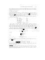
1
User interface design with matrix algebra Harold Thimbleby UCLIC, University College London Interaction Centre It is usually very hard, both for designers and users, to reason reliably about user interfaces. This paper shows that ‘push button’ and ‘point and click’ user interfaces are algebraic structures. Users effectively do matrix algebra when they interact, and therefore we can be precise about some important issues of usability. Matrices, in particular, are useful for explicit calculation and for proof of various user interface properties. With matrix algebra, we are able to undertake with ease unusally thorough reviews of real user interfaces: this paper examines a mobile phone, a handheld calculator and a digital multimeter as case studies. All difficulties in applying the approach correspond to awkward or avoidable complexities in the user interfaces being modelled: using matrix algebra in design therefore encourages designers to avoid such user interface complexities. Categories and Subject Descriptors: B.8.2 [Performance and reliability]: Performance Analysis and Design Aids; D.2.2 [Software engineering]: Design Tools and Techniques—User Interfaces; H.1.2 [Models and principles]: User/Machine Systems; H.5.2 [Information interfaces and presentation]: User interfaces (D.2.2, H.1.2, I.3.6)—Theory and methods General Terms: Design, Human Factors, Performance Additional Key Words and Phrases: Matrix algebra, Usability analysis “It is no paradox to say that in our most theoretical moods we may be nearest to our most practical applications.” A. N. Whitehead 1. INTRODUCTION User interface design is difficult, and in particular it is very hard to reason through the meanings of all the things a user can do, in all their many combinations. Typically, real designs are not completely worked out and, as a result, very often user interfaces have quirky features that interact in awkward ways. It might be hard to design an interactive system, but it is even harder to use one that has poor structure. Detailed critiques of user interfaces are rare, and very little knowledge in design generalises beyond specific case studies. This paper addresses these problems by showing how matrix algebra can be applied to user interface design. The Address: UCLIC, University College London, 26 Bedford Way, LONDON, WC1H 0AP, UK. URL: http://www.uclic.ucl.ac.uk Permission to make digital or hard copies of part or all of this work for personal or classroom use is granted without fee provided that copies are not made or distributed for profit or direct commercial advantage and that copies show this notice on the first page or initial screen of a display along with the full citation. Copyrights for components of this work owned by others than ACM must be honored. Abstracting with credit is permitted. To copy otherwise, to republish, to post on servers, to redistribute to lists, or to use any component of this work in other works, requires prior specific permission and/or a fee. Permissions may be requested from Publications Dept, ACM Inc., 1515 Broadway, New York, NY 10036 USA, fax +1 (212) 869-0481, or [email protected]. 2 · H. Thimbleby paper explains the theory in detail and shows it applied to three real case studies. Push button devices are ubiquitous: mobile phones, many walk-up-and-use devices (such as ticket machines and chocolate vending machines), photocopiers, cameras, and so on are all examples. Many safety critical systems rely on push button user interfaces, and they can be found in aircraft flight decks, medical care units, and nuclear power stations. Large parts of desktop graphical interfaces are effectively push button devices: menus, buttons and dialog boxes all behave as simple push button devices, though buttons are pressed via a mouse rather than directly by a finger. Touch screens turn displays into literal push button devices, and are used, for example, in many public walk-up-and-use systems. The world wide web is the largest example by far of any push button interface. For concreteness, this paper will consider handheld push button devices, and moreover ones that can be represented as finite state machines. Finite state machines are mathematical structures and as such do not exist in any concrete form for users: they are therefore at best a design or analysis tool. Finite state machines have had a long history in user interface design, starting with Newman [10] and Parnas [11] in the 1960s, and reaching a height of interest in user interface management systems (UIMS) work [18]; now the concerns of HCI have moved on [9] — a continual, technology-driven pressure, but one that tends to leave open unfinished theoretical business. Users cannot be expected to reason about the behaviour of finite state machines: they are (typically) far too big, and as a formalism they are so versatile that they have no structure that really helps thinking about them. Obviously some finite state machines will have interesting structure (e.g., ones designed using statecharts [6]), but in these cases it is easier to think about the structure than the finite state machine itself. What the user can see, however, is buttons and their effects. This paper shows that each button is a matrix; it thus turns out that users — whether they know it or not — are doing matrix algebra when they press buttons. Matrices have three very important properties. Matrices are standard mathematical objects, with a history going back to the nineteenth century:1 this paper is not presenting and developing yet another notation and approach, but it shows how an established and well-defined technique can be applied fruitfully to serious user interface design issues. Secondly, matrices are very easy to calculate with, so designers can work out user interface issues very easily, and practical design tools can be built. Finally, matrix algebra has lots of structure and properties: designers and HCI specialists can use matrix algebra to reason about what is possible and not possible, and so on, in very general ways. Matrices are not a panacea for specifying all manner of user interfaces; on the contrary, a major advantage is that difficulties in employing a matrix approach correspond well with difficulties in user interfaces. If designers used matrix algebra, they would be very likely to avoid such user interface complexities in the first place. This paper will give many examples of this claim. It is important to note that many of these poor aspects of user interface design are extremely hard to describe in everyday words, let alone to describe clearly in words: typical user interface design 1 The Chinese solved equations using matrices as far back as 200bc, but the recognition of matrices as abstract mathematical structures came much later. User interface design with matrix algebra · 3 methods (and user interface evaluation methods) would be unable to identify and correct them. 2. FROM FINITE STATE MACHINES TO MATRIX ALGEBRA Finite state machines are often drawn as transition diagrams. A transition diagram consists of circles and arrows connecting the circles; the circles represent states, and the arrows represent transitions between states. Typically both the circles and the arrows are labelled with names. A finite state machine is in one state at a time, represented by being ‘in’ one circle. When an action occurs the corresponding arrow from that state is followed, taking the machine to its next state. A FSM labels transitions from a finite set. Labels might be button names, On , Off , Rewind , say, corresponding to button names in the user interface. In our matrix representation, each transition label denotes a matrix, B1 , B2 , B3 . . . , or in general Bi . Buttons and matrices are not the same thing: one is a physical feature of a device, or possibly the user’s conception of the effect of the action; the other is a mathematical object. Nevertheless, except where confusion might arise in this paper, it is convenient to use button names for matrices. In particular this saves us inventing mathematical names for symbolic buttons, such as ∨ . Pedantically we could define a function B that gives the matrix a button denotes, so for example B ∨ = D; our convention, then, is simply that we omit B, and avoid introducing arbitrary names such as D. The state of the FSM is represented by a vector, s. When a transition occurs, the FSM goes into a new state. If the transition is Bi , the new state is s times Bi , or sBi . Thus finding the next state amounts to doing a matrix multiplication. If we consider states to be labelled 1 to N , then a convenient representation of s is a vector of 0s of length N , with a 1 at position corresponding to the state number; under this representation, the matrices B will be N × N matrices of 0s and 1s (and with certain further interesting properties we do not need to explore here). Instead of having to draw diagrams to reason about FSMs, we now do matrix algebra. However big a FSM is, the formulas representing it are the same size: “sB1 B2 ” could equally represent the state after two transitions on a small 4 state FSM or on a large 1000 state FSM. The size of the FSM and its details are completely hidden by the algebra. Moreover, since any matrix multiplication such as B1 B2 gives us another matrix, a single matrix, say M = B1 B2 , can represent many user actions: “sM ” might represent the state after two button presses, or more. There is a significant theory behind matrices. Matrix multiplication is associative, so the matrix M above has a meaning to the user. If pi , p = 1, is the probability that action Bi is undertaken by a user, then S= pi Bi i is a simple stochastic probability matrix, which can be analysed to obtain statistical information about the user or about the design of the user interface. Such statistical models were explored in detail in an earlier paper [14]. 4 · H. Thimbleby For further information, see [5] for a textbook introduction with applications of FSMs in HCI. There are many textbooks available on matrix algebra (linear algebra); Broyden’s Basic Matrices [4] is one that emphasises partitions, a technique that is used extensively later in this paper. The rest of this paper interleaves reviewing the necessary theory with progressing through worked examples. FSMs are not necessarily device-based: there is no intrinsic ‘system’ or ‘cognitive’ bias. Matrix operations model actions that occur when user and system synchronise. Thus a button matrix represents as much the system responding to a button push as the user pressing the button. Matrices can can represent a system doing electronics to make things happen, or they represent the user thinking about how things happen. The algebra does not ‘look’ towards the system nor towards the user. As used in this paper, it simply says what is possible given the definitions; it says how humans and devices interact . . . 2.1 Introductory examples Matrix multiplication does not commute: if A and B are two matrices, the two products AB and BA are generally different. This means that pressing button A then B is generally different from pressing B then A. This is not yet a deep insight, but it is a short step from this sort of reasoning to understanding undo and error recovery, as we shall see below. In a direct manipulation interface, a user might click on this or click on that in either order. It is important that the end result is the same in either case. Or in a pushbutton user interface there might be an array of buttons, which the user should be able to press in any order that they choose. Both cases are examples of systems where we do want the corresponding matrices to commute. We should therefore either check Click1 Click2 = Click2 Click1 by direct calculation with matrices, or we should design the interface to ensure the matrices have the right form to commute. Just as allowing a user to do operations in any order makes the interface easier to use [16], the analysis of user interface design in this case becomes much easier since commutativity permits mathematical simplifications. You might think that pressing the button OFF is a shortcut for the two presses STOP OFF , for instance as might be relevant to the operation of a DVD player. Let S and O be the corresponding matrices; in principle we could ask the DVD manufacturer for them. The simple calculation SO = O will check the claim, and it checks it under all possible circumstances — the matrices O and S contain all the information for all possible states. This simple equation puts some constraints on what S and O may be. For instance, assuming S is non-trivial, we conclude that O is not invertible. We prove this by contradiction. Assume SO = O, and assume O is invertible. If so, there is a matrix O−1 which is the inverse of O. Follow both sides by this inverse: SOO−1 = OO−1 which can be simplified to SI = I, as OO−1 = I. Since SI = S we conclude that S = I. Hence S is the identity matrix, and STOP does nothing. This is a contradiction, and we conclude that if O is a short cut then it cannot be invertible. If it is not invertible, then in general a user will not be able to undo the effect of OFF . What not being invertible means, more precisely, is that the user cannot return to a previous state only knowing what they have just done. They also need to know what state the device was in before the operation and be able to solve the problem of pressing the User interface design with matrix algebra · 5 right buttons to reach that state.2 3. EXAMPLE 1: THE NOKIA 5110 MOBILE PHONE The menu system of the Nokia 5510 mobile phone can be represented as a FSM of 188 states, with buttons ∧ , ∨ , C , and NAVI (the Nokia context sensitive button: the meaning is changed according to the small screen display). In this paper we have used the definition of the Nokia 5110 as published in [15]. First, we describe the user interface informally in English. The menu structure is entered by pressing NAVI and then using ∧ and ∨ to move up and down the menu. Items in the menu can be selected by pressing NAVI , and this will either access a phone function or select a submenu. The submenu, in turn, can be navigated up and down using ∧ and ∨ , and items within it selected by NAVI . The C key is used for correction, and ‘goes up a level’ to whatever menu item was selected before the last NAVI press. If the last press of NAVI selected a phone function, then C cannot correct it — once a function is selected, the phone does the function and then reverts to the last menu position. The phone starts in a standby state, and in this state C does nothing. We may hope or expect the Nokia’s user interface to have certain properties. It may have been designed with certain properties in mind. Perhaps Nokia used a system development process that ensured the phone had the intended properties. Be all this as it may, we will now show that from a matrix definition of the Nokia we can reliably deduce and check properties. We represent the buttons and button presses by boxed icons like ∧ and C , and we would normally represent the matrices they represent by mathematical names like U and C, which for the present model of the Nokia are in fact 188 × 188 matrices. But the buttons and matrices correspond, and they are essentially the same thing: we may as well call the mathematical objects by names which are the button symbols themselves. So although our sums look like sequences of button presses, they are representing matrix algebra. We can establish, amongst others, the following laws: ∧ ∨ = I ∨ ∧ = I ∧ C = C ∨ C = C i j C = C for 0 ≤ i ≤ 3, i = j but C i = C 4 for 4 ≤ i Here, as usual I is the identity matrix. These are not just ‘plausible’ laws the user interface happens to obey or might often obey, or we would like it to obey: we calculated these identities: they are universally true, facts that can be established directly using the 188 × 188 matrices from the Nokia specification we started from 2 Or the user needs to know an algorithm to find an undo: for instance, to be able to recognise the previous state, and be able to enumerate every state, would be sufficient — but hardly reasonable except on trivial devices. 6 · H. Thimbleby (in fact, we wrote a program to look for interesting identities — we had no real preconceptions on what to find). Some of these identities are not surprising: doing up then down (or down then up — one does not imply the other) has no effect; although it might be surprising that it never has any effect, which is what the identity means. Up or down followed by C is the same as if C had been pressed directly; on the other hand, NAVI C is not the same as C , since when NAVI activates a phone function the C key cannot correct it. 4 5 Finally, direct calculation shows that C = C , and moreover that this is the least power where they are equal. If they are equal, they will be equal if we do the 4 5 5 6 same things to both sides, so C C = C C and hence C = C . By induction, i i+1 C = C for all 4 ≤ i, and hence i C = C 4 for 4 ≤ i The identity means that if C is pressed often enough, namely at least 4 times, further presses will have no effect. In fact, Nokia recognise this: if the C key is held 4 down continuously for a couple of seconds, it behaves like C . 3.1 Inverses Matrices only have inverses if their determinants are non-zero. A property of determinants is that the determinant of a product is the product of the determinants: for any matrices A and B: det(AB) = det(A) det(B) In a product, if any factor is zero, the entire product is zero — zero times anything is zero. So if any determinant is zero, the determinant of the entire product will be zero. What this means for the user is that when they do a sequence of button presses corresponding to the matrix product B1 B2 . . . Bn , if any of them are not invertible (not undoable), the entire sequence will not be invertible. So buttons with matrices that have zero determinants (i.e., are singular) are dangerous: if they are used in error, there is no uniform way to recover from the mistake. The user might have fortuitously kept a record of or memorised their actions up to the point where they made the mistake, and then they might be able to recover using the device’s buttons, but if so they are also having to use this additional knowledge, something external the device cannot help with. If a matrix cannot be inverted (because it is singular) the user cannot undo the effect of the corresponding button, but even if a matrix can be inverted in principle, in practice the user may not be able to undo its effect: they may not have access to all buttons that are factors of the inverse. The user is only provided with particular buttons and hence particular matrices. A routine calculation can establish what the user can do with their actual buttons; a designer may wish to check that every button’s inverse is a product of at least one other button. For example, the determinants of ∨ and ∧ on the Nokia mobile phone are both −1, which is non-zero, and these matrices can be inverted. The user might have broken the ∨ button. In this case, as ∧ is still invertible as a matrix, but the user cannot User interface design with matrix algebra · 7 undo its effect (at least, without knowing a lot about the Nokia and the way ∧ works in each menu level). In contrast to ∨ and ∧ , the matrices C and NAVI are both singular, which means they cannot be inverted. In other words, there is no matrix M such that C M = I or NAVI M = I. Since there is no matrix, there is not even a sequence of button presses that achieves this. But if there is no matrix, there is no such product — whatever the buttons. In user interface terms, this means that if C or NAVI are pressed by mistake, the user cannot in general recover from the error — at least without knowing exactly what they were doing. If a matrix is not invertible, it means the device no longer knows what it was doing, and therefore it cannot go back. 4. PROJECTING LARGE STATE SPACES ONTO SMALLER SPACES Although it is possible to use matrices to model entire systems, often it is undesirable to do so. We may want to reason closely about a few buttons, and ignore the rest of the system. In fact we did this with the Nokia example in the last section: the Nokia mobile phone had a model of 188 states, and while this completely described the menu subsystem of the Nokia phone it did not cover any other features, such as dialling or SMS (short message service, for sending text messages). This was a pragmatic decision, and one that can be justified because other buttons on the phone (such as the digit keys) are ‘obviously’ irrelevant to how the menu system works. But are they really? We need a systematic and reliable approach to getting at the states of systems we are interested in. This section shows how matrices can be used to reliably abstract out just the features that are needed. To project a large state vector to a smaller space, multiply by an appropriate projection matrix. Simply, if the large state space has M states, the projection matrix P has M rows and N columns, then the projected state space vector sP will have N columns (or equivalently, N states). We then consider button matrices operating on sP rather than on s: these matrices will be square N × N matrices, possibly much smaller than the original M × M size. Suppose the fully explicit button matrices are B and the projected matrices are B . All we require is sBP = sP B (i.e., that BP = P B ) to associate with any button matrix (or button matrix product) B the smaller projected matrix B . For concreteness consider a digital clock, and we will be interested in the behaviour of the tens of hours setting button, TENS , and the on/off arrangements. Such clocks must display 24 hours and 60 minutes; they therefore need 24 × 60 = 1440 states just to display the time. We also need an extra state for off, when the clock is in a state displaying no time at all. The state occupancy vector s is therefore a vector with 1441 elements, which is too big to write down explicitly. Our clock has four buttons to increment the corresponding digits, so that a user can set the time. These buttons could be represented fully as 1441 × 1441 matrices. We define a matrix P that projects the state space onto a smaller space, the space we are interested in exploring in detail. Suppose we want to work in the tens of hours space, in which case P will project 1441 states to 4 states: off, or displaying 0, 1, or 2 in the tens of hours column. Thus P will be a matrix with 4 columns and 1441 rows. · 8 H. Thimbleby There is not space here to show P explicitly because it has 5764 elements, and in any case that number of elements would be hard to interpret. The definition of P depends on how states are arranged. We have to choose some convention for the projected state space and for the sake of argument take sP = ([off?] [displaying 0?] [displaying 1?] [displaying 2?]), where [e] means 0 or 1 depending on whether e is true — a convenient notation due to Knuth [7]. If we assume the state vector s is arranged in the obvious way that state 1 is off, state 2 is displaying time 0000, state 3 is time 0001, state 4 is time 0002 . . . state 60 is time 0059, state 61 is time 0100 . . . state 1441 is time 2359, then P will look like this: 1 0 .. . 0 0 P = . .. 0 0 . .. 0 1 .. . 0 0 .. . 1 0 .. . 0 1 .. . 0 0 .. . 1 0 .. . 0 0 0 0 0 .. . 0 0 .. . 0 1 .. . 1 one 600 600 240 row, for off rows the same, for displaying 0 rows the same, for displaying 1 rows the same, for displaying 2 A possible definition of the tens of hours button matrix3 is this: 1 0 TENS = 0 0 0 0 0 1 0 1 0 0 0 0 1 0 The TENS button leaves the clock off it is already off, and otherwise increments the digit displayed by the tens of hours digit. We can confirm this by explicitly working out what TENS does in each of the four states: (1 0 0 0) TENS = (1 0 0 0) (0 1 0 0) TENS = (0 0 1 0) (0 0 1 0) TENS = (0 0 0 1) (0 0 0 1) TENS = (0 1 0 0) If we are only interested in the on/off switch, we do not even care what digit is displayed, and we can project the clock’s 1441 states on to just two, on and off. A new projection matrix Q with 1441 rows and 2 columns is required, but it is 3 To avoid typographical clutter we write TENS rather than TENS . User interface design with matrix algebra · 9 clearer and easier to define Q in terms of P , rather than write it explicitly — here we see another advantage of projecting a huge state space onto something more manageable. 1 0 Q=P 0 0 0 1 1 1 The clock might have an on/off button: ON-OFF = 0 1 1 0 The other buttons on this clock do not change the on/off state of the clock, so in this state space they are identities, e.g., TENS = 1 0 0 1 Or perhaps the clock has two separate buttons, one for on, one for off? ON = 0 1 0 1 , OFF = 1 0 1 0 This looks pretty simple, but we can already use these matrices to make some user interface design decisions. Suppose for technical reasons, when the clock is switched off the digits stay illuminated for a moment (this is a common design problem: due to internal capacitance the internal power supply keeps displays alight for a moment after being switched off). Users might therefore be tempted to switch the clock off again, assuming that their first attempt failed (perhaps because the switches are nasty rubber buttons with poor feedback). It is easy to see from the matrices that a repeated (specifically, double) use of ON-OFF leaves the clock state unchanged, whereas any number of pressings of OFF is equivalent to a single press of OFF . Under these circumstances — which are typical for complex push button devices like DVD players, TVs and so on4 — we should prefer a separate off button that, unlike the ON-OFF button, cannot be used to switch the device on by accident. The scenario does not require an on button; what, then, about switching on? We could arrange for all of the time-setting buttons to switch the clock on, e.g., TENS = 0 1 0 1 We now have a clock with five buttons. This is the same number of buttons as one with a single ON-OFF button, and therefore the same build price. Furthermore, it has the nice feature that if the user attempts to set a digit by pressing a digit 4 The JVC HR-D540EK has the additional complexity that pressing OPERATE slowly (what it calls the button we call ON-OFF in this paper) enters a child lock mode which disables the device. 10 · H. Thimbleby button (say, TENS ) that button always changes what is displayed. Pressing TENS would change nothing to 0, change 0 to 1, change 1 to 2, and change 2 to 0. To define this behaviour requires the previous 4 state model: 1 1 OFF = 1 1 0 0 0 0 0 0 0 0 0 0 , 0 0 0 0 TENS = 0 0 1 0 0 1 0 1 0 0 0 0 , and other buttons . . . 1 0 A similar approach could be used for TVs and DVD players of course. 5. EXAMPLE 2: THE CASIO HL-820LC CALCULATOR Calculators differ in details of their design, and so to be specific we will base our discussion on a particular calculator, the Casio HL-820LC, which is a market-leading and popular handheld (5.5×10cm) calculator. It is a current model and can be readily obtained: the discussion below should be easy to check if required. This section closes with a brief comparison with some differently designed Casio calculators, but our primary concern for this paper is to illustrate the matrix approach; a more general critique of calculators (and a wider range of calculators) can be found elsewhere [13]. The previous section ended by showing how a designer can project a large FSM down to a manageable size. Similarly, users have models of systems that are typically much smaller than the actual implementation model of the systems. We start by drawing a simple arrow diagram representing what happens to the inside state s of the calculator when a button is pressed: press B s −−−−−−→ sB The user has no reasonable way of working out or understanding this because it involves understanding the calculator’s program or its specification, both of which are technical documents of no interest to calculator users; after all, the whole point of the calculator is to do the work! Instead users have some sort of perception of the device and mental model, that somehow transforms something of the internal state s into a mental state. We can call the user’s model of the state m, and the user’s model of the button matrix B . We then obtain this diagram: implementation: s −−−−−−→ sB user model : m −−−−−−→ m B For considering the display and memory of a calculator, the user’s model of the state m need only be two numbers, which we can represent as a vector of two elements: (display memory). The matrices B will then be 2 × 2 matrices, that operate on these vectors. Although a user is very unlikely to think explicitly using User interface design with matrix algebra · 11 matrices, an advantage of 2 × 2 matrices for this paper is we can easily show and reliably calculate what the user can (perhaps not so reliably) work out. As it happens, for the calculator and a display/memory user model the transformation can be represented as a matrix. To show this, for simplicity imagine a calculator that can only handle numbers 0, 1, and 2. The matrix M that represents the user transformation of the system FSM would be something like this: 0 0 0 0 1 M = 1 1 2 2 2 0 0 1 2 0 1 2 0 1 2 This nicely transforms a 10 state implementation into a simple 2 number model that makes more sense to the user. Here we have simply, m = sM . Note that, for illustration purposes, we added a ‘dummy’ state 0 that the user’s model does not distinguish from state 1. Perhaps this is the off state, or an error state, or something else that the user is ignoring for the purposes of understanding the display/memory issues more clearly. In summary, for working through display/memory issues, we can represent the user’s model of the state of the calculator by a row vector (display memory), which we will abbreviate to (d m). We will take d and m to be real numbers, but of course we know that any calculator will implement them using some finite binary representation (or possibly a binary-coded decimal representation). Since we are not going to do serious arithmetic (not even division by zero) in our analysis, the issue of whether d and m are finite or not, what their precision is, how the calculator handles overflow, and so on, will not arise. Each of the calculator’s functions can be represented as a matrix multiplication, as expected. Thus the key AC , which on the Casio HL-820LC clears the display but does not change the memory corresponds to a matrix C where C= 0 0 0 1 . Multiplying the calculator’s state by C changes it to (0 m), as can be seen by working through the calculation: (d m) 0 0 0 1 = (0 m) This is what AC does: it sets d = 0 and leaves m unchanged. Curiously, then, the button called AC does not mean All Clear! Many calculator users press AC repeatedly. We can see that pressing AC twice 12 · H. Thimbleby has no further effect: (d m) In fact, since 0 0 0 1 0 0 0 1 n = 0 0 0 1 0 0 0 1 = (0 m) for all n > 0 it is clear that pressing AC has no effect beyond what can be achieved by pressing it just once (in technical terms, it is idempotent). Users are superstitious — or not certain that the AC button works reliably. The Casio HL-820LC has other buttons. What are their corresponding matrices? Here are some definitions: M+ = M- = add display to memory 1 −1 0 1 AC = MRC = MRC MRC = 1 1 0 1 0 0 0 1 0 0 1 1 0 0 1 0 subtract display from memory clear display recall memory recall and clear memory Other buttons on the calculator are equals, digits, and the usual operators for addition and subtraction, etc. We will not look at them here. However, for completeness we need a ‘do nothing’ or identity operation: 1 0 I = do nothing 0 1 Anything multiplied by I is unchanged. (This standard bit of notation is useful in much the same way that 0 is useful in ordinary arithmetic to represent nothing.) Note that MRC MRC is defined specially by Casio; it does not mean the same as MRC pressed twice, which we can work out: MRC MRC 0 0 0 0 0 0 = 1 1 1 1 1 1 Thus, if MRC has the meaning as we defined in the matrix, then pressing it twice should have no effect: the multiplication shows that apparently MRC MRC = MRC . User interface design with matrix algebra · 13 But on the calculator, MRC MRC is instead defined to clear the memory after putting it in the display. Hence we defined a special matrix for it, but later we shall see how this ambiguity creates problems for the user — which the calculations above warn it may. If MRC MRC does not correspond to the matrix for MRC , aren’t we contradicting ourselves about the user doing matrix algebra? What it means is that our initial understanding of the user’s model of the calculator, namely the state space (d m), was inadequate. The state space should account for whether MRC is or is not the last button pressed. (It is possible to extend the state space to do this, but it becomes much larger.) Casio seem to think MRC MRC is a single operation that the user should think of as practically another button: in this sense we are justified in giving it an independent matrix (it also allows the rest of this paper to use 2 × 2 matrices rather than larger ones). However, the calculator does nothing to encourage the user to think of MRC MRC as a single button: pressing MRC then waiting an arbitrary time then pressing MRC again (as might happen if the user goes for a cup of tea) is treated as the special MRC MRC . In this case, the user would have no sense of MRC MRC being a single ‘virtual’ button. In short, the problems we are glossing indicate a design problem with the HL820LC: if we were designing a new calculator and had the ability to influence the design, we would have made different decisions. What does MRC MRC MRC mean? Since Casio define MRC MRC to mean something special, then MRC MRC MRC could mean either ( MRC MRC ) MRC or it could mean MRC ( MRC MRC ) — which is the same thing the other way around.5 It would not matter if both of these alternatives had the same meaning. But as MRC MRC MRC MRC MRC MRC 0 0 0 0 0 0 0 0 = 1 0 1 1 1 1 1 0 we have established that the three successive key presses MRC MRC MRC is ambiguous: it could mean either ( MRC MRC ) MRC or MRC ( MRC MRC ) — and it matters which! When we look at the calculator to find out how Casio have dealt with this ambiguity, we find that we did not fully understand what MRC does. In fact, as one can establish with some experimenting that MRC only recalls the memory to the display if the memory is not zero; if the memory is zero, MRC does nothing, and MRC MRC sets the memory to zero. What MRC MRC MRC means, then, is “recall memory to display and zero the memory”: on the Casio it means exactly the same as MRC MRC . 5 Provided we consider MRC MRC as a ‘logical’ button, this is an issue of commutativity. Instead, we could consider the matrix M for MRC directly, where our calculation shows M (M M ) = (M M )M , and this would be a failure of associativity. But matrix multiplication is associative! The problem this indicates is that M is bigger than a 2 × 2 matrix, and our calculations projected onto a 2 × 2 matrix are incorrect if we want to capture these idiosyncracies. Had we been designing a new calculator, rather than reverse engineering an existing one, the formal difficulty of representing MRC MRC as defined for this calculator might have encouraged finding a simpler design. Certainly it highlights a design issue that needs further exploration, whether empirical or analytic. 14 · H. Thimbleby 0 0 m = 0, 1 1 MRC = 1 0 m = 0, 0 1 We now have a standard problem. The real calculator behaviour suggests we should extend our user model to handle what it actually does: the MRC button is not a simple 2 × 2 matrix! Or if we were Casio, we could redesign the calculator so that it has a simpler algebra — this is a route I’d prefer, but of course we cannot now change the HL-820LC. What we will do here in this paper is be careful that we never rely on doing MRC when the memory is zero. Since that is the simplest course for us, it is probably also the simplest course for a user. The exception in the button almost certainly makes the calculator harder to use. If the user is doing some sums and repeatedly using M+ and M- they also and additionally have to keep track of whether the memory ever becomes equal to zero: if it does, pressing MRC will behave unexpectedly. If the memory is m, the user expects MRC to leave the calculator in the state (m m), including (0 0) if m = 0, but as Casio designed the calculator it will leave it in state (d 0) in this case! Put another way, modes are messy (as we knew), and the matrix approach makes this very obvious. In general, we have a useful design insight: if we can’t capture a device’s semantics easily, then possibly the device’s design is at fault. Difficult semantics must mean, in some sense, that a device is harder to use than one with simpler semantics. We can find some nice properties; we will look at just two. First, MRC followed by M- sets the display to the memory and clears the memory. It is the same as Casio’s interpretation of MRC MRC : MRC MRC M- MRC 0 0 1 −1 0 0 = 1 1 0 1 1 0 This seems so simple, was the idiosyncratic interpretation of MRC MRC necessary? Secondly, M+ and M- are inverses of each other: M+ M- = 1 1 0 1 1 −1 0 1 = 1 0 0 1 =I Matrix algebra tells us immediately that pressing the buttons in the other order will have the same effect. We can also show this by explicit calculation: M- M+ = 1 −1 0 1 1 1 0 1 = 1 0 0 1 =I So M+ is the inverse of M- and M- is the inverse of M+ . If you press M+ by mistake, you can recover by pressing M- and vice versa. By calculating determinants, it is easy to see that for the Casio calculator, none of the buttons apart from M+ and M- can be inverted. As we showed in Section 3, User interface design with matrix algebra · 15 above, this means that a user cannot undo mistakes with any of the other buttons we have defined (of course a user would end up using digit keys and other features we have not mentioned here).6 5.1 Solving user problems We have defined simple matrices for the memory buttons and the clear button. The Casio calculator can obviously add to memory (using M+ ) and subtract from memory (using M- ). The question, now, is what else would we reasonably want a calculator like this with memory functions to do? If the calculator’s state is the vector (d m) then plausibly we want operations to get to any of these states: Zero display Zero everything Zero memory Show memory Store display Swap memory & display (0 m) (0 0) (d 0) (m m) (d d ) (m d ) Most of these operations are easy to justify in terms of plausible user requirements. The final one, ‘swap,’ which seems more unusual, might be useful for a user who was not sure what was in the memory. One swap will confirm what is in the memory, and used again will put it back and restore the display as it was. We can do some of the operations listed above very easily: for instance, AC achieves zero display (without changing the memory), as we noted earlier. Showing the memory is also done directly, but by MRC : (d m) MRC = (m m) because MRC = and (d m) 0 0 1 1 0 0 1 1 = (m m) To zero everything is fairly easy, since (with the special meaning of two consecutive MRC presses): MRC MRC AC = 0 0 1 0 0 0 0 1 = 0 0 0 0 which will take (d m) to (0 0). However, doing these operations in the other order is not the same at all: 6A careful reader will notice that the buttons we have defined do not allow the user to change the calculator’s state from (0 0), so there is no problem if buttons have no inverse, because the calculator can’t be got into other states anyway! In other words, our 2 × 2 model is too small to make all the points we’d like to from it. 16 · H. Thimbleby AC MRC MRC = 0 0 0 1 0 0 1 0 = 0 0 1 0 = MRC MRC The operations do not commute; the user has to remember the right way round of using them. Indeed, doing MRC AC MRC is different again (as can be confirmed by calculating the product)! The remaining three operations, storing the display, zeroing the memory and swapping, are a lot more tricky than these first few examples. Imagine the user has the calculator displaying some number d and they want to get it into the memory. They must effectively solve this equation: (d m) M = (d d ) It is not difficult to solve this equation in matrix algebra: (d m) M11 M12 M21 M22 = (dM11 + mM21 dM12 + mM22 ) = (d d ) so M11 = 1, M21 = 0 and so on. Putting it all together we get 1 1 M= 0 0 This is not one of the matrices we have got directly available. No button press corresponds to M . Of course users (apart from us!) don’t solve matrix equations explicitly, instead they will have to do some rough work and hard thinking. In the examples here, the complexity suggests it is very likely that no users (except mathematicians) would be able to work out how to do things — the Casio appears to be far too complex if we think the tasks listed above are reasonable for it to support. Fortunately, we have the huge benefit of having a handy design notation which makes things much easier to work out. Once we have worked out a solution, we might say how to use it to solve the problem in the user’s manual: a user does not need to go over all the work again. Alternatively the calculator could be redesigned so that it had a button that did M directly: there would then be little need to explain it in detail in the user manual (or on the back of the calculator). In this case, of course, we’d need to be satisfied that the feature was sufficiently useful that it was worth dedicating a button to. Another possibility (which we’ll see again below) is that it might be possible to choose other functions on the calculator to make working out M a lot easier. Given that the Casio calculator design is fixed, we shall have to work M out as a product from some or all of the matrices we already have. (If Casio had provided a key with a corresponding matrix M things would have been trivial.) It cannot be done with the keys we have defined so far. We need to use, for example, the - and = keys too. We can work out (which as we have seen with MRC and other keys, needs carefully checking by experiment as well) that - MRC = = 1 0 −1 1 · User interface design with matrix algebra 17 with this insight,7 we can establish with more hard thinking (done by Mathematica [19]) that - MRC = M+ MRC = 1 0 −1 1 1 1 0 1 0 0 1 1 = 1 1 0 0 as required.8 If it’s so difficult — both to work out and to do — why would we want to do it? Simple: the calculator has a memory and we might want to store a number we have worked out, currently in the display, into the memory. Surely that is what the memory is for? It seems clear that the calculator should have provided a STORE key to do this operation directly. It would then be very easy to store the display in memory. Note that with the Casio design as it is, this sequence of operations includes matrices that are not invertible: if the user makes a mistake, there is no way to recover (unless the user knows what the state previous was and how to reconstruct it). One needs to use a piece of paper to keep a record of the sums — and if you’re using a piece of paper, what real use is the memory? Next, to get (m d ), which is just swapping over the display and memory, we need to find factors of M in terms of our existing matrices, where M= 0 1 1 0 We might want a swap operation so we could work on two sums at once, one in the display and one ‘backed up’ in the memory. (We could be keeping track of two tallies.) Another use of a swap is to allow the user to perform any calculation on the memory without losing the displayed number: for example, with a swap the user could square root the memory using the standard square root button, and no special memory-root button would be required. Now this M is invertible — a swap followed by a swap would leave the calculator’s display and memory unchanged — so it cannot be a product of any of the existing matrices except M+ or M- , which are the only invertible matrices. Since M+ and M- commute, for any sequence of using them (with no other buttons used between them), their order does not matter. So, to find out what a sequence means, we can collect them together, say putting all the M- first. The most general sequence is then m times n times n m 1 1 1 −1 1 M- M- · · · M- M+ M+ · · · M+ = = 0 1 0 1 0 n −n n−m 1 n Note that M+ = Ma fact that we will use later. Hence M+ can never be M , for any n; we have proved that the swap operation is impossible on the Casio. 7 Fortuituously this particular sequence of keystrokes only requires a 2 × 2 matrix! This simple matrix definition will fail if there is numerical overflow — because the calculator gets ‘stuck’ when there is an error, and our current two-element state space cannot model this feature. 8 There are many other solutions, but this is one of the easier ones. · 18 H. Thimbleby Incidentally, as a by-product of this line of thought, we now have a formula that enables us to find out how to do anything on the calculator that requires a matrix 1 k 0 1 for any integer k Obviously Casio could provide a special SWAP key which does what we want in one press, but it is creative to ask what else could be done. First we prove a swap would have to be achieved in combination with using M- or M+ , assuming no other buttons than those we have so far defined are available. If the new button has matrix S and it helps the user achieve a swap, then it must be the case that there are matrices A and B such that ASB = 0 1 1 0 This is not singular (its determinant is −1), and therefore the determinants of A, S, and B are all non-zero. To solve the equation for S, we get: −1 S=A 0 1 1 0 B −1 A special case is that A and B are both identities, and then S is, of course, the swap matrix itself. If A and B are not singular, then they cannot be products of singular matrices: in short, on the Casio, they can only be composed out of M- and M+ . For example if we wanted a new button S that did a swap when used between M+ and M- , we would solve this equation 1 1 0 1 S 1 −1 0 1 = 0 1 1 0 so S= −1 0 1 1 In words, here S has an English meaning, “Subtract display from memory and display it.” Perhaps we could try A = I and B = M- , to find the operation that when followed by M- gives a meaning equivalent to SWAP . We then need to solve S 1 −1 0 1 = 0 1 1 0 which gives S the English meaning, “Add the display to the memory, and display the original memory.” A more general approach is possible. Earlier we gave the general form for any n number of M- or M+ used together, namely M+ for positive or negative n. We can m n solve the equation for M+ S M+ = SWAP and get User interface design with matrix algebra S= −m 1 1 + mn n · 19 In other words, there are no forms that would give a brief and concise natural interpretation for a new button S . Moreover, any meaning we might have liked for S can be achieved using some combination of SWAP , M- and M+ : if we have SWAP we do not need any of these esoteric buttons. Overall, then, it would be better to have a SWAP button, or collect persuasive empirical evidence that users do not want a swap operation! Finally, consider the zero memory operation. Here we need to find a matrix M such that (d m) M = (d 0) The Casio has no key that does this directly, so — as before — we will have to find a sequence of button presses B1 B2 · · · Bn whose matrices multiply together to make M . If we had a STORE key, all this could have been achieved by doing STORE MRC MRC : the STORE stores the display in memory, then the double- MRC recovers memory and sets it to zero. We can check our reasoning: STORE MRC MRC 1 1 0 0 1 0 = 0 0 1 0 0 0 and (d m) 1 0 0 0 = (d 0) Although the Casio does not have a STORE button, we have already worked out a sequence that is equivalent to it, namely - MRC = M+ MRC . So to put zero in the memory, we should follow it by MRC MRC , which would mean this: - MRC = M+ MRC MRC MRC but this has got that problematic sequence of three consecutive MRC presses we examined earlier. We discovered that the Casio would treat this as meaning the same as - MRC = M+ MRC MRC Coincidentally this gives the required matrix, exactly what we wanted. There is no shorter solution. Earlier we said that the potential ambiguity of MRC MRC MRC could cause problems. Yet here it looks like Casio’s design helps. Actually, we did not know Casio’s design decision would help — we had to work it out by doing the relevant matrix multiplications. In other words, to find out how to perform a trivial and plausiblesounding task, we had to engage in formal reasoning that is beyond most users. This strongly suggests the calculator is badly designed in this respect. 20 · H. Thimbleby Add display to memory Subtract display from memory Show memory Zero display Zero memory Zero everything Store display Swap memory & display Table 1. M+ MMRC AC - MRC = M+ MRC MRC MRC MRC AC - MRC = M+ MRC impossible How the Casio HL-820LC does memory operations (with shortest solutions shown). 5.2 Summary and comparisons with other designs Table 1 summarises our results for the Casio HL-820LC. There is no inevitablility about these results: Casio themselves make other calculators that embody different design decisions. The Casio HS-8V has a change sign button: +- = / −1 0 0 1 change sign Since this button is invertible, it provides more ways of attempting to factor the swap operation. Indeed, M+ - MRC = M+ +/- = 0 1 1 0 which is a swap. This harder to do — or at least, longer — than storing the display in the memory (on either the HL-820LC or this, the HS-8V), and the same usability comments apply. The Casio MS-70L does not have an MRC button, instead having an MR button. The matrix for this is the same as a single press of the HL-820LC’s MRC : MR = 0 0 1 1 Further, MR MR = MR : no special meaning is attached to repeated use of this button (which is what we expect from its matrix definition above). As noted earlier in this section, the HL-820LC’s idiosyncratic meaning for MRC MRC can be achieved on the MS-70L by MR M- . In other words, there does not seem to be an intrinsic reason why the HL-820LC was designed so confusingly. The Casio MS-8V has the MS-70L buttons together with a MC as a single key, and it has a button MU which has nothing to do with memory but is a kind of percent key, mark up. The different Casio designs, MS-70L and MS-8V, both have much simpler semantics than the HL-820LC or HS-8V, and one might therefore imagine they are much easier to use reliably. However, they both share with the HL-820LC the absence of the STORE button. User interface design with matrix algebra · 21 6. EXAMPLE 3: THE FLUKE 185 DIGITAL MULTIMETER Our final example is a digital multimeter, an electrical measuring instrument. The Fluke 185 has ten buttons, four of which are soft buttons with context-sensitive meanings, and a rotary knob with seven positions. It has a 6.5×5cm LCD screen with about 50 icons, as well as two numeric displays and a bar graph. It has the most complex user interface of the examples considered in this paper. Furthermore, it is a safety critical device: user errors with it can directly result in death. For example, if the Fluke 185 meter is connected to the AC mains electricity supply but set to read DC volts, it will not warn that the voltage is potentially fatal. As a general purpose meter, it can be connected to sensors, such as the Fluke carbon monoxide sensor, and a misreading could lead to gas poisoning — if the meter is set to AC volts it would read 0 whatever the DC voltage from the sensor. When measuring amps the meter, cables and the device being tested could overheat and cause a fire (or even an explosion). And so on; user/design error can lead to immediate and possibly catastrophic physical consequences. A multimeter should only be used by competent users, and therefore the trade-offs between usability and interface complexity are different than general use products (such as mobile phones). However, unlike a professional interface (such as an aircraft cockpit), multimeters may be used by users competent in the domain but who do not fully understand or have forgotten details of the user interface. Thus the user interface should not have many modes, feature interactions, timeouts or other features that are not essential in the domain; where possible it should utilise warnings, utilise interlocks, and be self-explanatory, etc. Such issues are very important and require careful consideration, based on a deep understanding of the domain (both technical and regulatory) and of human error and so on. These issues go beyond matrix algebra and this paper is silent on them, beyond noting the general point that there is a danger that technical concerns take precedence over user interface concerns, and that user interface quality will suffer. As a case in point, the Fluke 185 conforms to seven types of safety standard and a quality standard (ISO9001), but to no user interface standard. 6.1 Partitioned matrices Matrices are normally considered as arrays of numbers or scalars; in fact any values can be used, provided they can be ‘added’ and ‘multiplied.’ Matrices themselves have these properties, and therefore matrices can be built up, or partitioned, out of submatrices. Consider a matrix M partitioned into four submatrices: M= ... M11 .... M12 ........................... ... M21 .... M22 The submatrices (M11 etc) need not all be the same size, though they must conform (be the right size) for the operations required of them. Thus if this partitioning of M is used to multiply a state vector s, partitioned as (s1 ... s2 ), then the number of columns of s1 must equal the number of rows of M11 etc. If s and M conform in this way, the partitions can be multiplied out: 22 · H. Thimbleby . M .... M ... .. 11 .. 12 ........................... ... = s1 M11 + s2 M21 ..... s1 M12 + s2 M22 s1 .... s2 M21 .... M22 Mathematically this is necessarily correct, regardless of the structure of the FSM and buttons we are describing. We can see, for example, that if M21 is zero, the complete behaviour of the s1 component of the system can be understood even completely ignoring the s2 component: . M .... M ... .. 11 .. 12 ........................... ... = s1 M11 ..... s1 M12 + s2 M22 s1 .... s2 0 .... M22 Whether a user fully understands s1 or not (they may understand a subpartition of it), no knowledge of s2 need interfere with their understanding. Whatever befalls the s2 component, we can abstract the properties of s1 and M11 independently. Similarly we can understand the s2 component of the system completely even ignoring the s1 component provided M12 is zero, and so on. Since it seems desirable to design user interfaces where users can understand parts of the system independently, designing systems with zero submatrices is a powerful design heuristic. For the Fluke 185, we will see that zero submatrices occur naturally and repeatedly. 6.2 Specifying the Fluke 185 Since the Fluke 185 is very complex, we will not attempt a full analysis; our purpose is to indicate how its various features can be handled using matrices. The Fluke’s rotary knob has the nice feature that its meaning depends only on its current position. A rotation to ‘off’ can be modelled by OFF , as if it was an independent button. (If the knob was on a safe, then the security of the safe would depend on sequences of knob positions, and we would need to model knob positions as pairs, such as V → OFF if it is turned to off from the volts position.) The next feature to model is that the meter can be off or on. When it is off, no button does anything, and the knob has to be turned away from the off position to turn it on. Assume the off state is state 1; then the state vector (1 ... 0) represents the meter off, and the state vector (0 ... s) represents it in any state in the subvector s other than off. For generality, represent any button (or knob position) other than OFF by B . Let B represent the effect of any such button when the meter is on (so sB is the effect of button B on state s when it is on), then the matrix that correctly extends to an on/off meter is ... 1 .... 0 ................. ... 0 .... B If the meter is in state (x ... s), this partitioned matrix transforms it to state (x ... sB). Thus if it was off (x = 1, s = 0) it is still off; if it was on (x = 0) it is still on and the on state s has been transformed as expected to sB. Note that no button B embedded in a matrix of this form can switch the meter off. User interface design with matrix algebra · 23 The off switch takes every state to off, and its matrix would have the particularly simple structure as follows (here written explicitly for a FSM with 6 states, including off, which is state 1): Off = ... 1 .... 0 ... 1 .... 0 ... 1 .... 0 ... 1 .... 0 ... 1 .... 0 ... 1 .... 0 0 0 0 0 0 0 0 0 0 0 0 0 0 0 0 0 0 0 0 0 0 0 0 0 This takes any state (x ... s) to (1 ... 0) as required. Repeating off does not achieve anything further; we can check by calculating Off Off = Off , which is indeed the case. Mechanically, because OFF is a knob position, it is impossible to repeat off without some other intermediate operation: thus it is fortunate it is idempotent and the user would not be tempted to ‘really off’ the meter! (Compare this situation with the AC key on the calculator.) In short, the knob’s physical affordance and its meaning correspond nicely [17]. In summary, once we have explored the meaning of off and the general behaviour of other buttons whether the meter is on or off, as above, we can ignore the off state and concentrate our attention on the behaviour of the meter’s buttons when it is on. Partitioning is a powerful abstraction tool, and henceforth we can assume the meter is on. The meter has a display light, which can be switched on or off. The behaviour of the meter is otherwise the same in either case. Introducing a two-state mode (light on, light off) therefore doubles the number of states. If the ‘light off’ states are 1 . . . N , then the ‘light on’ states are (N + 1) . . . 2N , a simple way of organising the state space is that switching the light on changes state from s to s + N , and switching it off changes the state from s to s − N . Now represent the state vector by (off ... on). The light switch can be represented by a partitioned matrix L that swaps the on and off states: ... 0 .... I ............... ... I .... 0 L= The submatrices I and 0 here are of course all N × N matrices. This works as required, as can be seen by multiplying out its effect on a general state vector ... 0 .... I . . ............... ... (x . y) = (y ... x) I .... 0 For any other operation H (such as pressing, say, the HOLD button) we want its effect in the light off states and the light on states to be the same. Again this is achieved using partitioned matrices, but in the following form: 24 · H. Thimbleby ... H .... 0 ................... ... 0 .... H Here, the submatrix H in the top left is applied to the light off states, and the submatrix H in the lower right is applied to the light on states. For example, whatever state the meter is in with the light off, it goes to off H as required; and if the meter’s light is on, then off = 0 and off H = 0. From this matrix, it is clear that H behaves as intended, identically in either set of states, and in particular it does not switch the light on or off. Thus matrices easily model the behaviour of all buttons. This recipe for handling any matrix H is independent of the light switch matrix. Thus we can consider the design of the meter ignoring the light, or we can consider the light alone, or we can do both. As before, this freedom to abstract reliably is very powerful. Indeed, if we were trying to reverse engineer the complete FSM for the meter, building it up from the matrices in this way for each button would be a practical approach. Given the partitioned structure of the meter’s button matrices, it is easy to show that the light switch matrix L commutes with all matrices (except OFF , which requires L to be a submatrix of itself; see also §6.3), which means a user can start a measurement and then switch the light on, or first switch the light on — the results will be the same. Other modes, such as measurement hold, can be treated similarly. At switch on, the meter allows 12 features to be tested, activated or adjusted. For example, switching on while pressing the soft F4 key causes the meter to display its internal battery voltage. (Because this is a switch-on feature, the soft key is not labelled; a user would need to remember this feature.) As so far described, this is easy to model: the meter has one extra state for this feature, and it is reached only by the sequence OFF V F4 , where V F4 represents a simultaneous user action. Its matrix is routinely defined from submatrices. However, as the Fluke meter is defined, the light button does not work in the new state: rather than switching on the light, it exits the new state and puts the meter into normal measuring mode (i.e., the state corresponding to the normal meaning of whatever the knob is set to). If we are to model this feature, the elegant ‘law’ about the light matrix and other button matrices needs complicating: again, an idiosyncratic user interface feature is hard to model in matrix algebra. Although we do not have space to go into details here, this awkwardness with matrix representation seems to be an advantage:9 had Fluke used a matrix algebra approach, they would have been less likely to have implemented this special feature. Indeed, the meter has a menu system (with 8 functions) that can be accessed at any time: why wasn’t the battery voltage feature put in the menu, so its user interface was handled uniformly? The Fluke meter has a shift button, which changes the meaning of other buttons if they are pressed immediately next. (It only changes the meaning of three buttons, including itself, all of which anyway have extra meanings if held down continuously; 9 It requires a 3 × 3 partitioning, and no longer has the nice abstraction property; see §6.5 for other examples. User interface design with matrix algebra · 25 additionally, the shift button has a different, non-shift, meaning at switch on.) In general if S represents a shift button and A any button, we want SA to be the button matrix we choose to represent whatever “shifted A” means, and this should depend only on A. For any button A that is unaffected by the shift, of course we choose SA = A. Since the shift button doubles the number of states, we can define it in the usual way as a partitioned matrix acting on a state vector (unshifted-state ... shifted-state). Since (at least on the Fluke) the shifted mode does not persist (it is not a lockable shift), all buttons now have partitioned matrices in the following simple form ... Aunshifted .... 0 ........................................... ... .... Ashifted 0 and ... 0 .... I ............... ... S= I .... 0 which (correctly) implies pressing SHIFT twice leaves the meter unshifted (since the submatrices are all the same size and SS = I). For a full description of the meter, the various partition schemes have to be combined. For example, we start with a matrix Rbasic to represent the RANGE button (the RANGE button basically operates over 6 or so range-related states, the exact number depending on the measurement), and we build up to a complete matrix R which represents the RANGE button in all contexts. As it happens R shifted is equal to R, and we can define the shift matrix: ... Rbasic .... 0 ... Rs = .................................. 0 .... Rbasic Next we extend Rs to work with the light button. Again, R is the same whether the light is on or off, so we require: ... Rs .... 0 ... Rsl = ..................... 0 .... Rs Now Rsl defines the subset of the RANGE button’s meaning in the context of the additional features activated by the shift key and the light keys. Note that Rsl = Rls (the meaning is independent of the order in which we construct it) as expected — but see qualifications in §6.3. Next we extend Rsl so R works in the context of the meter being on or off: ... 1 .... 0 ... R = ................... 0 .... Rsl This completes the construction of R with respect to the features of the meter we have defined so far. Incidentally, this final matrix illustrates a case where the 26 · H. Thimbleby submatrices are not all square and not all the same size. If Rbasic is a 6 × 6 matrix, this R is 25 × 25. 6.3 Qualifications Sadly we idealised the Fluke 185, and the real meter has some complexities that were glossed in the interests of brevity. The main qualifications are described in this section. We claimed that the construction of the R matrix to represent RANGE was independent of the order of applying shift and light constructions. Although this is true as things are defined in this paper, it is not true for the Fluke 185, a fact which we discovered as soon as we checked the claim! The light and shift buttons do not commute on the Fluke: SHIFT LIGHT = LIGHT SHIFT . This quirk can only make the Fluke harder to use (it also makes the user manual a little less accurate, and it will have made the meter harder to program).10 In fact, the RANGE button has different effects under different measurement conditions, a different effect at power on, and it has a different effect in the menu and memory subsystems, and another effect when it is held down for a few seconds. The range feature also interacts with min/max; for example, it can get into states only in min/max mode where autoranging is disabled. For simplicity, we ignored these details, which would be handled in the same way (but unfortunately not as cleanly) as the example features. Such feature interactions make the matrix partitions not impossible, but too large to present in this paper. The Fluke 185 has many feature interactions. It seems plausible to conclude that Fluke put together various useful features in the meter but did not explore the algebra of the user interface. The user interface, when formalised, therefore reveals many ad hoc interactions between features, all of which tend to make the user interface more complex and harder to use, and few or none of which have any technical justification. The Fluke also has time dependencies. These can all be handled by introducing a new matrix τ which is considered pressed every second, however the result is mathematically messy and not very illuminating. As elsewhere in this paper, we claim that had the designers specified the user interface fully and correctly, they would naturally have wanted to avoid such messiness; furthermore, as we can see no usability benefits of the timeouts, to avoid the mathematical messiness would have improved the user interface design. 6.4 Reordering states Section 6.2 made repeated use of partitioned matrices and made claims about the relevance of the structure of matrices to the user interface. However it is not immediately obvious that as partition structures are combined (e.g., for on/off and other features) that any relevant structures can be preserved. This section briefly considers this issue, and shows that it is trivial. 10 If the meter’s program is modularised, this ‘quirk’ requires wider interfaces or shared global state, both of which are bad programming practice and tricky to get correct. If the meter’s program is not modular, then any ad hoc feature is more-or-less equally easy to program; but this is not good practice: because there is then no specification of the program other than the ad hoc code itself. User interface design with matrix algebra · 27 A user need not be concerned with state numbering, and in general will have no idea what states are or are numbered as. From this perspective we can at any time renumber states to obtain any matrix restructuring we please, provided only that we are methodical and keep track of the renumberings. Whilst this statement is correct, it is rather too informal for confidence. Also, an informal approach to swapping states misses out on an important advantage of using matrices to do the job cleanly. Any state renumbering can be represented as consistent row and column exchanges in a transition matrix. For example, if rows 2 and 3 are swapped, and columns 2 and 3 swapped, then we obtain the equivalent matrix for a FSM but with states 2 and 3 swapped. In general any renumbering is a permutation which can be represented by a matrix P . If M is a matrix, then P M P T is the corresponding matrix with rows and columns swapped according to the permutation P . If several permutations are required, they can either be done separately or combined, whichever is more convenient: e.g., as P1 P2 M P2T P1T or as P3 M P3T . In short, throughout this paper, when any matrix M was presented, implicitly a permutation P was chosen to present it cleanly: we wrote down a neat M to represent P M P T . 6.5 Remaining major features Consider the Fluke 185 autohold feature. Often a user cannot both look at the meter and handle the probes. The Fluke 185 provides two features to help: a HOLD button freezes the display when it is pressed, and the AUTOHOLD feature (holding down the HOLD button for a couple of seconds) puts the meter into a mode where it will automatically hold any stable non-zero measurement. As so far described, modelling this simply requires a 2 × 2 partitioned matrix: the meter has two sets of state, normal ones and autohold ones. The AUTOHOLD simply swaps between the two, in the same way as the light on/off button: ... 0 .... I ............... ... I .... 0 Abasic = Note how pressing the button again gets the meter out of autohold mode, and because both submatices are identities, returns the meter to the original state. In fact, autohold is not available in capacitance measurements.11 There is therefore one state where the autohold leaves the meter in the same state, namely the capacitance state. Introduce a permutation P so that the capacitance state is the first state, as this allows us to write down the autohold matrix in a particularly simple form: 11 The meter may not implement autohold for capacitance possibly because the meter is unable to measure capacitance fast enough, and incomplete readings might be confused by the meter for stable readings. On the other hand, because capacitance measurements can be slow — minutes — users would appreciate the autohold’s automatic beeping when the measurement was ready. 28 · H. Thimbleby Acapacitance ... ... 1 .... 0 .... 0 ... ... ........................ T =P 0 .... 0 .... I ........................ P ... ... . . 0 ... I ... 0 This is essentially the same matrix as before, except state 1 goes to state 1 (courtesy of the top left 1). One identity has lost a row (and column) because it no longer takes capacitance to autohold-capacitance; the other identity has lost a row (and column) because the model no longer has an autohold-capacitance state to be mapped back to capacitance. In fact, there are several states that are affected like this: capacitance has 9 ranges, covering 5nF to 50mF and an automatic range. Now let P permute the 9 capacitance states we are modelling to states 1 to 9. The single 1 of the matrix above that mapped a notional capacitance state to itself now needs to be generalised to an identity that maps each of the nine states to themselves. Of course this is a trivial generalisation as the relevant states are consecutive: ... ... I .... 0 .... 0 ... ... T ........................ =P 0 .... 0 .... I P ........................ ... ... 0 .... I .... 0 Acapacitance-ranges Here the top left identity submatrix is 9 × 9. Since the permutations P — being permutations of arbitrary state numberings — do not typically add a great deal to our knowledge of the system, we may as well omit them, and this is what we did elsewhere in this paper. We can make a usability comment on this aspect of the user interface design of the Fluke 185. The matrix Acapacitance-ranges has more information in it that the matrix Abasic (even allowing for Abasic to range over all nine states). Understanding the meter as designed therefore imposes a higher cognitive load on the user; also the user manual should be slightly larger to explain the exception (in fact, the Fluke manual does not explain this limitation). It is strange that autohold is not available for capacitance (perhaps increasing its time constant if necessary), since on those possibly rare occasions when the user would want it, it would presumably be both extremely useful to have it and extremely surprising to find it is not supported. 6.6 Soft buttons The Fluke multimeter has soft buttons, and we have now reviewed appropriate matrix methods to handle them. The Fluke has four soft buttons, for example pressing F1 behaves variously as VERSION , AC , BLEEP , Ω or ◦ C . In some set of states, F1 means AC and in another set of states it means BLEEP , and so on. Let P be a permutation of states that separates these sets of states. The matrix for F1 can then be written clearly: User interface design with matrix algebra · 29 VERSION ....................... AC ....................... F1 = P BLEEP P T ....................... Ω ....................... ◦ C We may be interested in, say Ω alone, but it is a rectangular matrix. We can define square matrices like ... I .... 0 Ω = Q ............... QT Ω and this definition of Ω effectively means the same as a Ω button that is available at all times, but when pressed in states where (as a soft button) it would not have been visible it does nothing, by its identity submatrix. 7. CONCLUSIONS It might be argued that it seems obvious that users do not engage in matrix algebra when using typical user interfaces. Of course users do not do explicit matrix algebra (after all, most user interfaces are supposed to make tasks easier, not require the user to work out exactly what is going on!); but users do do implicit matrix algebra. They do so in much the same way that putting an apple in a pile of apples “adds one” even if you do not want to do the sums. Users of apple piles will be familiar with all sorts of properties (e.g., putting an apple in, then removing an apple leaves the same quantity; or, you cannot remove more apples from a pile than are in it; and so on) even if they do not do the mathematics explicitly. Likewise, users will be (or could well be) familiar with the results of matrix algebra even if they do not do the sums. Only a philosophical nominalist could disagree [3]. Our use of matrix algebra in this paper reveals persuasively that some apparently trivial user interfaces are very complex. We suggest that the arbitrary complexity we uncovered in some systems is a sign of bad design (it certainly is bad engineering, if not bad user interface design), though more precisely the arbitrary complexity begs usability questions that should be addressed by employing empirical evaluation methods. However, this paper raises a question: If some usability issues are so complex they are only describable with mathematics, how can ordinary usability evaluation methods uncover them? In areas of safety critical systems, this is a very serious question. At least one response is to design systems formally to be simpler, so that there are plausibly no such overwhelmingly complex usability issues to find or fix. Another response is to use formal approaches to support design, such as matrix algebra, so that designers know what they implementing: the results of usability evaluations can then be used to help fix rather than disguise problems. 30 · H. Thimbleby Reasoning about user interfaces at this level of detail (if not avoided) is usually very tedious and error prone. Matrices enable calculations to be made easily and reliably, and indeed also support proofs, of both general and detailed user interface behaviour. In fairness to Casio is should be pointed out that the user interface problems identified arise mainly because the calculator only provides the three memory keys MRC , M+ and M- . Many calculators made by Casio and other manufacturers are similiar in this respect and will therefore have similar usability problems (though perhaps the meanings of their MRC MRC or AC AC repetitions will differ, etc). Very likely, as suggested in the box above, the extreme complexity of doing memory operations are why users, designers and usability professionals have all ignored the poor usability of calculators. They are far too hard to think about! With the digital multimeter, for example, the intricacy and specificity of feature interactions apparently encouraged them to be overlooked; they were probably considered by designers, if at all, as exceptional and unusual behaviour. For the time being it remains an unanswered empirical question whether the apparently unnecessary complexities of the Casio calculator or the Fluke 185 make them superior designs than ones that we might have reached driven by the æsthetics of matrix algebra. However, it is surely an advantage of a formal approach that known (and perhaps rare) interaction problems can be eliminated at the design stage, and doing so will strengthen the validity of any further insights gained from employing empirical methods. Certainly, in comparision with informal evaluations (e.g., [12], which comments on other Fluke instruments), a matrix algebra approach can provide specific insights into potential design improvement, and ones moreover that are readily implemented. There is much scope for usability studies of better user interfaces of well-defined systems, rather than (as often happens) studies of how users cope with complex and poorly defined interfaces. Many centuries of mathematics have refined its tools for effective and reliable human use — matrix algebra is just one example — and this is a massive resource that user interface designers should draw on to the full. Acknowledgements Harold Thimbleby is a Royal Society-Wolfson Research Merit Award Holder, and acknowledges their support. The author is also grateful for very constructive comments from David Bainbridge, Ann Blandford, George Buchanan, Paul Cairns and Matt Jones. REFERENCES [1] M. A. Addison, & H. Thimbleby, “Intelligent Adaptive Assistance and Its Automatic Generation,” Interacting with Computers, 8(1), pp51–68, 1996. [2] J. L. Alty, “The Application of Path Algebras to Interactive Dialogue Design,” Behaviour and Information Technology, 3(2), pp119–132, 1984. [3] J. R. Brown, Philosophy of Mathematics, Routledge, 1999. [4] C. G. Broyden, Basic Matrices, Macmillan, 1975. [5] A. Dix, J. Finlay, G. Abowd, R. Beale, Human-Computer Interaction, 2nd. ed., Prentice Hall, 1998. [6] I. Horrocks, Constructing the User Interface with Statecharts, Addison-Wesley, 1999. User interface design with matrix algebra · 31 [7] D. E. Knuth, “Two Notes on Notation,” American Mathematical Monthly, 99(5), pp403–422, 1992. [8] L. Lamport, “TLA in Pictures,” IEEE Transactions on Software Engineering, 21(9), pp768–775, 1995. [9] B. Myers, “Past, Present, and Future of User Interface Software Tools,” in J. M. Carroll, editor, Human-Computer Interaction in the New Millenium, Addison-Wesley, 2002. [10] W. M. Newman, “A System for Interactive Graphical Programming,” Proceedings 1968 Spring Joint Computer Conference, 47–54, American Federation of Information Processing Societies, 1969. [11] D. L. Parnas, “On the Use of Transition Diagrams in the Design of a User Interface for an Interactive Computer System,” Proceedings 24th. ACM National Conference, pp379–385, 1964. [12] J. Raskin, The Humane Interface, Addison-Wesley, 2000. [13] H. Thimbleby, “Calculators are Needlessly Bad,” International Journal of Human-Computer Studies, 52(6), pp1031–1069, 2000. [14] H. Thimbleby, P. Cairns & M. Jones, “Usability Analysis with Markov Models, ACM Transactions on Computer Human Interaction, 8(2), pp99–132, 2001. [15] H. Thimbleby, “Analysis and Simulation of User Interfaces,” Human Computer Interaction 2000, BCS Conference on Human-Computer Interaction, edited by S. McDonald, Y. Waern and G. Cockton, XIV, pp221–237, 2000. [16] H. Thimbleby, “Permissive User Interfaces,” International Journal of Human-Computer Studies, 54(3), pp333–350, 2001. [17] H. Thimbleby, “Reflections on Symmetry,” Proc. Advanced Visual Interfaces, AVI2002, pp28–33, 2002. [18] A. I. Wasserman, “Extending State Transition Diagrams for the Specification of Human Computer Interaction,” IEEE Transactions on Software Engineering, SE-11(8), pp699–713, 1985. [19] S. Wolfram, The Mathematica Book, 4th. ed., Cambridge University Press, 1999.