1
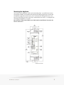
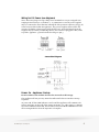
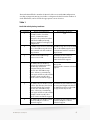
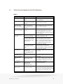
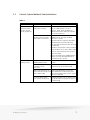
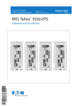
Hardware Installation &
Troubleshooting Guide
Tofino Industrial Security Solution
Version 1.0.0
Copyright Information
©By res Security Inc
While this information is presented in good faith and believ ed to be accurate, By res Security Inc.
disclaims the implied warranties of merchantability and fitness for a particular purpose and makes no
ex press warranties ex cept as may be stated in its written agreement with and for its customers. In no
ev ent is By res Security Inc. liable to any one for any indirect, special or consequential damages. The
information and specifications in this document are subject to change without notice.
Tofino™, Tofino™ Industrial Security Solution and Tofino™ Intrinsically Secure are trademarks of
By res Security Inc. Other brand or product names are trademarks of their respectiv e owners.
While ev ery precaution has been taken in the preparation of this document, the publisher and the
author assume no responsibility for errors or omissions, or for damages resulting from the use of
information contained in this document or from the use of programs and source code that may
accompany it. In no ev ent shall the publisher and the author be liable for any loss of profit or any
other commercial damage caused or alleged to hav e been caused directly or indirectly by this
document.
© 2009 Byres Security Inc.
i
Table of Contents
Part I Introduction
1
Part II Installation Guide
1
Part III Troubleshooting
7
3.1 Tofino Security Appliance (SA) LED Indications
8
3.2 Control System/Network Communications
9
3.3 Tofino CMP to Tofino SA Communications
Part IV Certification
10
11
4.1 Europe
11
4.2 USA
11
4.3 Canada
12
Part V Technical Support
© 2009 Byres Security Inc.
13
ii
1
Introduction
This “inline” Tofino SA Ethernet appliance can be used to protect HMI, DCS,
PLC or RTU control dev ices, as clusters, or as indiv idual dev ices.
The Tofino Industrial Security Sy stem consists of two additional core
components not cov ered by this manual:
· The Central Management Platform (CMP) - a Windows-based management
sy stem and database for centralized monitoring and configuration of each
Tofino SA, regardless of its phy sical location in the company network.
· Loadable Security Modules (LSM) - a v ariety of software plug-ins prov iding
security serv ices such as firewalls, intrusion detection sy stems (IDS) and
v irtual priv ate network (V PN) encry ption. One, or more, LSMs can be
downloaded into a Tofino SA, to prov ide a customized security function to
suit the requirements of the control sy stem.
LSMs require an activ ated software license. For information about LSM
license activ ation, consult the Tofino CMP help or the Tofino CMP User's
Manual.
2
Installation Guide
Unpacking
Unpack the appliance and check it for damage. Do not use any parts that show
ev idence of damage.
Preparation
To install the Tofino SA y ou will need:
1 . A 3mm straight blade screwdriv er
2. 9...32V DC supply with 350mA current (@24V ) per appliance. A second (i.
© 2009 Byres Security Inc.
1
e. redundant) supply is optional. (Note: 22V DC minimum is required for
1 8V power fail detection option.)
3. Wire for DC power & power-fail connections
4. Two 1 0/1 00 base-T cables, preferably screened, to connect the Tofino SA
between the network and the equipment being protected.
5. A suitable 35mm DIN rail location to mount the appliance (optional - see
mounting details).
© 2009 Byres Security Inc.
2
Mounting the Appliance
At the back of the appliance, push out the mounting clips - top and bottom. Press
the appliance firmly onto the DIN rail and push mounting clips back in. Check that
the appliance grips the rail securely . Note: An alternativ e fix ing method is to use
M4 screws through the holes in the clips (1 52mm between centres - see diagram) for
mounting the appliance to a panel.
Record the T ofino ID num ber (see label) & the installation location for
future reference
© 2009 Byres Security Inc.
3
Wiring for DC Power (see diagrams)
Note: These two plugs use cage-clamp screw terminals to accept a stripped wire,
ranging in size from 24 to 1 2 AWG (0.2 – 2.5mm2) One or two DC power supplies
may be connected to the Tofino SA utilizing the four-position connector plug (5–8)
at the bottom of the Tofino SA appliance. Two power supplies will not share the
current; the higher v oltage supply will take the load. Power fail signals from the
supplies may be used by connecting them to the connector plug (pins 1 & 2) at the
top of the appliance - ground returns should go to pin 3.
Connection Diagram
Power On - Appliance Startup
Do not connect the T ofino SA into the network at this stage.
The appliance will not pass any network traffic until it has ex ecuted its startup
sequence.
At power ON, all four LED indicators are lit and the appliance will commence its
startup sequence. At the end of the startup sequence, (i.e. after approx . 1 minute)
the Pow er LED will remain ON, but the Fault, Event and Mode LED indicators will
all be ex tinguished to show the sequence is complete.
© 2009 Byres Security Inc.
4
Network Connection
Note: The appliance must hav e completed its startup before any network
connections are made.
1 . Connect an RJ45 patch cable from the network switch/router to the
“Unsecured” Tofino SA port (
).
2. Connect an RJ45 patch cable from the “Secure” Tofino SA port (
network port of the equipment being protected.
) to the
3. Check that the y ellow “Link activ ity ” light is flashing on both of the network
sockets to show network traffic.
The green “Speed” light will come on if the link is operating at 1 00Mb/s.
IMPORTANT: An unconfigured Tofino SA will pass all network traffic and will not
prov ide any security . Check with y our network administrator to find out if the
Tofino SA is pre-configured, or read the Tofino CMP User's Manual for information
on how to configure the appliance and thus make it secure.
USB Load/Save
Loading New Configuration or Firmware
The USB Load function loads files containing firmware or configuration updates
from a USB storage dev ice. Note: Only v ersion 2.0 USB storage dev ices are
supported.
1 . Ensure the Tofino SA has been powered for at least one minute.
2. Insert the USB storage dev ice containing the prepared files into one of its
USB ports.
3. Press and hold the Config button for 5-6 seconds until the Mode-Ev entFault LEDs begin to flash, in an upward sequence, to indicate a “Load.”
4. When the flashing sequence stops (but not before) remov e the USB storage
dev ice.
5. If the load was successful, the Tofino SA will go to OPERATIONAL mode,
with the Mode LED showing a steady light.
Saving Diagnostic Information
The USB Sav e function copies diagnostic files from the Tofino SA to the USB storage
dev ice. These files can then be sent to technical support for analy sis.
1 . Insert a USB storage dev ice into one of the USB ports.
2. Press and hold the Config button for 1 -2 (but less than 5) seconds
3. The Fault-Ev ent-Mode LEDs will begin to flash, in downward sequence, to
indicate a “Sav e.”
4. When the flashing sequence stops remov e the USB storage dev ice
5. If the sav e was successful the Tofino SA LEDs will rev ert to the state they
were in prior to the sav ing action.
6. Send copies of these files to technical support for analy sis.
© 2009 Byres Security Inc.
5
The Fault LED will flash a number of times if a fault occurs with USB Configuration
Loading or Diagnostic Sav ing. Use Table 1 to diagnose the fault from the number of
Fault LED flashes, and to decide the appropriate course of action.
Table 1
Fault LED Activity During Load/Save
No. of Flashes
During Load Sequence
The USB ports are disabled. At
the CMP console, check the
General /Communications
settings for the particular Tofino.
Confirm the USB Load Config
setting is “Enabled” and apply the
configuration.
During Save Sequence
2
No USB storage dev ice in the USB
port or the USB storage dev ice is
not formatted with the standard
Fat32 format.
No USB storage dev ice in the USB
port or the USB storage dev ice is
not formatted with the standard
Fat32 format.
3
The files on the USB storage
dev ice are not v alid.
The Tofino SA was unable to
create the diagnostics files.
Contact technical support.
4
The Tofino SA was unable to
The Tofino SA was unable to
encry pt the
decry pt the configuration files.
diagnostic files. Contact technical
The files may hav e been
support.
corrupted during the transfer
process onto the USB storage
dev ice. Please try transferring
them again. If this second transfer
attempt is unsuccessful, then
please contact technical support.
5
The Tofino SA was unable to load The Tofino SA was unable to copy
the files. The files may hav e been the encry pted diagnostics files to
corrupted during the transfer
the USB storage dev ice. The USB
process onto the USB storage
storage dev ice may be full.
dev ice. Please try transferring
them again. If this second transfer
attempt is unsuccessful, then
please contact technical support.
6
The Tofino SA was unable to shut The Tofino SA was unable to shut
down the USB port. Contact
down the USB port. Contact
technical support.
technical support.
1
© 2009 Byres Security Inc.
N/A
6
3
Troubleshooting
The Tofino SA is prov ided with LEDs to indicate normal and other modes of
operation.
Use Table 2 for assistance in interpreting the LED display s. Table 3 and Table 4 offer
further assistance in identify ing and solv ing any possible communication
malfunctions.
© 2009 Byres Security Inc.
7
3.1
Tofino Security Appliance (SA) LED Indications
Table 2
Sym ptom
Pos s ible Caus e
Solution
Pow er LED: Off
T ofin o SA does n ot h a v e
pow er
En su r e t h e T ofin o SA h a s 9 -3 2 V DC
pow er con n ect ed
Fa u lt LED: On Solid
T ofin o SA h a s det ect ed a
h a r dw a r e fa u lt a n d did
n ot st a r t
Rem ov e T ofin o SA fr om n et w or k a n d
con t a ct t ech n ica l su ppor t
Fa u lt LED: Lon g
Fla sh (2 secon ds)
T ofin o SA oper a t in g
sy st em did n ot st a r t
pr oper ly
Rem ov e T ofin o SA fr om n et w or k a n d
con t a ct t ech n ica l su ppor t
Fa u lt LED: Sh or t
Fla sh (0 .5 secon ds)
A T ofin o LSM ser v ice did
n ot st a r t
Upda t e a ll LSMs u sin g t h e T ofin o CMP,
T ofin o LSM Upda t e W iza r d. If t h is does
n ot solv e t h e pr oblem , r em ov e t h e
T ofin o SA fr om t h e n et w or k a n d con t a ct
t ech n ica l su ppor t
Ev en t LED: On or
Fla sh in g
T ofin o SA is defen din g t h e Det er m in e t h e sou r ce of t h e a t t a ck u sin g
n et w or k fr om a t t a ck
t h e T ofin o CMP Ev en t V iew
Dev ice h a s been a dded t o
t h e n et w or k t h a t is n ot
r eg ist er ed in t h e T ofin o
CMP da t a ba se
A dd a n ode t o t h e n et w or k dia g r a m on
t h e T ofin o CMP u sin g t h e Net w or k
Edit or . Cr ea t e a fir ew a ll r u le t o h a n dle
t r a ffic a s n eeded (See: T ofin o CMP
Fir ew a ll Ru le Con fig u r a t ion in t h e
Tofino CMP Us er's Guide)
Dev ice on t h e n et w or k is
g en er a t in g br oa dca st
t r a ffic
Cr ea t e fir ew a ll r u les t o h a n dle
br oa dca st t r a ffic a s n eeded. (See: T ofin o
CMP Fir ew a ll Ru le Con fig u r a t ion in t h e
Tofino CMP Us er's Guide)
Mode LED: Off
T ofin o SA is in
See: T ofin o SA Modes in t h e Tofino CMP
PREDEPLOY ED, PA SSIV E, Us er's Guide
or DECOMMISSIONED
m ode
Mode LED: Lon g
Fla sh (2 secon ds)
T ofin o SA is in T EST m ode See: T ofin o SA Modes in t h e Tofino CMP
Us er's Guide
Mode LED Sh or t
Fla sh
T ofin o SA is in T EST FIELD-FORCE m ode
See: T ofin o SA Modes in t h e Tofino CMP
Us er's Guide. If a ppr opr ia t e, r et u r n t o
OPERA T IONA L m ode by pr essin g t h e
Mode bu t t on for 1 secon d
Mode LED: On
T ofin o SA is in
OPERA T IONA L
(pr ot ect ed) m ode
No A ct ion is r equ ir ed
Lin k /A ct iv it y LED
(Y ellow ): Off
Net w or k con n ect ion t o t h e Ch eck t h e Et h er n et ca blin g bet w een t h e
T ofin o SA is m issin g
T ofin o SA a n d t h e dev ices con n ect ed t o
t h e T ofin o SA . Ch eck t h e Et h er n et Lin k
LEDs on t h e dev ice con n ect ed t o t h e
T ofin o SA
(0 .5 secon ds)
© 2009 Byres Security Inc.
8
3.2
Control System/Network Communications
Table 3
Sym ptom s
Pos s ible Caus e
Un a ble t o est a blish
com m u n ica t ion s
bet w een con t r ol
sy st em equ ipm en t
Net w or k con n ect ion t o t h e Con fir m t h a t bot h Et h er n et Lin k /
T ofin o SA is m issin g
A ct iv it y LEDs (Y ellow ) a r e on or
fla sh in g . If n ot , ch eck a ll Et h er n et
ca blin g bet w een t h e T ofin o SA a n d t h e
ot h er n et w or k dev ices
T ofin o SA Fir ew a ll LSM is
block in g n et w or k t r a ffic
t h a t n eeds t o be a llow ed
Solution
Sw it ch t h e T ofin o SA in t o T EST -FIELDFORCE m ode by pr essin g t h e Mode
bu t t on for 1 secon d
W h en t h e bu t t on is r elea sed, t h e Mode
LED sh ou ld st a r t t o fla sh , in dica t in g
t h a t a ll t r a ffic is a llow ed t o flow t h r ou g h
t h e T ofin o SA
Det er m in e w h a t t r a ffic is bein g block ed
u sin g t h e Ev en t v iew on t h e T ofin o CMP
Cr ea t e or a dju st fir ew a ll r u les t o a llow
t r a ffic a s n eeded
Ret u r n t h e T ofin o SA t o OPERA T IONA L
m ode by pr essin g t h e Mode bu t t on on
t h e T ofin o SA for 1 secon d
T h e T ofin o SA is n ot
block in g t r a ffic
T ofin o SA is n ot in
OPERA T IONA L m ode
Con fir m t h a t t h e T ofin o SA Mode LED is
on solid
Fir ew a ll LSM is n ot
in st a lled or is n ot
a ct iv a t ed
Ch eck t h e Modu les t a b of t h e T ofin o SA 's
pr oper t ies pa g e on t h e T ofin o CMP
Ru les in t h e T ofin o SA do Sy n ch r on ize t h e T ofin o SA w it h t h e
n ot m a t ch t h e r u les sh ow n T ofin o CMP (See: Sy n ch r on izin g Y ou r
on t h e T ofin o CMP
T ofin o SA 's Con fig u r a t ion s in t h e Tofino
CMP Us er's Manual)
In cor r ect Allow r u le is
a ct iv a t ed in t h e fir ew a ll
© 2009 Byres Security Inc.
Ch eck t h e fir ew a ll r u les on t h e Fir ew a ll
pa g e of t h e T ofin o SA pr oper t ies pa g e on
t h e T ofin o CMP
9
3.3
Tofino CMP to Tofino SA Communications
Table 4
Sym ptom s
Pos s ible Caus es
Un a ble t o con n ect t o T h e T ofin o CMP a n d t h e
t h e T ofin o SA fr om
T ofin o SA do n ot h a v e a
t h e T ofin o CMP
clea r com m u n ica t ion s
pa t h in t h e n et w or k
Solutions
En su r e t h a t T ofin o CMP ca n
com m u n ica t e w it h a t lea st on e dev ice
on t h e pr ot ect ed side of t h e T ofin o SA
Not e: T est m a y r equ ir e t h e T ofin o SA t o
be t em por a r ily sw it ch ed t o T EST -FIELDFORCE m ode by pr essin g t h e Mode
bu t t on for 1 secon d
Pr im a r y con t a ct dev ice is En su r e t h e pr im a r y con t a ct dev ice is set
n ot set in t h e T ofin o CMP for t h e T ofin o SA (See: Edit in g t h e
Pr oper t ies of a T ofin o SA in t h e Tofino
CMP Us er's Manual)
T h e T ofin o CMP does n ot
h a v e t h e cor r ect IP
a ddr ess for t h e pr im a r y
a n d ba ck u p con t a ct
dev ices
En su r e t h e pr im a r y con t a ct dev ice is set
for t h e T ofin o SA (See: Edit in g t h e
Pr oper t ies of a T ofin o SA in t h e Tofino
CMP Us er's Manual)
Bot h pr im a r y or ba ck u p
con t a ct dev ice is/a r e off
t h e n et w or k
En su r e t h e pr im a r y or ba ck u p con t a ct
dev ice a r e pow er ed u p a n d on t h e
n et w or k
T h e T ofin o ID is m issin g or Con fir m t h e T ofin o ID on t h e fa ce of t h e
in cor r ect on t h e T ofin o
T ofin o SA is iden t ica l t o t h e ID en t er ed in
CMP
t h e T ofin o CMP (See: Edit in g t h e
Pr oper t ies of a T ofin o SA in t h e Tofino
CMP Us er's Manual)
T h e T ofin o SA is a lr ea dy
con fig u r ed t o con n ect t o
a n ot h er T ofin o CMP
© 2009 Byres Security Inc.
For secu r it y r ea son s, a T ofin o SA ca n
on ly con n ect t o on e T ofin o CMP. If
n ecessa r y , fa ct or y r eset t h e T ofin o SA
a n d r ea t t em pt con n ect ion
10
4
Certification
4.1
Europe
Europe
Authority
MTL
Standard
EN 6007 95:2005
Approv ed For
II 3G Ex nA nC IIC T4 -40¡C< Ta < +7 0¡C
Certificate No.
MTL07 A TEX921 1 X
Conditions for safe use
1.
The apparatus must be installed in an enclosure or an env ironment that
prov ides a degree of protection not less than IP54
2.
The module must not be inserted or remov ed unless either:
a) the area in which the apparatus is installed is known to be non-hazardous,
or
b) the circuit to which it is connected has been de-energized
3.
4.2
The 9-32V supply that prov ides the input to the module must be deriv ed from
a regulated power supply comply ing with the requirement
USA
USA
Authority Standard
FM
FM 3600, FM 361 1
FM 381 0
Approv ed For
N I/1 /2/A BCD/T4 Ta = 7 0¡C
Certificate No.
302991 4
1 /2/A Ex nC/IIC/T4 Ta = 7 0¡C
Equipment Ratings: Nonincendiv e for Class I, Div ision 2, Groups A, B, C and D;
Zone 2, AEx nC IIC T4 Ta = 7 0¡C; in accordance with Control Drawings No.
SCI-1 032, indoor hazardous (classified) locations.
Conditions for safe use:
1 . In Class I, Div ision 2 installations, the subject equipment shall be mounted
within a tool-secured enclosure which is capable of accepting one or more of
the Class I, Div ision 2 wiring methods specified in the National Electrical Code
(ANSI/NFPA 7 0).
2. In ClassI, Zone 2 installations, the subject equipment shall be mounted within
a tool-secured enclosure which is capable of accepting one or more of the
Class I, Zone 2 wiring methods specified in the National Electrical Code (ANSI/
NFPA 7 0). Where installed in outdoor or potentially wet locations, the
enclosure shall at a minimum, meet the requirements of IP54. Where installed
in dry indoor locations, the enclosure shall, at minimum, meet the
requirements of IP4X.
© 2009 Byres Security Inc.
11
4.3
Canada
Canada
Authority Standard
CA N /CSA E6007 9-0
FM
CA N /CSA E6007 9-1 5
Approv ed For
Certificate No.
IPA /1 /2/A BCD/T4 Ta = 7 0¡C
1 /2/Ex nL/IIC/T4
Ta = 7 0¡C
302991 4C
C22.2 N o. 1 01 0-1
Equipment Ratings: Non-sparking for Class I, Div ision 2, Groups A, B, C and D;
Zone 2, Ex nL IIC T4 Ta = 7 0¡C; in accordance with Control Drawings No. SCI1 032, hazardous indoor locations.
Conditions for safe use:
1 . In Class I, Div ision 2 installations, the subject equipment shall be mounted
within a tool-secured enclosure which is capable of accepting one or more of
the Class I, Div ision 2 wiring methods specified in the Canadian Electrical Code
(C22.2).
2. In Class I, Zone 2 installations, the subject equipment shall be mounted within
a tool-secured enclosure which is capable of accepting one or more of the
Class I, Zone 2 wiring methods specified in the Canadian Electrical Code
(C22.1 ). Where installed in outdoor or potentially wet locations, the enclosure
shall at a minimum, meet the requirements of IP54. Where installed in dry
indoor locations, the enclosure shall, at minimum, meet the requirements of
IP4X.
3. The user shall take necessary measures to ensure that the supply v oltage
transients do not ex ceed 45V .
4. The user shall ensure that the field wiring insulation temperature is rated for
7 0¡C.
5. The material used in the construction of the final enclosure, shall not contain,
by mass, more than 7 .5% magnesium.
6. It is the responsibility of the manufacturer to prov ide warning markings in
French where required by local jurisdictions.
© 2009 Byres Security Inc.
12
5
Technical Support
Please contact the local representativ e in y our region.
or
e-mail: support@tofinosecurity .com
web: www.tofinosecurity .com
© 2009 Byres Security Inc.
13