1
Tofino Xenon
Tofino Configurator 2.0
User Manual
Tofino Configurator
Release V2.00
05/2014
Technical Support
www.tofinosecurity.com/support
The naming of copyrighted trademarks in this manual, even when not specially indicated, should
not be taken to mean that these names may be considered as free in the sense of the trademark
and tradename protection law and hence that they may be freely used by anyone.
© 2014 Tofino Security
Manuals and software are protected by copyright. All rights reserved. The copying, reproduction,
translation, conversion into any electronic medium or machine scannable form is not permitted,
either in whole or in part. An exception is the preparation of a backup copy of the software for
your own use. For devices with embedded software, the end-user license agreement on the
enclosed CD/DVD applies.
The performance features described here are binding only if they have been expressly agreed
when the contract was made. This document was produced by Tofino Security according to the
best of the company's knowledge. Tofino Security reserves the right to change the contents of
this document without prior notice. Tofino Security can give no guarantee in respect of the
correctness or accuracy of the information in this document.
Tofino Security can accept no responsibility for damages, resulting from the use of the network
components or the associated operating software. In addition, we refer to the conditions of use
specified in the license contract.
You can get the latest version of this manual on the Internet at the Tofino Security product site
(www.tofinosecurity.com).
Printed in Canada
Tofino Security
PO Box 178, Unit 2-7217 Lantzville Road
Lantzville, BC, V0R 2H0
Canada
Rel. V2.00 - 05/2014
Contents
Contents
About this Manual
7
Key
9
1
Introducing the Tofino Configurator
11
1.1
Navigating the Tofino Configurator
12
2
Nine Steps to a Secure Control System
15
3
Installing Your Tofino Configurator
17
3.1
Running the Tofino Configurator Installer
18
4
Projects
23
4.1
Creating a New Project
25
4.2
Opening an Existing Project
28
4.3
Editing Project Details
29
4.4
Deleting a Project
31
4.5
Duplicating a Project
32
5
Tofino SAs
33
5.1
Defining the Tofino SAs
5.1.1 Creating a New Tofino SA
5.1.2 Discovering an Existing Tofino SA
34
35
38
5.2
Editing a Tofino SA
40
5.3
Deleting a Tofino SA
42
6
Assets
43
6.1
Asset Templates
6.1.1 Creating an Asset Template
6.1.2 Deleting an Asset Template
45
46
49
6.2
Creating Assets
6.2.1 Creating an Asset from Scratch
6.2.2 Creating an Asset from a Template
50
50
53
Tofino Configurator
Release V2.00 05/2014
3
Contents
6.3
Editing an Asset or an Asset Template
55
6.4
Creating an Asset Template from an Existing Asset
57
6.5
Deleting an Asset
58
7
Firewall Rules
59
7.1
Creating Firewall Rules
65
7.2
Deep Packet Inspection Firewalls
7.2.1 Creating a Modbus TCP Enforcer Rule
7.2.2 Creating an OPC Classic Enforcer Rule
7.2.3 Creating an EtherNet/IP Enforcer Rule
70
71
75
78
7.3
Editing Firewall Rules
83
7.4
Using Tofino Test Mode to Validate Firewall Rules
86
8
Event Logging
87
8.1
Setting up the Event Logger
88
8.2
Retrieving Log Files
92
9
Applying and Verifying Configurations
95
9.1
Applying a Tofino SA Configuration
9.1.1 Loading Your Tofino SA via USB
96
98
9.2
Verifying a Tofino SA Configuration
101
9.3
Transferring Data from Your Tofino SA via USB
104
10
Advanced Topic: Protocols
107
10.1 Creating a Protocol
108
10.2 Editing Protocols
110
10.3 Deleting a Protocol
113
11
Advanced Topic: Importing Templates and
Security Profiles
115
12
Advanced Topic: How Automatic Rule
Generation Works
117
13
Advanced Topic: Tofino Configurator Settings
121
4
Tofino Configurator
Release V2.00 05/2014
Contents
13.1 Adding LSM Licenses
122
13.2 Managing User Logging, Access, and Privileges
13.2.1 Managing Access to a Project
13.2.2 Managing User Activity Logging and Privileges within
a Project
123
124
13.3 Customizing Program Settings and Preferences
128
14
Upgrading Your Tofino SA
126
133
14.1 Upgrading over the Network
134
14.2 Upgrading via USB
135
15
Reference: Field Descriptions
137
15.1 Tofino SA Fields
138
15.2 Asset and Asset Template Fields
143
16
Troubleshooting
147
16.1 Tofino SA Diagnostics
148
16.2 Firewall Not Blocking Traffic
152
16.3 USB Storage Device Recommendations
153
16.4 Factory Resetting Your Tofino SA
155
16.5 Special Rules
16.5.1 Tofino Rapid Network Recovery
156
156
17
Glossary
159
A
Further Support
163
Tofino Configurator
Release V2.00 05/2014
5
Contents
6
Tofino Configurator
Release V2.00 05/2014
About this Manual
About this Manual
The Tofino Configurator User Manual contains the information you need to
start operating the Tofino Configurator. It takes you from installation through
to configuring your Tofino Security Appliances. This manual contains a
device description, safety instructions, a description of the display, and the
other information that you need to install and operate the program.
The Tofino Configurator User Manual requires you to be familiar with the
Tofino Firewall Installation Manual.
Maintenance
Tofino Security are continually working on improving and developing their
software. Check regularly whether there is an updated version of the
software that provides you with additional benefits. You find information
and software downloads on the Tofino Security product pages on the
Internet (www.tofinosecurity.com).
Tofino Configurator
Release V2.00 05/2014
7
About this Manual
8
Tofino Configurator
Release V2.00 05/2014
Key
Key
The designations used in this manual have the following meanings:
List
Work step
Subheading
Link
Note:
Cross-reference with link
A note emphasizes an important fact or draws your attention to a dependency.
Courier
ASCII representation in the graphical user interface
Tofino Configurator
Release V2.00 05/2014
9
Key
10
Tofino Configurator
Release V2.00 05/2014
Introducing the Tofino Configurator
1 Introducing the Tofino
Configurator
The Tofino Industrial Security Solution is a comprehensive package for
securing industrial control systems, particularly at the Local Area Network
(LAN) level. The system consists of three core components:
Tofino Security Appliance: These industrially hardened devices are
installed in front of individual and/or clusters of Human Machine Interfaces
(HMI), Distributed Control Systems (DCS), Programmable Logic
Controllers (PLC), or Remote Terminal Units (RTU) control devices that
require protection.
Tofino Loadable Security Modules (LSM): A variety of software
modules providing security services, such as Firewall and Event Logger.
Each LSM is activated on the Tofino SAs to allow them to offer
customizable security functions, depending on the requirements of the
control system. LSMs can be either pre-loaded at the factory or added in
the field via the Tofino Customer Portal.
Tofino Configurator: A Windows-based management system for the
configuration of each Tofino SA.
Use the Tofino Configurator on your PC to define configuration data for each
Tofino SA in your plant. When you have finished editing the configuration,
you can transfer the configuration data into the Tofino SAs. You can also
retrieve configuration details from a Tofino SA to verify that the correct
configuration is being used in the field.
The Tofino Configurator will run on any of these supported Microsoft
operating systems: Windows XP, Windows 7 (32- and 64-bit), and Windows
Server 2003, 2008, and 2008 SR2. No other applications or services (such
as Java, .NET, or Flash) are required for the Tofino Configurator to operate.
Tofino Configurator
Release V2.00 05/2014
11
Introducing the Tofino Configurator
1.1 Navigating the Tofino Configurator
1.1 Navigating the Tofino
Configurator
The Tofino Configurator is designed to look and operate just like Windows
Explorer, which you use to navigate files and folders on your computer. Being
familiar with basic Windows functionality enables you to start using the Tofino
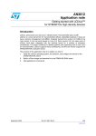
Configurator immediately. The main view is divided into two sections:
1 - Project Explorer view: Tofino SAs, Asset Templates, Assets,
Protocols, and Special Rules are listed in a tree format similar to the way
that files are displayed in Windows Explorer. Any object in the Project
Explorer view can be clicked to display its information in the Details view.
Clicking the root folder will display a table of defined objects of that type.
For example, clicking the Assets folder will display a table listing the
assets defined in the project.
2 - Details view: The details of what is selected in the Project Explorer
view display here. This is where you can edit particular values for an
object.
12
Tofino Configurator
Release V2.00 05/2014
Introducing the Tofino Configurator
1.1 Navigating the Tofino Configurator
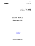
The Tofino Configurator has a toolbar that allows you to perform actions on
the objects in a project.
The toolbar contains three sections:
1 - Project edit commands: This section appears at the far left of the
toolbar and is for commands related to managing project files and their
data. It includes:
Create new Projects, Assets, Asset Templates, Protocols, or Tofino
SAs using a wizard
Open an existing project
Save a project
Import predefined Asset Templates, Protocols, Special Rules, and
Security Profiles
Cut, Copy, Paste, and Delete objects and fields
2 - Context commands: This section appears in the center of the toolbar
and is for commands related to the content that is currently being worked
on. The commands that appear here change depending on the type of
object selected in the Project Explorer view.
3 - Help and Configuration commands: This section appears at the far
right of the toolbar and is for:
Audit Logs: Viewing and managing the audit system
Preferences: Setting configurations, such as the location of the audit
file
Licensing: Managing your Tofino Configurator and LSM licenses
Help: Displaying the online help and Tofino Configurator product
information
Tofino Configurator
Release V2.00 05/2014
13
Introducing the Tofino Configurator
14
1.1 Navigating the Tofino Configurator
Tofino Configurator
Release V2.00 05/2014
Nine Steps to a Secure Control
System
2 Nine Steps to a Secure Control
System
The Tofino Configurator was designed to make the installation of security
firewalls in an industrial control system as simple as possible. The following
nine steps describe how to install and configure your Tofino Industrial
Security Solution.
Tofino Configurator
Release V2.00 05/2014
15
Nine Steps to a Secure Control
System
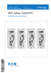
Install the Tofino Configurator on your computer.
Create a project.
Define the Tofino SAs for your project.
This information will be used to configure the actual Tofino SAs that will
be installed on your network.
Define assets for your project.
These objects represent both real network entities (such as HMIs and
PLCs) and virtual entities (such as Broadcast Addresses) on your
network. They are used to simplify tasks like creating firewall rules.
Define firewall rules for your Tofino SAs.
These use the assets you created earlier, along with predefined protocols
and special rules that are supplied with the Tofino Configurator, to
determine what network traffic the Tofino SA will allow or block. The
various Deep Packet Inspection (DPI) Enforcer modules are accessed
through the Firewall selection.
Configure the Event Logger (optional).
Enter the details for your syslog server where you want Tofino SA alarms
and events sent. You can also configure the Tofino SA to save logs locally
on the Tofino SA for later offloading via a USB storage device.
Install your Tofino SA hardware.
The Tofino SA gets installed on the network between the device(s) to be
protected and the rest of the network.
Apply the configuration settings to the Tofino SAs in the field.
Depending on the options you have purchased, you can transfer the
configuration data from the Tofino Configurator to the Tofino SA(s) over
the network or using a USB storage device.
Verify the configuration.
Retrieves the configuration load reports sent over the network or from the
USB storage device that was used to load configurations onto one or
more Tofino SAs. This will allow you to record the configuration of Tofino
SAs in the field and save it in your project.
You have successfully installed the Tofino Industrial Security Solution and
significantly improved the security of your process network.
Note: The Tofino SA will pass network traffic freely during the initial
configuration or when its configuration is being updated. Firewall rules take
effect after completion of the initial configuration or update of the Tofino SA
so that network operations are not affected before the full rule set can be
loaded. A typical configuration load will finish in approximately 30 seconds.
16
Tofino Configurator
Release V2.00 05/2014
Installing Your Tofino Configurator
3 Installing Your Tofino
Configurator
This section details the procedure for installing the Tofino Configurator on a
computer that has not previously had the Tofino Configurator installed on it.
Prior to installing your Tofino Configurator software, please verify that you
have the following materials ready:
Tofino Configurator Installer CD
License Activation Key (a string of 25 letters and numbers, such as
X4QP9-RMNRQ-B59SD-AG5H6-KSFRW)
Tofino Configurator
Release V2.00 05/2014
17
Installing Your Tofino Configurator
3.1 Running the Tofino Configurator
Installer
3.1 Running the Tofino
Configurator Installer
Running the Tofino Configurator installer launches the installation wizard.
Work through the pages of the wizard to configure the installation, accept the
license agreement, and activate your license.
To install the Tofino Configurator, you need a Windows user account with
Administrator permissions.
Run the Tofino Configurator installer from the CD.
Follow the on-screen instructions to install the Tofino Configurator.
The Tofino Configurator installation wizard walks you through the steps to
configure your installation:
Accept the license agreement
Specify the installation type
Select a destination folder
Add program icons to specific folders
Create shortcut icons
Click "Next" and "Back" to move between the pages of the wizard.
On the Start Installation page of the wizard, review the settings you
selected.
18
Tofino Configurator
Release V2.00 05/2014
Installing Your Tofino Configurator
3.1 Running the Tofino Configurator
Installer
Clicking "Next" on this page begins the installation.
Note: To install the Tofino Configurator with the default installation
settings, click "Install" in the bottom left corner at any time.
To complete the installation, click "Finish" on the final page of the wizard.
If this is a new installation of the Tofino Configurator, the program displays
the Activate Your License dialog box.
Tofino Configurator
Release V2.00 05/2014
19
Installing Your Tofino Configurator
3.1 Running the Tofino Configurator
Installer
Enter your License Activation Key and contact information. Click "OK".
The Tofino Configurator will start automatically if you selected the "Start
the Tofino Configurator" check box on the final page of the wizard.
The installation is complete and your license has been activated.
Additional configuration steps may be required depending on who will be
using this program.
A Windows user with administrator permissions has full access to all
Tofino Configurator functionality. To enable Windows users without
Administrator permissions to use the application, perform the following
additional steps.
By default, the Tofino Configurator preferences and audit log files are
located in C:\ProgramData\Tofino Security\Tofino Configurator. Nonadministrator users need permission to write to this location. Using
Windows security, allow Write access to this folder. You can choose to
relocate the audit log file to a write-accessible location (see
“Customizing Program Settings and Preferences”) but you cannot
move the preferences file.
To give non-administrator users full access to a Tofino Configurator
project, save the project file (.tpf) to a folder that allows them
Administrator or Read/Write access. To limit their functionality in a
project, save the project file to a folder that allows them Read-Only
access. See “Managing User Logging, Access, and Privileges”.
If you plan to use the NetConnect Loadable Security Module (LSM),
you need to create firewall exceptions to open ports for both the TCP
and UDP protocols. Tofino‘s defined port is 6689.
Register the Tofino Configurator in the Tofino Customer Portal
20
Tofino Configurator
Release V2.00 05/2014
Installing Your Tofino Configurator
3.1 Running the Tofino Configurator
Installer
(http://www.tofinosecurity.com/licensing).
Tofino Configurator
Release V2.00 05/2014
21
Installing Your Tofino Configurator
22
3.1 Running the Tofino Configurator
Installer
Tofino Configurator
Release V2.00 05/2014
Projects
4 Projects
The Tofino Configurator uses project files to coordinate one or more Tofino
SAs that are being used for a common facility or project. Each project file
contains the configurations of the Tofino SAs it is managing along with other
information, such as network assets and common protocols.
When you start the Tofino Configurator, you will be asked if you would like to:
Create a new project (see “Creating a New Project” on page 25)
Open an existing project
Once you create a project file, that file will be visible for you to open from the
start-up screen. The last five projects opened display here. You can set a
specific project file as the default project so that it automatically opens every
time you start the Tofino Configurator. After you do this, the start-up screen
will no longer appear. You set and clear the default project with the
Preferences feature (see “Customizing Program Settings and Preferences”
on page 128).
Once you load a project file, you can view the project details and protection
information. This includes the project name; the name and location of the
project file on the computer; the revision number of the project; the users who
created and last modified the project file; the company name; the project
protection settings; and the administrator protection setting.
Tofino Configurator
Release V2.00 05/2014
23
Projects
24
Tofino Configurator
Release V2.00 05/2014
Projects
4.1 Creating a New Project
4.1 Creating a New Project
To begin using the Tofino Configurator, create a project. You can do this from
the start-up screen or from within the application. Create as many projects as
you need for your site. While only one project is required, you may choose to
segregate your network into smaller projects.
As part of project creation, you can restrict access to the project file with the
License Activation Key, a password, or both. Each time the project is saved,
the license key and/or the password will be used to encrypt the project file.
Anyone who acquires the project file will be unable to access the content
without first providing the appropriate key and/or password. When a user
attempts to open the project in the Tofino Configurator, the license key will
automatically be read from the program, but the user will be prompted to
enter the password.
As an extra layer of protection, you can set an Administrator password. This
helps prevent users from performing certain functions without approval from
the Administrator. When this password is set, users require Administrator
permission to change the Project Protection settings or move the project file.
For more information on project protection, see “Managing User Logging,
Access, and Privileges”.
On the start-up screen, click "Create New Project".
Tofino Configurator
Release V2.00 05/2014
25
Projects
4.1 Creating a New Project
Note: Once you set a default project to open automatically, the start-up
screen no longer appears.
Alternately, within the application, click the New icon in the toolbar to open
the wizard, then select "Project" and click "Next". If you have another
project open, a message informs you that it will be closed. You will be
prompted to save the project, if necessary.
Whether you create the project from the start-up screen or from within the
application, the New Project Wizard opens. Here you enter the details for
the project you are creating.
Enter a project name and a company name. Click "Next".
Select how you want to restrict access to the project file: "License
Activation Key" and/or "Password".
If you choose password protection, complete the "Password" and
"Confirm Password" fields. Create a password that is at least 6 characters
long and includes uppercase, lowercase, and special characters.
26
Tofino Configurator
Release V2.00 05/2014
Projects
4.1 Creating a New Project
Note: If you leave both check boxes empty, all users will be able to access
the information in the .tpf project file.
To restrict access to the project file, you select the License Activation Key
option. When selected, the project file will open exclusively on a machine
with a matching License Activation Key. You can disable this option when
you need to share the project file with technical support or a person in your
company who is running a different copy of the Tofino Configurator.
Click "Next".
Set an optional administrator password. Select the "Use Administrator
Password" check box then complete the "Password" and "Confirm
Password" fields.
Create a password that is at least 6 characters long and includes
uppercase, lowercase, and special characters.
Click "Finish". The project is created but has not yet been saved.
Click the Save icon in the toolbar. The standard Windows Save As dialog
box opens.
Select a location on your computer to store the project file and enter a
name for the project. The filename will be appended with .tpf.
Click "Save".
Tofino Configurator
Release V2.00 05/2014
27
Projects
4.2 Opening an Existing Project
4.2 Opening an Existing Project
You can open an existing project file when you start the Tofino Configurator
or you can open a project from within the application.
On the start-up screen, click "Open Project".
For convenience, the start-up screen displays the last five projects
opened. If the project you want to open appears in this list, click it to load
the project.
Note: Once you set a default project, that project will load automatically
when you start the Tofino Configurator.
Alternately, within the application, click the Open icon in the toolbar. If you
have another project open, a message informs you that it will be closed.
You will be prompted to save the project, if necessary.
Locate the project file on your computer. The filename will be appended
with .tpf.
Click the file you want to open to select it. Click "Open".
When the project is password protected, the program prompts you to
enter the password. Type the project password and click "OK".
28
Tofino Configurator
Release V2.00 05/2014
Projects
4.3 Editing Project Details
4.3 Editing Project Details
You can view and edit the details of the project you currently have open in
the Tofino Configurator. You can also change the protection settings and
passwords.
Click the project name in the Project Explorer view. The details for the
current project display.
Update the Project Details section as necessary.
Project Name: A user editable project name.
Project File: The name of the project file with the location it was loaded
from or lasted saved to. This is also the location where the project will
be stored the next time it is saved. This field displays <unsaved> for
new, unsaved projects.
Project Revision: The number of the current version of this project,
along with a specially calculated hash code to reduce the chance of
accidental duplication of revision numbers. The project revision
number is incremented each time the project is saved.
Creator: The user who created the project. This is the Windows user
name of the person who was logged in when the project was created.
Tofino Configurator
Release V2.00 05/2014
29
Projects
4.3 Editing Project Details
Last Modified By: The user who last saved the project. This is the
Windows user name of the person who was logged in when the project
was last saved.
Company: A user editable company name.
In the Project Protection section, change how you want to restrict access
to the project file. You can add protection settings, remove protection
settings, and change the current password.
Click a selected check box to turn off a protection setting.
Click an empty check box to turn on a protection setting.
Click "Change Password" to edit the current project protection
password, if one is set. You will need to enter the current password
and then enter and confirm a new password. Create a password that
is at least 6 characters long and includes uppercase, lowercase, and
special characters. Click "OK".
In the Administrator Protection section, change the administrator setting.
To make yourself the project administrator, enable the check box if it
is not already selected. Set a password and click "OK".
To remove protection at this level, clear the check box. You will be
prompted to confirm the action; click "OK". When prompted, enter the
current password and click "OK" to confirm that you have permission
to remove the protection.
To edit the current password, click "Change Administrator Password".
You will need to enter the current password and then enter and confirm
a new password. Create a password that is at least 6 characters long
and includes uppercase, lowercase, and special characters. Click
"OK".
Click the Save icon in the toolbar.
If this is a new project that has not been saved, select a location on your
computer to store the project file, enter a name for the project, and click
"Save".
30
Tofino Configurator
Release V2.00 05/2014
Projects
4.4 Deleting a Project
4.4 Deleting a Project
You delete a project from outside the Tofino Configurator. Delete the project
file as you would any Windows file.
Open Windows Explorer and locate the project file on your computer.
Select the .tpf file you want to delete.
Press DELETE. A message prompts you to confirm the deletion.
Click "Yes".
Tofino Configurator
Release V2.00 05/2014
31
Projects
4.5 Duplicating a Project
4.5 Duplicating a Project
The Save As feature lets you create a copy of your project file. You can also
use this feature to save a project file to a new location on your computer.
Open the project you want to duplicate.
Open the Save menu and click "Save As".
Select a location on your computer to store the new project file.
Edit the filename for the project.
Click "Save".
If an administrator password is set for this project, then administrator
approval is required to save the project to a new location. To continue you
need the project’s administrator password.
32
Tofino Configurator
Release V2.00 05/2014
Tofino SAs
5 Tofino SAs
Tofino Security Appliances, referred to as Tofino SAs, are the hardware
devices installed on your live network. They also exist in the Tofino
Configurator, where you create a Tofino SA to represent each physical
device being installed. You configure the devices in the Tofino Configurator
and then transfer the configuration data to the devices, either over the
network or with a USB device.
From the Tofino SAs item in the Project Explorer view, you can create, edit,
and delete the configuration data for multiple Tofino SAs contained in a single
project.
By selecting a specific Tofino SA in the Project Explorer view, you can do the
following:
Create a new Tofino SA
View and edit the Tofino SA configuration
Delete a Tofino SA
Create a configuration that can be loaded onto a Tofino SA device in the
field
Verify the configuration that is installed on a Tofino SA
Normally you will perform the last two tasks once your Tofino SA is fully
configured. After defining a Tofino SA in the project, you may also need to
configure event logging and define firewall rules.
The Discovery item in the Project Explorer view lets you search for existing
Tofino SAs already configured on your network.
Tofino Configurator
Release V2.00 05/2014
33
Tofino SAs
5.1 Defining the Tofino SAs
5.1 Defining the Tofino SAs
Within a project, you define a Tofino SA for each Tofino SA hardware device
that will be installed on your network. The two most common ways to define
a Tofino SA are:
Create a new Tofino SA from scratch
Discover Tofino SA devices already configured on the network
You can also copy and paste a Tofino SA within the same project or across
different projects. Once you paste the Tofino SA into the project, edit the
settings as necessary.
The Tofino SAs you define appear in the Project Explorer view beneath the
item Tofino SAs. Click this top level item to display the current folder structure
and the defined Tofino SAs.
You can create a folder hierarchy to organize your Tofino SAs. Use the New
Folder feature in the toolbar to create folders. You can use the Cut and Paste
actions in the toolbar to move the devices.
34
Tofino Configurator
Release V2.00 05/2014
Tofino SAs
5.1.1
5.1 Defining the Tofino SAs
Creating a New Tofino SA
Create as many Tofino SAs in the project as are needed to represent each
physical device being installed on the network.
Click "Tofino SAs" in the Project Explorer view and then click "New Tofino
SA" in the toolbar.
Alternately, open the New menu in the toolbar and click "Tofino SA".
The New Tofino SA wizard opens.
Enter the Tofino ID. This number is found on the face of the Tofino SA
device.
If you don‘t know the Tofino ID of your appliance you can enter a
temporary ID of 00:00:00:00:00:XX, where XX is any two digit
number. This lets you configure the Tofino SA without the actual ID
number. However, you will receive a message indicating that you need to
enter a correct Tofino ID in order to apply the configuration to a Tofino SA.
Enter information to identify this specific Tofino SA device in the "Name",
"Description", "General Location", and "Specific Location" fields.
Select the mode—Operational or Test—that you want the Tofino SA
to run in when the configuration is loaded. Click "Next".
Note: During commissioning, confirm that the Tofino SA is set to Test
mode to allow validation of the firewall rules without dropping needed
traffic. Once the rules have been validated, set the Tofino SA to
Operational mode. For more information on using Test mode, see “Using
Tofino Test Mode to Validate Firewall Rules”.
Tofino Configurator
Release V2.00 05/2014
35
Tofino SAs
5.1 Defining the Tofino SAs
Name the Tofino SA interfaces and set the configuration of each interface.
Click "Next".
On the final page of the wizard, select the LSMs you want to activate for
this Tofino SA.
NetConnect LSM: The Tofino NetConnect LSM enables the Tofino
Configurator and the Tofino SA to communicate over the network. This
allows you to perform certain tasks, such as applying and verifying
configuration, from your PC without having to physically visit the Tofino
SA in the field.
Firewall LSM: The Tofino Firewall LSM checks the communications
on your control network against a list of traffic rules that are defined by
your controls engineer. Any communication that is not on the allowed
list will be blocked and reported by the Firewall LSM.
Event Logger LSM: The Tofino Event Logger LSM records security
events and alarm information. It can record and back up this
information simultaneously to both a remote IT syslog server and a
non-volatile memory in the Tofino SA.
36
Tofino Configurator
Release V2.00 05/2014
Tofino SAs
5.1 Defining the Tofino SAs
Modbus TCP Enforcer LSM: The Tofino Modbus TCP Enforcer LSM
checks every Modbus command and response against a list of allowed
commands defined by your controls engineer. Any command that is
not on the allowed list, or any attempt to access a register or coil that
is outside the allowed range, will be blocked and reported. It also filters
traffic based on the validity of the Modbus TCP messages, screening
out messages that have been either deliberately or accidentally
malformed.
OPC Classic Enforcer LSM: The Tofino OPC Classic Enforcer LSM
inspects, tracks, and helps secure every connection that is created by
an OPC application. It dynamically opens only the TCP ports that are
required for each connection, and only between the specific OPC
client and server that created the connection. It also filters traffic based
on the validity of the OPC Classic messages, screening out messages
that have been either deliberately or accidentally malformed.
EtherNet/IP Enforcer LSM: The Tofino EtherNet/IP Enforcer LSM
checks EtherNet/IP explicit messages for CIP objects or services, and
compares them against selected lists of allowed commands. This
gives you the capability to restrict traffic to data read-only, data
read/write, or programming messages to PLC and other devices, as
required for your security strategy. It also filters traffic based on the
validity of the EtherNet/IP messages, screening out messages that
have been either deliberately or accidentally malformed.
Click "Finish".
The new Tofino SA appears in the Project Explorer view.
Expand the Tofino SA and click "General" to display the General settings
page.
See the reference section “Tofino SA Fields” for a detailed description of
the fields on this page.
Confirm the information for this device is correct. Check the
Communications section, which defaults to "Both Network and USB".
Change this setting as necessary.
You can specify whether you want to transfer configuration data to the
Tofino SA device over the network or with a USB device. If you do not
have a license for the NetConnect LSM, choose "USB Only".
Tofino Configurator
Release V2.00 05/2014
37
Tofino SAs
5.1.2
5.1 Defining the Tofino SAs
Discovering an Existing Tofino SA
The Discovery feature lets you search your network for new and existing
Tofino SA devices. By scanning IP address ranges, the Tofino SAs can be
discovered and then added to your project.
When working with multiple Tofino SAs, you may want to organize them in
folders. You can create the folder hierarchy before you discover the devices
or when you enter the scan details. To create folders prior to configuring the
scan settings, use the New Folder feature in the toolbar. Select "Tofino SAs"
or an existing folder in the Project Explorer view to display this button.
In the Project Explorer view, expand the Tofino SA you are working with
and click "Discovery".
On the Tofino Discovery page, you configure a scan on the left side of the
page. On the right side, you view the progress and results of the scan.
In the "Start IP" and "End IP" fields, enter the starting and ending IP
addresses for the range you want to scan.
The number of addresses to be scanned and the estimated runtime is
calculated and displayed in the Results section.
Note: When setting scan ranges, it is helpful to keep them as small as
possible as scanning is deliberately slow so that it does not impact the
process network in any way. One scan message is sent each second, so
scanning larger ranges (greater than 5000 addresses) may take several
hours.
38
Tofino Configurator
Release V2.00 05/2014
Tofino SAs
5.1 Defining the Tofino SAs
Specify the folder where you want to save the Tofino SAs that are
discovered with this scan.
To display the existing folders, click the button to the right of the
"Destination Folder" field.
To create a new folder beneath the currently selected folder, click the
Add button (+). Enter a name for the new folder and click "OK".
Select the destination folder for discovered Tofino SAs.
Click "OK".
To run the scan repeatedly, select the "Continuous Scan" check box. The
scan will run until you manually stop it.
This feature enables you to start the scan before the Tofino SA devices
are actually installed. As they are installed on the network, the scan will
discover them.
To begin the scan, click "Start".
To pause the scan at any time, click "Pause". The scan is held at this point
until you click "Start" to begin it again. The "Duration" field displays how
long the scan has been running since the last time "Start" was clicked.
To return the scan configuration fields to the default values, click "Reset".
The progress of the scan displays in the Results section. There are five
states:
Ready: The scan is configured but has not been started.
Scanning: The scan is in progress.
Complete: The entire address range has been scanned.
Paused: The user has paused the scan.
Rescanning: The entire address range has been scanned at least
once and is being scanned again. This state relates to the "Continuous
Scan" feature. The "Iteration" value indicates how many times the
range has been scanned.
As devices are discovered, they appear in the Project Explorer view at the
specified location. The General settings page is populated with basic device
information: Tofino ID, Name, and Hardware Type. A network connection is
automatically attempted and, if successful, provides additional device details.
Tofino Configurator
Release V2.00 05/2014
39
Tofino SAs
5.2 Editing a Tofino SA
5.2 Editing a Tofino SA
Selecting or expanding a Tofino SA in the Project Explorer view displays links
that let you navigate to pages where you can edit the device configuration.
The configuration and setting options available for a Tofino SA will depend
on its associated LSMs. Typically, the available settings include:
General settings: Configure the general settings for the selected Tofino
SA. This includes general information, communication parameters, and
LSM selection.
Event Logger LSM settings: Configure alarm and event logging for the
selected Tofino SA.
Firewall LSM settings: Configure firewall rules for the selected Tofino SA.
When you copy a Tofino SA from another project, review the configuration
settings to verify that it is set up properly for the new location.
In the Project Explorer view, expand the Tofino SA you want to work with
and click "General".
The page displayed shows the general configuration settings for this
Tofino SA.
40
Tofino Configurator
Release V2.00 05/2014
Tofino SAs
5.2 Editing a Tofino SA
Update theTofino SA configuration as necessary.
See the reference section “Tofino SA Fields” for a detailed description of
the fields on this page.
Click the Save icon in the toolbar.
Tofino Configurator
Release V2.00 05/2014
41
Tofino SAs
5.3 Deleting a Tofino SA
5.3 Deleting a Tofino SA
Delete a Tofino SA if you no longer need it in the current project.
The Tofino SA in your Tofino Configurator project is a virtual representation
of the physical Tofino SA device. Special keys are stored in both of these
locations to enable communication between them. Deleting a Tofino SA from
the project deletes its configuration data, including the special keys. This will
block any future network communication between the Tofino Configurator
and that Tofino SA device until a factory reset is performed on the Tofino SA
device. The factory reset clears the second of the two keys and opens the
door for a new Tofino Configurator/Tofino SA pairing to be established.
In the Project Explorer view, click the Tofino SA you want to delete.
Click the Delete icon in the toolbar.
When the Communications setting is "Network Only" or "Both USB and
Network", a message asks if you want to perform a factory reset on the
Tofino SA. Click "Yes". The Tofino Configurator automatically resets the
Tofino SA to the factory settings.
When the Communications setting is "USB Only", you need to perform the
factory reset manually. See “Factory Resetting Your Tofino SA”.
A message prompts you to confirm the deletion. Click "OK" to proceed.
42
Tofino Configurator
Release V2.00 05/2014
Assets
6 Assets
In the Tofino Configurator, assets represent the real world devices and
systems on the control network. An asset can represent a physical device,
such as a PLC, a computer, or network equipment. It can also represent a
virtual asset, such as a broadcast address range, a network, or a multicast
address. This provides flexibility when creating firewall rules.
By selecting a specific asset in the Project Explorer view, you can do the
following:
Create a new asset from scratch
Create a folder
View and edit the asset's details
Create an asset template from the selected asset
Delete an asset
You can create a new asset either from scratch or from a template.
Computer, Controller, Device, and Network Equipment
Assets
Most assets used in the Tofino Configurator are real devices. These
typically use messages known as Unicast messages. A Unicast message
is network traffic directed from a specific device to another specific device.
When you define an asset to be a computer, controller, device, or network
equipment, the Tofino Configurator assumes it is a physical device on
your network and helps create rules appropriate for that type of device.
Network Assets
Network assets are a virtual representation of the devices contained in a
specific network or subnetwork. When you define an asset to be a
network, the Tofino Configurator assumes it is a collection of devices on
your network that belong to a group of IP addresses known as a subnet.
Thus, if you use a network asset in a rule, the Tofino Configurator helps
create rules that allow or deny traffic from that range of addresses.
Tofino Configurator
Release V2.00 05/2014
43
Assets
Broadcast and Multicast Assets
In most networks there are messages that are sent to a general address
and are expected to be received by everyone on the network. These are
called Broadcast and Multicast messages. The Tofino Configurator has
special assets designed to handle these types of messages.
Broadcast: This asset represents an address that is used for IP
broadcasts. Broadcast packets, which are a normal part of network
operation, are transmitted by a device to a broadcast address that
many devices listen to. For example, IP networks use broadcasts to
resolve network addresses using Address Resolution Protocol (ARP).
The exact broadcast address is dependent on the subnet defined for
a given network. If the node address is 192.168.1.1 the broadcast
address might be 192.168.1.255, depending on the subnet of the
node. This type of asset is required if you wish to provide broadcast
filtering rules in the Firewall LSM.
Multicast: This asset represents an address that is used for IP
multicasts. Multicast packets are transmitted to a multicast address
that a set of devices listen to. Typically these are IP addresses in the
range between 224.0.0.0 through 239.255.255.255 and depend on the
manufacturer of controller hardware, the protocols in use, and the
network configuration. For example, 239.192.22.121 is often used in
EtherNet/IP networks, while 234.5.6.7 is often used with Fault Tolerant
Ethernet Systems. This is required if you wish to provide multicast
filtering rules in the Firewall LSM.
44
Tofino Configurator
Release V2.00 05/2014
Assets
6.1 Asset Templates
6.1 Asset Templates
An asset template is a tool to help you create multiple assets quickly. It
contains predefined fields that can be used to rapidly create similar assets.
For example, if you have ten PLCs in your plant that are a similar make and
model, you can create an asset template (or use a pre-existing template) to
represent that type of PLC. Then you can quickly generate assets to
represent the ten similar PLCs.
The Tofino Configurator comes with a number of templates preloaded for
common automation products. You can also import new templates or create
templates of your own.
By selecting a specific asset template in the Project Explorer view, you can
do the following:
Create a new asset template
Create a folder
Create a new asset from the selected template
View and edit the asset template's details
Delete the asset template
The templates that you create appear in the Project Explorer view in the
Asset Templates folder.
You can create a folder hierarchy to organize your templates. Use the New
Folder feature in the toolbar to create folders. You can create a template in a
specific folder, or you can use the Cut and Paste actions in the toolbar to
relocate templates.
Some templates are factory defined, and cannot be cut or deleted.
Tofino Configurator
Release V2.00 05/2014
45
Assets
6.1.1
6.1 Asset Templates
Creating an Asset Template
Create as many asset templates in a project as you need to simplify the
process of creating assets. When you have several assets that are similar, it
will save time to create a template containing the common information and
then use that to create your assets.
You can create rule profiles for asset templates. When you create a template
you can specify the protocols that this type of asset typically uses, along with
how you want those protocols managed. The New Firewall Rule Wizard can
use this information to automatically create rules for the assets created from
this template. For more information, see “Rule Profiles”.
46
Tofino Configurator
Release V2.00 05/2014
Assets
6.1 Asset Templates
Note: To add rule profiles to preloaded templates, first make a copy of the
template and then add the rule profiles.
Click "Asset Templates" in the Project Explorer view and then click "New
Asset Template" in the toolbar.
Alternately, open the New menu in the toolbar and click "Asset Template".
Note: This creates an asset template at the top level. Select a folder
before clicking "New Asset Template" to create the template in a specific
location. Use the New Folder feature in the toolbar to create folders to
organize the templates.
The New Asset Template dialog box opens.
Enter a name for this asset template and select the type of asset it
represents.
Complete the remaining fields (optional). Generally, you will not complete
the Communications section. A user will add these details when creating
a specific asset from this template.
Click "Finish".
The program adds the new template in the specified location in the Project
Explorer view. The details view displays the template configuration.
Tofino Configurator
Release V2.00 05/2014
47
Assets
6.1 Asset Templates
You can now define rule profiles. This lets you specify the protocols that
an asset uses, along with how you want the protocols managed. The New
Firewall Rule Wizard uses this information to automatically create rules
for the asset. For more information, see “Rule Profiles”.
To open the New Rule Profile Wizard, click "Add Rule Profile" beneath the
Rule Profiles table.
Select the type of rule you want to create: standard or special. If you are
creating a special rule, you also select a rule type from the list provided.
Click "Next".
Define the rule profiles.
Expand the folders and select the protocols you want to use. Use
SHIFT+click to select a range of protocols; use CTRL+click to select
multiple protocols out of sequence. The Tofino Configurator creates a
rule profile for each protocol selected.
Set the permission. This tells the firewall what to do with a packet that
matches the rule profile: allow it to pass ("Allow") or stop it from
passing ("Deny"). The "Enforcer" option inspects and filters the traffic
using Deep Packet Inspection. This option is appropriate solely for the
Enforcer protocols.
To create a log each time the rule is triggered, select the "Enable
Logging" check box.
Click "Finish".
The profiles created appear in the Rule Profiles table.
48
Tofino Configurator
Release V2.00 05/2014
Assets
6.1 Asset Templates
Select the rule protocol in this table and finish configuring it in the Rule
Details section.
You can adjust advanced settings, such as traffic rate limiting, for most
rule profiles. Additional settings for the selected rule profile are displayed
in one or more tabs below the table.
Click the Save icon in the toolbar.
See the reference section “Asset and Asset Template Fields” for a
detailed description of the fields on this page.
6.1.2
Deleting an Asset Template
Delete an asset template if you no longer need it in the current project. The
templates reside in the "Asset Templates" folder.
In the Project Explorer view, locate the asset template you want to delete
and click it in the tree to select it.
View the details to verify that this is the correct template.
Click the Delete icon in the toolbar. A message prompts you to confirm the
deletion.
Click "OK" to proceed.
Tofino Configurator
Release V2.00 05/2014
49
Assets
6.2 Creating Assets
6.2 Creating Assets
To build your asset library, you can create assets from scratch or from
existing templates. Asset templates contain default asset details, allowing
you to create similar assets quickly.
You can also copy and paste an asset or asset template into the Assets
folder to create an asset. However, this does not run the wizard. To make the
asset unique, you need to edit the details manually.
6.2.1
Creating an Asset from Scratch
Creating an asset involves defining its general information, communication
parameters, and rule profiles.
You can create as many assets as needed for your project. When working
with multiple assets, you may want to organize them in folders. Use the New
Folder feature in the toolbar to create the folder hierarchy.
In the Project Explorer view, expand "Assets" and click the folder where
you want the new asset to reside. To create the asset at the top level, click
"Assets".
Click "New Asset" in the toolbar.
Alternately, open the New menu in the toolbar and click "Asset".
The New Asset wizard opens.
50
Tofino Configurator
Release V2.00 05/2014
Assets
6.2 Creating Assets
Enter a name for this asset and select its type.
Complete the remaining fields to identify the asset (optional). Click "Next".
Enter an IP address and/or a MAC address for this asset. This information
will be used by the Tofino Configurator when creating firewall rules for this
asset.
Click "Finish".
The new asset appears in the specified location in the Project Explorer
view. The details view displays the asset details.
Tofino Configurator
Release V2.00 05/2014
51
Assets
52
6.2 Creating Assets
You can now define rule profiles. This lets you specify the protocols that
an asset uses, along with how you want the protocols managed. The New
Firewall Rule Wizard uses this information to automatically create rules
for the asset. For more information, see “Rule Profiles”.
To open the New Rule Profile Wizard, click "Add Rule Profile" beneath the
Rule Profiles table.
Select the type of rule you want to create: standard or special. If you are
creating a special rule, you also select a rule type from the list provided.
Click "Next".
Define the rule profiles.
Expand the folders and select the protocols you want to use. Use
SHIFT+click to select a range of protocols; use CTRL+click to select
multiple protocols out of sequence. The Tofino Configurator creates a
rule profile for each protocol selected.
Set the permission. This tells the firewall what to do with a packet that
matches the rule profile: allow it to pass ("Allow") or stop it from
passing ("Deny"). The "Enforcer" option inspects and filters the traffic
using Deep Packet Inspection. This option is appropriate solely for the
Enforcer protocols.
To create a log each time the rule is triggered, select the "Enable
Logging" check box.
Click "Finish".
The profiles created appear in the Rule Profiles table.
Select the rule protocol in this table and finish configuring it in the Rule
Details section.
Tofino Configurator
Release V2.00 05/2014
Assets
6.2 Creating Assets
You can adjust advanced settings, such as traffic rate limiting, for most
rule profiles. Additional settings for the selected rule profile are displayed
in one or more tabs below the table.
Click the Save icon in the toolbar.
See the reference section “Asset and Asset Template Fields” for a
detailed description of the fields on this page.
6.2.2
Creating an Asset from a Template
Use a template to quickly create an asset with default values already
completed.
Assets created from a template are placed in the Assets folder in alphabetical
order. You can reorganize the assets into specific folders as needed.
In the Project Explorer view, expand "Asset Templates" and locate the
template you want to use to create an asset.
Click the asset template to select it and click "New Asset from Template"
in the toolbar.
The New Asset wizard opens with most fields completed.
Change the entry in the "Name" field to identify the asset you are creating.
Complete the remaining fields to identify the asset (optional). Click "Next".
Tofino Configurator
Release V2.00 05/2014
53
Assets
6.2 Creating Assets
Enter an IP address and/or a MAC address for this asset. This information
will be used by the Tofino Configurator when creating firewall rules for this
asset.
Click "Finish".
The program adds the new asset to the Assets folder in the Project
Explorer view. The Rule Profiles table displays any rule profiles
configured for the template.
To relocate the asset to another folder, use the Cut and Paste actions in
the toolbar.
Click the Save icon in the toolbar.
See the reference section “Asset and Asset Template Fields” for a
detailed description of the fields on this page.
54
Tofino Configurator
Release V2.00 05/2014
Assets
6.3 Editing an Asset or an Asset
Template
6.3 Editing an Asset or an Asset
Template
Selecting an asset or an asset template in the Project Explorer view displays
the configuration details for the selected item. From here you can edit the
settings. This page includes general information, communication
parameters, and rule profiles.
The Rule Profiles table displays the rule profiles created for the selected
asset or template. You can make changes directly on this page: in the table
and in the Rule Details section.
In the Project Explorer view, click the asset or template you want to edit.
The configuration details are displayed.
Update the fields in the General and Communications sections.
Note: Generally, you will not complete the Communications section. A
user will add these details when creating a specific asset from this
template.
Tofino Configurator
Release V2.00 05/2014
55
Assets
6.3 Editing an Asset or an Asset
Template
In the Rule Profiles table, click the cell you want to edit and make the
necessary change in the table. Depending on the cell selected, you will be
able to:
Change the state of a check box
Select an entry in a list
Open a dialog box and select from a list of appropriate values
Enter text
To delete a rule profile, select it in the table and click the Remove button
(x) beneath the table.
On the General and Enforcer tabs in the Rule Details section, update the
settings as necessary for the currently selected rule profile.
Click the Save icon in the toolbar.
See the reference section “Asset and Asset Template Fields” for a
detailed description of the fields on this page.
56
Tofino Configurator
Release V2.00 05/2014
Assets
6.4 Creating an Asset Template from
an Existing Asset
6.4 Creating an Asset Template
from an Existing Asset
You may find yourself in the situation where you need to create several
assets that are similar to one you already have in your project. You can
create an asset template from that existing asset. This will then allow you to
quickly create the additional assets from the template.
In the Project Explorer view, locate the asset you want to use as the basis
for an asset template.
View the details to verify that this is the correct asset.
In the Project Explorer view, right click that asset and click "Copy".
Right click the folder where you want the new asset template to reside and
click "Paste". You can place it in the Asset Templates folder or one of the
subfolders.
The asset appears in the specified location.
In the Project Explorer view, click the new asset template to display its
details. Make any changes necessary so that it can be used to quickly
create assets.
Click the Save icon in the toolbar.
Tofino Configurator
Release V2.00 05/2014
57
Assets
6.5 Deleting an Asset
6.5 Deleting an Asset
Delete an asset if it no longer belongs in the current project. The assets
reside in the Assets folder or in a subfolder.
In the Project Explorer view, locate the asset you want to delete and click
it in the tree to select it.
View the details to verify that this is the correct asset.
Click the Delete icon in the toolbar.
If the selected asset is referenced in a firewall rule, you will receive a
message with three options. You can choose to cancel the deletion;
delete the asset and replace the references to it with its current address;
or delete the asset and fix the resulting errors later.
When you choose to delete the asset, a message prompts you to confirm
the action. Click "OK" to proceed. Canceling the deletion at this prompt
will not reinstate the asset in any firewall rules from which it was removed.
58
Tofino Configurator
Release V2.00 05/2014
Firewall Rules
7 Firewall Rules
A firewall is a mechanism used to control and monitor traffic between two
networks (or two portions of the same network) to help protect devices on the
network. It compares the traffic passing through the firewall to a predefined
set of rules, discarding traffic that does not meet the rule criteria. In effect, it
is a filter that blocks unwanted network traffic and places limitations on the
amount and type of communication that occurs between devices (or
networks) in need of protection and other systems, such as the corporate
network or another portion of a site's control network.
The Tofino Firewall is a Loadable Security Module (LSM) that is activated on
the Tofino SA to process traffic. On its own, it is a stateful layer 2, 3, and 4
firewall. When combined with the Enforcer LSMs, it also offers stateful Deep
Packet Inspection.
An Enforcer is an advanced firewall for specific SCADA and ICS protocols. It
allows you to filter traffic based on high level message content, such as the
commands and services being used or the memory locations being
accessed. Enforcers are designed to be add-ons to the standard Tofino
Firewall LSM. There are multiple Enforcers that you can activate and use;
each one provides deep packet inspection for a different protocol. The
following Enforcers are available in the current version of the Tofino
Configurator:
Modbus TCP Enforcer
OPC Classic Enforcer
EtherNet/IP Enforcer
The Tofino SA model and the installed LSM licenses determine the Enforcers
available in the Tofino Configurator.
The Firewall details page lists the firewall rules configured for the selected
Tofino SA. On this page you can create a new firewall rule and manage the
existing rules. You can:
Create a new firewall rule
View and edit the rules
Reorder rules
Cut, copy, and paste rules
Delete rules
Tofino Configurator
Release V2.00 05/2014
59
Firewall Rules
The Rule Table supports multiple selection. Use SHIFT+click to select a
range of rules; use CTRL+click to select multiple rules out of sequence. This
lets you copy multiple rules from one Tofino SA and paste them into another.
Selecting a rule in the table displays additional information for that rule and
protocol in the Rule Details section at the bottom of the page.
Firewall Rule Order
The Tofino SA inspects packets in a sequential manner according to the
order that the rules are displayed in the firewall rule table. Having the
same rules but placing them in a different order can radically alter how the
Tofino SA manages traffic.
When the Tofino SA receives a packet, it compares it against the first rule,
then the second, then the third, and so on. When it finds a rule that
matches, it stops checking and applies that rule. If the packet goes
through each rule without finding a match, then that packet is denied.
You can manually reorder the rules by selecting a rule and clicking "Move
Up" and "Move Down" in the toolbar.
60
Tofino Configurator
Release V2.00 05/2014
Firewall Rules
Keep in mind that the first rule in the Tofino SA that matches is applied to
the packet: not the rule that is the most appropriate match. Based on this,
set the more specific rules at the top of the list, followed by the more
general rules. This helps to prevent a general rule being matched before
hitting a more specific rule.
There are certain exceptions to this strategy: for example, rules using
MAC addresses need to be evaluated before rules using IP addresses.
The Tofino Configurator advises you if this is required.
Assisted Firewall Rule Creation
Some firewall rules are needed for other rules to work correctly. For
example, because the devices using the TCP protocol use the ARP
protocol to determine each other's addresses, an ARP Allow rule is
needed in order for a TCP rule to work. The Tofino SA detects when an
additional rule is needed and prompts you to insert it. The message
displays in the title bar above the rule table.
Tofino Configurator
Release V2.00 05/2014
61
Firewall Rules
Firewall Rate Limiting
The Rate Limit fields are advanced settings that are available for firewall
rules. These define the rate at which packets that have met the other
criteria for a given rule are allowed through the firewall. The rate limiting
uses a token bucket filter algorithm with three settings:
Rate Limit: the average packet allow rate over the defined time interval
Interval: the time interval used for the rate limit (second, minute, hour,
day)
Burst Limit: the maximum initial number of packets allowed
To understand how token bucket filtering works, picture a 'bucket' of
'tokens'. It costs one token for the firewall to forward one packet. If the
bucket is out of tokens, then the firewall will drop packets until there are
more tokens in the bucket. The number of tokens (and thus the number
of forwarded packets) is controlled by two settings: Rate Limit and Burst
Limit.
The Rate Limit is the rate at which the bucket is refilled with tokens. The
rate limit setting is calculated over an interval set by the user (such as per
second or per minute). If the rate limit is 50 and the interval is set to
seconds, then 50 tokens per second will be placed in the bucket and 50
packets per second will be let through the firewall. Keep in mind that the
bucket is refilled gradually over an interval and not at the start of the
interval.
62
Tofino Configurator
Release V2.00 05/2014
Firewall Rules
The Burst Limit is the initial number of tokens in the bucket, as well as the
maximum number of tokens the bucket can hold. In other words, this
helps to prevent the number of tokens from building up during times of low
traffic.
The firewall will immediately allow through any burst of packets equal to
the number of tokens in the bucket. Once the bucket is empty, the firewall
can only forward packets as the bucket refills over time at the rate
specified by the rate limit. If the rate of packets is faster than the rate limit,
the bucket will empty at the rate of packets and then will be limited by the
rate limit which refills the bucket. In other words, if your burst limit is 100,
your rate limit is 25 per second, and 1000 packets are sent to the firewall,
then the first 100 will be allowed, followed by another 25 packets per
second after that. Other packets will be dropped.
Direction: Right, Left, Bidirectional
The arrow in the rule table indicates which device establishes a
connection between the two nodes. The direction indicator does not refer
to packet flow. For example, if a Human Machine Interface (HMI) is using
Modbus/TCP to request data from a PLC, the HMI will be the device
initially setting up the communications connection. Once the connection
is established, then packets will flow in both directions.
Another way of thinking about this is to consider a normal telephone
system. The person dialing the phone number (Person 1) is the one
setting up (i.e., establishing) the connection. Once the other person
(Person 2) answers the phone, then speech can flow both ways.
There are three direction options for a Tofino Firewall LSM:
Right: Connections can be established by the left asset (as defined in
the rule table) and will flow to the right.
Example: Consider an HMI is the left asset and a PLC is the right asset
with the direction set to Right. This would allow the HMI to initiate the
connection and the PLC to respond, but the PLC would not be allowed
to initiate a session.
Left: Connections can be established by the right asset (as defined in
the rule table) and will flow to the left.
Tofino Configurator
Release V2.00 05/2014
63
Firewall Rules
Example: Consider a Workstation with a browser client is the right
asset and a Web Server is the left asset with the direction set to Left.
This would allow the Workstation to initiate web sessions and the Web
Server to respond, but the Web Server would be unable to initiate a
session.
Bidirectional: The connections can be established by either device.
Remember that once the connection is established, traffic will be able to
flow in both directions regardless of the direction set in the rule.
64
Tofino Configurator
Release V2.00 05/2014
Firewall Rules
7.1 Creating Firewall Rules
7.1 Creating Firewall Rules
The Tofino Configurator allows you to create two types of firewall rules:
Standard rules
Special rules
Standard firewall rules are designed to allow or deny specific protocols
passing through the firewall. They let you set the source, destination,
direction, permission and rate limits for traffic of a particular protocol type. For
example, if you want to allow Modbus/TCP traffic between two devices, a
standard rule can be used.
Special Rules are highly complex rules that go beyond simple allow or deny.
For example, a Special Rule could be used to block a subset of a particular
type of traffic. The available Special Rules can be viewed in the Special
Rules folder.
You will normally use standard rules. Use special rules solely in exceptional
cases.
In the Project Explorer view, expand the Tofino SA you want to work with
and click "Firewall".
Click "Create Rule" in the toolbar.
The New Firewall Rule Wizard opens.
Tofino Configurator
Release V2.00 05/2014
65
Firewall Rules
7.1 Creating Firewall Rules
Select the type of rule you want to create: standard or special. If you are
creating a special rule, you also select a rule type from the list provided.
Click "Next".
Define the assets involved in the firewall rule and click "Next."
For each asset you:
Select the interface where the asset or address is found.
Specify the asset or address that the rule applies to. You can enter a
specific address or select from a list of known assets. You can also
specify that the rule applies to any asset.
Set the direction to indicate which asset can establish the connection.
The options are left, right, and bidirectional.
Define the rule protocols for the selected assets.
When the assets selected have no rule profiles associated with them, the
Protocol page opens where you manually create the rule profiles.
However, when one or both of the assets selected is associated with a
rule profile, a prompt appears. You can choose to use the existing profile
to build the firewall rules or create the firewall rules manually.
66
Tofino Configurator
Release V2.00 05/2014
Firewall Rules
7.1 Creating Firewall Rules
If prompted, select how you want to create the firewall rules and click
"Finish".
When you choose to manually create the rule profiles, you are directed
to the Protocol page.
When you choose to use the existing rule profiles, the Tofino
Configurator checks both of the assets for protocols listed in their rule
profiles. The automatic rule generator then creates one rule for every
protocol that the two assets have in common. The New Firewall Rule
Wizard closes and the rules created display in the table on the Firewall
page.
If the assets have no protocols in common, no rules are generated.
Similarly, if they have protocols in common but are both clients or are
both servers, no rules are generated. In these cases, a message
informs you of the situation and you will need to define the protocols
manually on the Protocol page.
Tofino Configurator
Release V2.00 05/2014
67
Firewall Rules
7.1 Creating Firewall Rules
To create rules manually on the Protocol page, expand the folders and
select the protocols you want to use for the asset rules. Use
SHIFT+click to select a range of protocols; use CTRL+click to select
multiple protocols out of sequence. A rule will be created for each
protocol selected.
Set the permission. This tells the firewall what to do with a packet that
matches the rule: allow it to pass ("Allow") or stop it from passing
("Deny"). The "Enforcer" option inspects and filters the traffic using
Deep Packet Inspection. This option is appropriate solely for the
Enforcer protocols.
To create a log each time the rule is triggered, select the "Enable
Logging" check box.
Click "Finish".
Finish configuring the firewall details in the Rule Details section.
Many firewall rules allow you to adjust advanced settings, such as traffic
rate limiting. Additional settings for the selected rule are displayed in one
or more tabs below the rules table. The Details column in the rules table
displays a summary of these advanced settings. For more information on
setting these rule details, see “Firewall Rate Limiting” and the appropriate
sections on Enforcer rules: “Creating a Modbus TCP Enforcer Rule”,
“Creating an OPC Classic Enforcer Rule”, “Creating an EtherNet/IP
Enforcer Rule”.
68
Tofino Configurator
Release V2.00 05/2014
Firewall Rules
7.1 Creating Firewall Rules
Manually reorder the rules as necessary.
Click the Save icon in the toolbar.
Tofino Configurator
Release V2.00 05/2014
69
Firewall Rules
7.2 Deep Packet Inspection Firewalls
7.2 Deep Packet Inspection
Firewalls
A Deep Packet Inspection firewall digs deeper into the protocols to
understand exactly what the protocol is being used for. After the traditional
firewall rules have been applied, the Enforcer firewall inspects the content of
the contained messages and applies more detailed rules. It then makes a
more informed decision on what should be allowed and what should be
blocked.
There are multiple Enforcers that you can activate and use; each one
provides deep packet inspection for a different protocol.
The Modbus TCP Enforcer LSM provides security features for managing
Modbus TCP traffic. This LSM does the following:
Checks to determine if each Modbus packet conforms to the protocol
specification and then allows or rejects this packet as appropriate.
Allows you to specify what classes of Modbus traffic are permitted, such
as data read-only, data read-write, or programming messages.
Allows you to define specific Modbus functions, as well as register or coil
locations, that should be allowed or denied by the Tofino SA.
Monitors the state of Modbus TCP connections to determine that
incoming messages are expected and in sequence.
The OPC Classic Enforcer LSM provides security features for managing
OPC traffic. This LSM does the following:
Inspects, tracks, and secures every connection that is created by an OPC
application.
Dynamically opens only the TCP ports that are required for each
connection between the specific OPC client and server.
Checks to determine if each packet is properly formed and follows the
RPC and OPC specifications.
Checks to determine if OPC session connection requests are fragmented.
Can be directed to block messages that are not properly formed or are
fragmented.
70
Tofino Configurator
Release V2.00 05/2014
Firewall Rules
7.2 Deep Packet Inspection Firewalls
The EtherNet/IP Enforcer LSM provides security features for managing
EtherNet/IP and CIP traffic. This LSM does the following:
Checks to determine if each packet conforms to the protocol specification
and then allows or rejects this packet accordingly.
Allows you to specify what classes of EtherNet/IP traffic are permitted,
such as data read-only, data read-write, or programming messages.
Allows you to specify CIP classes and services that should be allowed or
denied by the Tofino SA.
The Tofino SA model and the installed LSM licenses determine the Enforcers
available in the Tofino Configurator.
7.2.1
Creating a Modbus TCP Enforcer Rule
The Modbus TCP Enforcer LSM is an advanced Deep Packet Inspection
firewall for the Modbus TCP protocol. It allows you to filter traffic based on
specific Modbus function codes, register ranges, and the validity of the
Modbus messages. The Modbus TCP Enforcer LSM is an optional loadable
security module. You can order it as a factory loaded option in specific
models or you can license it in the field.
Note: To create and apply a Modbus TCP Enforcer rule, the Modbus TCP
Enforcer LSM needs to be licensed for activation in your Tofino SA. Without
a license for the LSM, you can create trial Enforcer rules in the Tofino
Configurator; however, you will be unable to load them into the Tofino SA.
Open the General settings page for the Tofino SA you are configuring.
Check that the "Firewall LSM" and "Modbus TCP Enforcer LSM" options
are selected in the Loadable Security Modules list.
Open the Firewall settings page and click "Create Rule".
Tofino Configurator
Release V2.00 05/2014
71
Firewall Rules
7.2 Deep Packet Inspection Firewalls
Work through the New Firewall Rule Wizard to define a firewall rule with
the following settings:
On the Rule Type page, select "Standard rule". Click "Next".
On the Assets page, create a firewall rule between two assets. Set the
direction so that it is FROM the Modbus Master TO the Modbus Slave.
The Bidirectional option is not an appropriate selection for the Modbus
TCP Enforcer LSM. Click "Next".
On the Protocol page, expand the "Common Industrial" folder and
select either "Modbus TCP" or "Modbus UDP". In the Permission
section, select "Enforcer".
Note: If you select "Allow" or "Deny" as the permission setting, the Tofino
SA will allow or block the Modbus TCP traffic between the two assets
accordingly without reference to the Modbus TCP Enforcer.
Click "Finish". The Tofino Configurator creates the Enforcer firewall rule
and adds it to the table. Configure the firewall settings in the Rule Details
section at the bottom of the page.
72
Tofino Configurator
Release V2.00 05/2014
Firewall Rules
7.2 Deep Packet Inspection Firewalls
Select the "General" tab. Set rate and burst limits as required.
Select the "Enforcer" tab and configure the rule as follows.
Select the appropriate function code. The options are:
Read-Only: Function codes that are data read commands are
permitted.
Read/Write: Function codes that are data read or data write
commands are permitted.
Programming/OFS: Function codes that are either data read write or
programming commands are permitted.
Any: All Modbus function codes are permitted.
Advanced: Opens a new window where you select from a list of
available function codes. Select a function code and then add the
register or coil ranges that you wish to allow for the rule, as
appropriate. You can add a comment for each code and reorder the
codes. Add as many function codes as needed to one rule, but select
a single instance of each function code per rule. Click the Add Function
Code Rule button (+) to display the available codes. Use the Move Up
and Move Down icons to reorder the codes. Click "OK" when you are
done.
Tofino Configurator
Release V2.00 05/2014
73
Firewall Rules
7.2 Deep Packet Inspection Firewalls
You can use the Tofino SA in test mode to determine if the selected
function code is suitable for your application.
Specify the "Unit ID".
Modbus master devices use the unit identifier to communicate through
devices such as Modbus bridges and gateways. It allows these
devices to use a single IP address to support multiple independent
Modbus end units. If you want the Unit ID to be inspected, enter one
or more comma separated values in this field. If you do not require
restrictions on the Unit ID, leave this field blank.
To have the Tofino SA check that the messages for well-known
Modbus commands (1-6, 15, 16, 20-24) are properly formed and
follow the Modbus specification, select "Sanity Check".
If a message does not follow the specification, the Tofino SA will block
it. For example, if a Modbus Write Multiple Registers command
(Function Code 16) has a value in its length field that is either illegal or
does not match the amount of data being sent, then the message
would be dropped. This option may have to be disabled for Modbus
devices that do not conform to the Modbus/TCP 1.1b specification.
The Tofino SA performs a sanity check on the Modbus MBAP header
whether or not this option is selected.
To have the Tofino SA block and report any Modbus command or
response that is out of sequence for the current state of the
connection, select "State Check".
Examples of 'out-of-state' traffic include a command sent by the slave
device to the master or a response sent by the master device to the
slave.
74
Tofino Configurator
Release V2.00 05/2014
Firewall Rules
7.2 Deep Packet Inspection Firewalls
To have the Tofino SA send a Modbus TC exception response, if
appropriate, to the Modbus device that generated a blocked message,
select "Exception".
Setting this option may make some Windows-based client applications
unresponsive. This can happen when the operating system incorrectly
processes TCP reset packages (sent when the firewall blocks traffic)
if those packets also contain additional information. When this occurs,
the TCP/IP session remains open, leaving the client in a wait state.
To have the Tofino SA send a TCP reset message to both Modbus
devices when it blocks a message, select "Reset". This can help
prevent session lock-up on certain control products.
Click the Save icon in the toolbar.
CAUTION
LOSS OF COMMUNICATION OR PROCESS VIEW
Select the Modbus Exception option only when you are using the product
in a test environment.
Failure to follow these instructions can result in injury or equipment
damage.
7.2.2
Creating an OPC Classic Enforcer Rule
The Tofino OPC Classic Enforcer Loadable Security Module (LSM) inspects,
tracks and helps to secure every connection that is created by an OPC
application. It dynamically opens the TCP ports that are required for each
connection, and between the specific OPC client and server that created the
connection. It's simple to use—no configuration changes are required on the
OPC clients and servers—and offers superior security over what can be
achieved with conventional firewall or tunneler solutions.
Tofino Configurator
Release V2.00 05/2014
75
Firewall Rules
7.2 Deep Packet Inspection Firewalls
Note: To create and apply an OPC Classic Enforcer rule, the OPC Classic
Enforcer LSM needs to be licensed for activation in your Tofino SA. Without
a license for the LSM, you can create trial Enforcer rules in the Tofino
Configurator; however, you will be unable to load them into the Tofino SA.
Open the General settings page for the Tofino SA you are configuring.
Check that the "Firewall LSM" and "OPC Classic Enforcer LSM" options
are selected in the Loadable Security Modules list.
Open the Firewall settings page and click "Create Rule".
Work through the New Firewall Rule Wizard to define a firewall rule with
the following settings:
On the Rule Type page, select "Standard rule". Click "Next".
On the Assets page, create a firewall rule between two assets. Set the
direction to Bidirectional to allow OPC callbacks from servers. Click
"Next".
On the Protocol page, expand the "Common Industrial" folder and
select "OPC Classic". In the Permission section, select "Enforcer".
Note: If you select "Allow" or "Deny" as the permission setting, the Tofino
SA will allow or block the OPC traffic between the two assets accordingly
without reference to the OPC Enforcer.
Click "Finish". The Tofino Configurator creates the Enforcer firewall rule
and adds it to the table. Configure the firewall settings in the Rule Details
section at the bottom of the page.
76
Tofino Configurator
Release V2.00 05/2014
Firewall Rules
7.2 Deep Packet Inspection Firewalls
Select the "General" tab. Set rate and burst limits as required.
Select the "Enforcer" tab and configure the rule as follows.
To have the Tofino SA check that the connection establishment
messages are properly formed and follow the RPC specification,
select "Sanity Check".
To have the Tofino SA check to see if the connection establishment
messages have been fragmented, select "Fragment Check".
Set the "Connection Timeout" in seconds. This is the amount of time
the Tofino SA will wait for an OPC connection after a port has been
requested.
To have the Tofino SA wait indefinitely, select the "Never Timeout"
check box.
Rather than performing a DCOM object request each time they
connect to an object, some OPC clients perform the object request
solely on the first connection. They then re-use the same TCP port
number without performing a new object request on subsequent
connections to that OPC data object. Use the "Never Timeout "option
so that the firewall doesn‘t drop subsequent connections.
Click the Save icon in the toolbar.
Tofino Configurator
Release V2.00 05/2014
77
Firewall Rules
7.2.3
7.2 Deep Packet Inspection Firewalls
Creating an EtherNet/IP Enforcer Rule
The EtherNet/IP Enforcer LSM is an advanced Deep Packet Inspection
firewall for the EtherNet/IP protocol. It is specifically designed to help secure
CIP explicit messaging network traffic. It allows you to filter traffic based on
specific CIP objects or services and the validity of the EtherNet/IP messages.
To perform EtherNet/IP deep packet inspection on CIP application protocols,
select the Enforcer option on the firewall rules. Deep packet inspection is
performed exclusively on CIP messages.
Note: To create and apply an EtherNet/IP Enforcer rule, the EtherNet/IP
Enforcer LSM needs to be licensed for activation in your Tofino SA. Without
a license for the LSM, you can create trial Enforcer rules in the Tofino
Configurator; however, you will be unable to load them into the Tofino SA.
Some control products, such as PLC5 and MicroLogix PLC, use protocols
other than CIP for EtherNet/IP communications. You can enable non-CIP
messages to pass through the firewall without deep packet inspection.
CAUTION
LOSS OF COMMUNICATION OR PROCESS VIEW
If you want to allow non-CIP EtherNet/IP messages to pass through the
firewall without deep packet inspection, select the Allow option on any
firewall rules that apply to the EtherNet/IP protocol.
Before deploying the firewall, test your settings by sending both CIP and
non-CIP messages, and verify that your blocking protocol is correct.
Failure to follow these instructions can result in injury or equipment
damage.
78
Tofino Configurator
Release V2.00 05/2014
Firewall Rules
7.2 Deep Packet Inspection Firewalls
The EtherNet/IP Enforcer secures CIP Class 3 explicit messages. Enforcer
firewall rules do not process CIP class 1 implicit messages such as I/O
communications. If you are setting up a firewall that filters implicit messages,
you can either pass this type of traffic through the firewall according to
stateful layer 3 and 4 filters or block it.
CAUTION
LOSS OF COMMUNICATION OR PROCESS VIEW
To create firewall rules to manage Class 1 implicit messages, select
EtherNet/IP (CIP) Implicit Msg.
Before deploying the firewall, test your settings by sending both implicit
and explicit messages, and verify that your blocking protocol is correct.
Failure to follow these instructions can result in injury or equipment
damage.
Open the General settings page for the Tofino SA you are configuring.
Check that the "Firewall LSM" and "EtherNet/IP Enforcer LSM" options
are selected in the Loadable Security Modules list.
Open the Firewall settings page and click "Create Rule".
Work through the New Firewall Rule Wizard to define a firewall rule with
the following settings:
On the Rule Type page, select "Standard rule". Click "Next".
On the Assets page, create a firewall rule between two assets. Set the
direction so that it is FROM the EtherNet/IP Client TO the EtherNet/IP
Server. The Bidirectional option is not an appropriate selection for the
EtherNet/IP Enforcer LSM. Click "Next".
On the Protocol page, expand the "Common Industrial" folder and
select "EtherNet/IP (CIP) Explicit Msg". In the Permission section,
select "Enforcer".
Tofino Configurator
Release V2.00 05/2014
79
Firewall Rules
7.2 Deep Packet Inspection Firewalls
Note: If you select "Allow" or "Deny", the Tofino SA will allow or block the
EtherNet/IP traffic between the two assets accordingly without reference
to the EtherNet/IP Enforcer.
Click "Finish". The Tofino Configurator creates the Enforcer firewall rule
and adds it to the table. Configure the firewall settings in the Rule Details
section at the bottom of the page.
80
Tofino Configurator
Release V2.00 05/2014
Firewall Rules
7.2 Deep Packet Inspection Firewalls
Select the "General" tab. Set rate and burst limits as required.
Select the "Enforcer" tab and configure the rule as follows.
Select the appropriate option for CIP Services. The options are:
Read-Only Data: CIP services that are data read commands are
permitted.
Read/Write Data: CIP services that are data read or data write
commands are permitted.
Any: All CIP services are permitted.
Advanced: Opens a new window where you add CIP objects and
services. Select the Add CIP Filter button (+) to open the Add CIP
Object window. From the drop-down list, select a CIP object and then
select the CIP services codes that you want to allow. Add a comment,
if desired, and click "OK". You can add as many CIP objects as needed
to one firewall rule.
Note: You can use the Tofino SA in test mode to determine if an option is
suitable for your application.
To have the Tofino SA validate that the EtherNet/IP command layer
adheres to the ODVA specification, select "Sanity Check". Validation
includes length checking proper protocol version, option field values,
and correct IP address usage.
To have the Tofino SA send a TCP reset packet to both EtherNet/IP
devices when it blocks a message, select "Reset". This can help to
Tofino Configurator
Release V2.00 05/2014
81
Firewall Rules
7.2 Deep Packet Inspection Firewalls
prevent session lock-up on certain EtherNet/IP products.
To have the Tofino SA include an ASCII text string as a payload in a
TCP reset packet, select "Debug". The string will explain the reason
why the message was dropped by the Tofino SA. To view the text,
capture network traffic with a tool such as Wireshark. Use this option
solely during testing. Clear this check box during regular operations as
it may expose security details to potential attackers.
Click the Save icon in the toolbar.
CAUTION
LOSS OF COMMUNICATION OR PROCESS VIEW
Select the EtherNet/IP Debug option only when you are using the product
in a test environment.
Failure to follow these instructions can result in injury or equipment
damage.
82
Tofino Configurator
Release V2.00 05/2014
Firewall Rules
7.3 Editing Firewall Rules
7.3 Editing Firewall Rules
The Rule Table on the Firewall page displays the firewall rules created for the
selected Tofino SA. You can make changes directly on this page: in the table
and in the Rule Details section. You can also change the order in which the
rules are evaluated.
In the Project Explorer view, expand the Tofino SA you want to work with
and click "Firewall". The Firewall page displays the rules created for this
Tofino SA.
! : The check box in this column indicates if the rule is active (selected).
When the check box is not selected, the rule will not be loaded into the
firewall. This allows you to create rules in advance to activate later. It also
allows you to quickly deactivate rules for testing without having to delete
them.
Asset (first of two): An asset or address that the rule applies to. Certain
protocols require a specific address type or a predefined address.
Interface: The Tofino SA interface where the first asset or address is
found.
Direction: The direction a session is initiated. There are three possible
options: right, left, and bidirectional.
Asset (second of two): An asset or address that the rule applies to.
Certain protocols require a specific address type or a predefined address.
Tofino Configurator
Release V2.00 05/2014
83
Firewall Rules
7.3 Editing Firewall Rules
Interface: The Tofino SA interface where the second asset or address is
found.
Protocol: The protocol defined when the firewall rule was created. The
Protocols folder contains a list of available protocols.
Permission: What the firewall does with a packet based on the defined
rules. There are three options:
– Allow: The Tofino SA will allow traffic matching the rule to pass.
– Deny: The Tofino SA will stop traffic matching the rule from passing.
– Enforcer: The Tofino SA will further inspect and filter the traffic using
Deep Packet Inspection. This option is available for protocols that
have Enforcer LSMs installed.
Type: The type selected when the firewall was created: Standard or
Special.
– Standard: These rules are designed to simply allow or deny specific
protocols passing through the firewall. They allow the user to set the
source, destination, direction, and permission for traffic of a particular
protocol type.
– Special: These rules are highly complex and go beyond simply
allowing and denying traffic. For example, a Special Rule could be
used to block a subset of a particular type of traffic. The available
Special Rules can be viewed in the Special Rules folder.
Log: A check box indicating if logging is enabled for the rule.
Note: By default, the Tofino SA will log denied packets that do not match
any of the rules in the firewall table. Similarly, if you enable logging on a
rule (the permission may be Allow or Deny), packets matching the rule will
be logged. Conversely, if logging is disabled on a rule, no log events will
be created for packets matching this rule. A common use for this option is
to help prevent nuisance alarms when blocking broadcast traffic.
Details: A short form summary of special firewall rule details. The
information in this column comes from the Rule Details section.
Description: A text field where the controls engineer can add a comment
about the rule.
Click the cell you want to edit and make the necessary change in the
table. Depending on the cell selected, you will be able to:
Change the state of a check box
Select an entry in a list
Open a dialog box and select from a list of appropriate values
Enter text
84
Tofino Configurator
Release V2.00 05/2014
Firewall Rules
7.3 Editing Firewall Rules
On the General and Enforcer tabs in the Rule Details section, update the
settings as necessary for the currently selected rule in the table.
Reorder the rules as necessary. Packets will be inspected sequentially
beginning at the top of the table. Select a rule and position it by clicking
"Move Up" and "Move Down" in the toolbar.
Check the title bar above the rule table for messages. You will be
prompted if a rule is incorrect or if an additional rule is required.
Click the Save icon in the toolbar.
Tofino Configurator
Release V2.00 05/2014
85
Firewall Rules
7.4 Using Tofino Test Mode to
Validate Firewall Rules
7.4 Using Tofino Test Mode to
Validate Firewall Rules
You can operate the Tofino SA in two modes: Test and Operational.
Running in Test mode allows the Tofino SA to fully process network
messages and generate event logs without actually blocking network traffic.
This is a non-invasive way to check the impact that the firewall rules will have
when put in Operational mode. Use Test mode to confirm that the Tofino SA
is configured correctly.
In the Project Explorer view, expand the Tofino SA you want to work with
and click "General". The main view displays the general settings for the
selected Tofino SA.
In the Status section, select Test as the mode.
On the Firewall page create firewall rules based on the known network
traffic patterns and desired security.
Load the resulting configuration into the Tofino SA (see “Applying and
Verifying Configurations”).
Let the Tofino SA process network traffic for a period of time (typically 24
hours or longer).
Using a syslog server, or the USB Save feature and log viewing software
(see “Retrieving Log Files”), review the log messages generated by the
Tofino SA to determine if there are instances of either of the following:
Packets marked to be dropped that you think should be allowed
Packets marked to be dropped that you think should be dropped
without being logged (i.e., nuisance alarms)
If either of these are noted, adjust the firewall rules accordingly and repeat
this task.
Once no unwanted log messages are being generated, return to the
General settings page, set the mode to Operational, and load the final
configuration into the Tofino SA.
86
Tofino Configurator
Release V2.00 05/2014
Event Logging
8 Event Logging
The Event Logger LSM is a security module used to provide external alarm
and event logging for the Tofino SA to a syslog server. It offers two methods
for saving event logs:
Via the syslog protocol to forward Tofino SA exception events to a remote
syslog server
Saving exception events to the long-term memory in the Tofino SA for
offloading via USB storage device
Tofino Configurator
Release V2.00 05/2014
87
Event Logging
8.1 Setting up the Event Logger
8.1 Setting up the Event Logger
Configure the Event Logger page to specify the type of events you want to
collect in the log files and how you want to store the files.
Note: To activate event logging, the Event Logger LSM needs to be licensed
for activation in your Tofino SA. Without a license for the LSM, you can create
a trial logging configuration in the Tofino Configurator; however, you will be
unable to load them into the Tofino SA.
Open the General settings page for the Tofino SA you are configuring.
Confirm that the "Event Logger LSM" is selected in the Loadable Security
Modules list.
In the Project Explorer view, click "Event Logger" beneath the Tofino SA
you are working with.
88
Tofino Configurator
Release V2.00 05/2014
Event Logging
8.1 Setting up the Event Logger
Complete the fields on this page to specify the information to be captured
and where the files should be stored.
Syslog Server IP Address: This is the address of the syslog server
where you would like your logs sent. To disable the remote syslog
feature, set this field to zeros.
Default Gateway: This is the IP address of the forwarding router on the
network where the Tofino SA is located. This is required when the
syslog server is on a different network than the Tofino SA. If the
syslog feature is not being used, or if the Tofino SA and the syslog
server are on the same subnet, set this field to zeros.
Destination Port: This is the UDP port number your syslog server is
listening for log messages on (usually port 514). To disable the syslog
feature, leave this field blank.
Lowest Priority Logged: This is the cut-off as to the lowest logging level
you would like the Tofino SA to record. Setting the priority to 0 would
result in just the emergency events being recorded while setting the
priority to 7 would result in every detected event with smaller or equal
priority being recorded. The default setting is 5.
The following table shows the options available in the Lowest Priority Logged
list.
Tofino Configurator
Release V2.00 05/2014
89
Event Logging
0
1
2
3
4
5
6
7
8.1 Setting up the Event Logger
Lowest Priority Message to be Logged
Emergency: system is unusable
Alert: action must be taken immediately
Critical: critical conditions
Error: error conditions
Warning: warning conditions
Notice: normal but significant condition
Informational: informational messages
Debug: debug-level messages
Table 1:
Lowest Priority Message to be Logged setting options for the Event
Logger
The following table shows the priority settings for a selection of event logs
generated by the Tofino SA.
Event Type
Network Interface Up/Down
Power Failure or Power Recovery
TC Configuration Load Successful
Tofino Mode Change
Firewall Packet Allow/Deny
Modbus Enforcer Allow/Deny
EtherNet/IP Enforcer Allow/Deny
Table 2:
Syslog Level
1
1
2
2
3
3
3
Event Log Priority Settings
To record when packets are denied by the Firewall and Enforcer modules,
set the Lowest Priority Logged value to 3 or higher.
Click the Save icon in the toolbar.
90
Tofino Configurator
Release V2.00 05/2014
Event Logging
8.1 Setting up the Event Logger
Note: Keep in mind that the Tofino SA does not require an IP address to
communicate to a remote syslog server. The Tofino SA uses special
stealth technology to communicate without having an IP address. The
syslog server will see the messages coming from either address 0.0.0.0
or 169.254.2.2.
Tofino Configurator
Release V2.00 05/2014
91
Event Logging
8.2 Retrieving Log Files
8.2 Retrieving Log Files
When the Event Logger is configured to save to the Tofino SA’s long-term
memory, you use a USB storage device to retrieve the log files.
Power on the Tofino SA for at least one minute.
Insert the USB storage device into the USB port.
Press the Save Load Reset button once. The Save/Load LED will
illuminate in green. After a few seconds the Mode, Save/Load, and Reset
LEDs will flash in green in a left to right sequence to indicate the USB
Save is in progress.
If you have a Tofino SA 220, pressing the Save Load Reset button does
the following:
The /S LED will illuminate.
After a few seconds the three lower LEDs will flash in a left to right
sequence to indicate a USB Save is in progress.
When the flashing sequence stops, remove the USB storage device.
If the save was successful the Tofino SA LEDs will revert to the state they
were in prior to the save action.
Note: For more details on the USB Save function, see “Transferring Data
from Your Tofino SA via USB” on page 104.
Insert the USB device into a computer.
Open the storage device to locate and view the file containing the logs.
The logs will be stored in eventlogger_<tofino id>.zip, which is
compressed.
When an Event Logger file reaches 4 MB in size, it is rotated. The rotated
files are numbered and appear as eventlogger_<tofino id>.X.zip, where X
is the number of the file. This number increases by 1 each time a new
rotated file is created; up to 20 rotated files are saved. Upon reaching
eventlogger_<tofino id>.20.zip, the first rotated file (eventlogger_<tofino
id>.1.zip) is removed and eventlogger_<tofino id>.21.zip is created.
Extract the files using an extraction tool, such as 7-zip.
Open the log files using a syslog viewer or WordPad. The file is more
clearly formatted in WordPad.
Following is an example of a log file opened with WordPad.
92
Tofino Configurator
Release V2.00 05/2014
Event Logging
Tofino Configurator
Release V2.00 05/2014
8.2 Retrieving Log Files
93
Event Logging
94
8.2 Retrieving Log Files
Tofino Configurator
Release V2.00 05/2014
Applying and Verifying Configurations
9 Applying and Verifying
Configurations
Once your Tofino SAs are configured in the Tofino Configurator, these
configurations need to be transferred to the Tofino SAs in the field. This is a
two step process:
Transfer the configuration to the Tofino SAs
Verify the configuration
The Tofino Configurator can communicate with the Tofino SAs in the field in
two ways:
Over the network
Via a USB storage device
To communicate with a Tofino SA over the network, you need a license for
the NetConnect Loadable Security Module (LSM), which you activate for the
Tofino SA.
Tofino Configurator
Release V2.00 05/2014
95
Applying and Verifying Configurations
9.1 Applying a Tofino SA
Configuration
9.1 Applying a Tofino SA
Configuration
To configure a Tofino SA in the field, you apply the configuration settings in
the Tofino Configurator to the matching Tofino SA device. The Apply action
builds an encrypted configuration that you transfer to the Tofino SA in one of
two ways: over the network or via a USB storage device.
When you set up a Tofino SA to communicate over the network, you apply
the configuration directly to the Tofino SA in the field. When you set up a
Tofino SA to communicate via USB, you apply the configuration to a USB
storage device and then transfer the configuration manually to the matching
Tofino SA.
Regardless of how you transfer the configuration, you will receive a set of
files back from the Tofino SA that you can verify in the Tofino Configurator.
You can apply a configuration if the following conditions are met:
The Tofino SA configuration is free of errors.
The Tofino Configurator is licensed properly and the correct LSM licenses
exist to support the LSMs being configured.
You have write access to the project file.
Any changes to the project have been saved.
The write access requirement helps to prevent users without sufficient
privileges from modifying Tofino SAs in the field.
The final requirement reduces the possibility that the configurations being
transferred to the Tofino SAs in the field are different from the configurations
in the project file.
To list the Tofino SAs in this project, click "Tofino SAs" in the Project
Explorer view.
Select the Tofino SAs that you want to create configurations for. Use
SHIFT+click to select a range of devices; use CTRL+click to select
multiple devices out of sequence.
Selecting a folder also selects the Tofino SAs within that folder.
You can create multiple Tofino SA configurations at once. If transferring
configurations via USB, you can store them on a single USB device.
96
Tofino Configurator
Release V2.00 05/2014
Applying and Verifying Configurations
9.1 Applying a Tofino SA
Configuration
Click "Apply" in the toolbar.
The Apply Configuration dialog box opens.
Confirm that the Tofino SAs that you want to configure are selected in the
list.
Select the method you want to use to transfer the configuration to the
Tofino SA: "Network" or "USB Drive".
Note: You may be unable to change the transport method specified in this
dialog box.The Communications section on the General settings page
dictates how the Tofino Configurator can communicate with the Tofino SA
in the field.
When the transport method is set to "USB Drive", insert a USB device and
click "Browse". Select the location you want to save the configuration to.
Click the "Use as default location" check box to save the selected location
as the default for the next time you perform this action.
Tofino Configurator
Release V2.00 05/2014
97
Applying and Verifying Configurations
9.1 Applying a Tofino SA
Configuration
Note: You can save the configuration directly to the USB device, or you
can save it to a location on your computer and transfer it to the USB
device at another time. The configuration file is saved as a .tcf file.
Click "Finish".
If you transferred the configuration data over the network, the Tofino
Configurator displays a results page indicating whether or not the transfer
was successful. Click "OK" to close this dialog box. When the transfer is
successful, verification files for each Tofino SA configured will be returned
to the Tofino Configurator.
If you transferred the configuration data to a USB device, you need to
manually load that data into the Tofino SA. Proceed to the task “Loading
Your Tofino SA via USB”.
Note: The Tofino SA will pass network traffic freely during the initial
configuration or when its configuration is being updated. Firewall rules take
effect after completion of the initial configuration or update of the Tofino SA
so that network operations are not affected before the full rule set can be
applied. A typical configuration transfer will finish in approximately 30
seconds.
9.1.1
Loading Your Tofino SA via USB
The Save Load Reset button on the Tofino SA provides three functions
depending on the number of times it is pressed.
Once: Saves diagnostics files and log files to a USB storage device.
Twice: Transfers configuration files from a USB storage device.
Three times: Performs a factory reset and returns the Tofino SA back to
its default state as shipped from the factory.
98
Tofino Configurator
Release V2.00 05/2014
Applying and Verifying Configurations
9.1 Applying a Tofino SA
Configuration
You use the USB Load function to transfer configuration files generated by
the Tofino Configurator and firmware updates to a Tofino SA in the field. This
is the second part of a two-step process. Before you load the Tofino SA,
transfer the desired data to the USB storage device. See the appropriate
topic to perform this first step:
“Applying a Tofino SA Configuration”
“Upgrading Your Tofino SA”
Note: The following version 2.0 USB storage devices are known to work:
Kingston Data Traveler, SanDisk Cruzer, Sony Microvault, Lexar, and
Hirschmann ACA21. Other brands and models may work, but have not been
tested. Only USB devices formatted as FAT or FAT32 are compatible. The
Tofino SA Fault LED will flash twice when it detects an invalid storage device.
WARNING
UNINTENDED EQUIPMENT OPERATION
Follow these configuration loading steps carefully.
Power on the Tofino SA for at least one minute.
Insert the USB storage device containing the prepared files into the USB
port.
Press the Save Load Reset button twice. The Save/Load LED will
illuminate in yellow. After a few seconds the Mode, Save/Load, and
Reset LEDs will flash in yellow in a right to left sequence to indicate the
USB Load is in progress.
On the Tofino SA 220, pressing the Save Load Reset button does the
following:
Both the
/S and the
/L LED will illuminate to indicate a Load.
After a few seconds the three lower LEDs will flash in a right to left sequence to indicate
a USB Load is in progress.
When the flashing sequence stops remove the USB storage device.
Failure to follow these instructions can result in death, serious injury,
or equipment damage.
Tofino Configurator
Release V2.00 05/2014
99
Applying and Verifying Configurations
9.1 Applying a Tofino SA
Configuration
If the load was successful, the Tofino SA‘s Fault LED will be off.
Following a successful USB Load function, five or more files should be stored
on your USB storage device for each Tofino SA loaded (<tofino id> is
replaced with the actual ID of the Tofino SA):
<tofino id>_tc_data
Verification data indicating if the configuration was successful or not (see
“Verifying a Tofino SA Configuration”)
<tofino id>_diagnostics.txt
Diagnostics information on the Tofino SA (see “Tofino SA Diagnostics” on
page 148)
eventlogger_<tofino id>.zip and eventlogger_<tofino id>.X.zip
Event logs from the Tofino SA in a compressed file (see “Setting up the
Event Logger” on page 88)
<tofino id>_kernel_evt.enc
Encrypted kernel diagnostics information (solely for factory
troubleshooting use)
<tofino id>_diagnostics.enc
Encrypted module diagnostics information (solely for factory
troubleshooting use)
<tofino id>_configuration.txt
Configuration data listing the LSMs licensed for this Tofino SA
Note: The Tofino SA will pass network traffic freely during the initial
configuration or when its configuration is being updated. Firewall rules take
effect after completion of the initial configuration or update of the Tofino SA
so that network operations are not affected before the full rule set can be
applied. A typical configuration transfer will finish in approximately 30
seconds.
100
Tofino Configurator
Release V2.00 05/2014
Applying and Verifying Configurations
9.2 Verifying a Tofino SA
Configuration
9.2 Verifying a Tofino SA
Configuration
To record and verify the configuration of one or more Tofino SAs in the field,
use the Verify action. This retrieves the configuration transfer reports sent
over the network or from a USB storage device.
When you configure the Tofino SAs over the network, the verification files are
automatically returned to the Tofino Configurator. When you transfer the
configurations or perform firmware updates via USB, the verification files
reside on the USB storage device that was used to transfer the configuration
or upgrade the Tofino SAs.
To list the Tofino SAs in this project, click "Tofino SAs" in the Project
Explorer view.
Select the Tofino SAs you want to verify. Use SHIFT+click to select a
range of devices; use CTRL+click to select multiple devices out of
sequence.
Click "Verify" in the toolbar.
The Verify Loaded Configuration dialog box opens.
Tofino Configurator
Release V2.00 05/2014
101
Applying and Verifying Configurations
9.2 Verifying a Tofino SA
Configuration
Confirm that the Tofino SAs you want to verify are selected in the list.
Select the method you want to use to transfer the configuration to the
Tofino SA: "Network" or "USB Drive".
Note: You may be unable to change the transport method specified in this
dialog box.The Communications section on the General settings page
dictates how the Tofino Configurator can communicate with the Tofino SA
in the field.
When the transport method is set to "USB Drive", insert into your
computer the USB storage device that you used to load the configuration
onto the Tofino SA in the field. Click "Browse" and select the USB drive
location.
Click the "Use as default location" check box to save the selected location
as the default for the next time you perform this action.
Click "Finish".
The verification data will be displayed and logged by the Tofino
Configurator.
102
Tofino Configurator
Release V2.00 05/2014
Applying and Verifying Configurations
9.2 Verifying a Tofino SA
Configuration
The Verified Configuration Revision, Hardware Type, and Firmware
Version for the verified Tofino SAs will be updated in the project file. You
can view the verification information on the General settings page for
each Tofino SA.
Tofino Configurator
Release V2.00 05/2014
103
Applying and Verifying Configurations
9.3 Transferring Data from Your
Tofino SA via USB
9.3 Transferring Data from Your
Tofino SA via USB
The Save Load Reset button on the Tofino SA provides three functions
depending on the number of times it is pressed.
Once: Saves diagnostics files and log files to a USB storage device.
Twice: Transfers configuration files from a USB storage device.
Three times: Performs a factory reset and returns the Tofino SA back to
its default state as shipped from the factory.
You use the USB Save function (pressing the button once) to copy
diagnostics and validation files from the Tofino SA to the USB storage device.
You can then validate these files using the Verify function in the Tofino
Configurator or you can send them to technical support for analysis.
Note: Performing a USB Load (see “Loading Your Tofino SA via USB”)
automatically executes a USB Save in order to record the results of the
transfer and the status of the Tofino SA after the transfer is finished. If you
transferred configuration files via USB, you will not need to perform a USB
Save to retrieve the files required for verification. They will already be on the
USB storage device.
Power on the Tofino SA for at least one minute.
Insert the USB storage device into the USB port.
Press the Save Load Reset button once. The Save/Load LED will
illuminate in green. After a few seconds the Mode, Save/Load, and Reset
LEDs will flash in green in a left to right sequence to indicate the USB
Save is in progress.
If you have a Tofino SA 220, pressing the Save Load Reset button does
the following:
The
/S LED will illuminate.
After a few seconds the three lower LEDs will flash in a left to right
sequence to indicate a USB Save is in progress.
When the flashing sequence stops, remove the USB storage device.
104
Tofino Configurator
Release V2.00 05/2014
Applying and Verifying Configurations
9.3 Transferring Data from Your
Tofino SA via USB
If the save was successful the Tofino SA LEDs will revert to the state they
were in prior to the saving action.
Note: The following version 2.0 USB storage devices are known to work:
Kingston Data Traveler, SanDisk Cruzer, Sony Microvault, Lexar, and
Hirschmann ACA21. Other brands and models may work, but have not been
tested. Only USB devices formatted as FAT or FAT32 are compatible. The
Tofino SA Fault LED will flash twice when it detects an invalid storage device.
Following a successful USB Save function, five or more files should be stored
on your USB storage device for the Tofino SA (<tofino id> is replaced with
the actual ID of the Tofino SA):
<tofino id>_tc_data
Verification data indicating if the configuration was successful or not
(see “Verifying a Tofino SA Configuration” on page 101)
<tofino id>_diagnostics.txt
Diagnostics information on the Tofino SA (see “Tofino SA Diagnostics”
on page 148)
eventlogger_<tofino id>.zip and eventlogger_<tofino id>.X.zip
Event logs from the Tofino SA in a compressed file (see “Setting up the
Event Logger” on page 88)
<tofino id>_kernel_evt.enc
Encrypted kernel diagnostics information (solely for factory
troubleshooting use)
<tofino id>_diagnostics.enc
Encrypted module diagnostics information (solely for factory
troubleshooting use)
<tofino id>_configuration.txt
Configuration data listing the LSMs licensed for this Tofino SA
Tofino Configurator
Release V2.00 05/2014
105
Applying and Verifying Configurations
106
9.3 Transferring Data from Your
Tofino SA via USB
Tofino Configurator
Release V2.00 05/2014
Advanced Topic: Protocols
10 Advanced Topic: Protocols
In the Tofino Configurator, protocols define the particular services that are
communicated between devices on the network. For example, the use of
web traffic on a network would use the HyperText Transport Protocol (HTTP)
for communications between a web server and a web client. Similarly, an
HMI might use the Modbus/TCP protocol to communicate to a PLC.
The Tofino Configurator comes with a number of predefined protocols that
are common to many industrial systems. However, in special cases you may
want to create new protocols for specific types of equipment or situations.
By selecting a protocol in the Project Explorer view, you can do the following:
Create a new protocol
Create a folder
View and edit the protocol's details
Delete a protocol
The factory defined protocols cannot be edited, cut, or deleted.
Tofino Configurator
Release V2.00 05/2014
107
Advanced Topic: Protocols
10.1 Creating a Protocol
10.1 Creating a Protocol
Create new protocols for specific types of equipment or situations where one
of the predefined protocols does not meet your needs.
In addition to creating a protocol from scratch, you can copy and paste an
existing protocol to create a new one. However, this does not run the wizard.
To make the protocol unique, you need to edit the details manually.
When creating your own protocols, you may want to organize them in folders.
Use the New Folder feature in the toolbar to create the folder hierarchy.
In the Project Explorer view, expand "Protocols" and click the folder where
you want the new protocol to reside.
Click "Protocols" to create the protocol at the top level.
Click "New Protocol" in the toolbar.
Alternately, open the New menu in the toolbar and click "Protocol".
The New Protocol wizard opens.
Enter a name and description for the protocol, and select the type. Click
"Next".
On the second page of the wizard you enter specific details for the
protocol. This page varies depending on the type of protocol selected.
108
Tofino Configurator
Release V2.00 05/2014
Advanced Topic: Protocols
10.1 Creating a Protocol
Complete the fields as appropriate for your protocol.
For a detailed description of these fields, see “Editing Protocols” on
page 110.
Click "Finish".
The new protocol appears in the Project Explorer view.
Tofino Configurator
Release V2.00 05/2014
109
Advanced Topic: Protocols
10.2 Editing Protocols
10.2 Editing Protocols
Selecting a protocol in the Project Explorer view allows you to view and edit
its current settings. This includes general information and specific
parameters. The information displayed in the Protocol Details view varies
depending on the type of protocol selected.
The factory defined protocols cannot be edited, cut, or deleted.
In the Project Explorer view, click the protocol you want to edit.
Edit the protocol settings as necessary. The available fields may include:
Protocol Name: A name or identifier that uniquely identifies the
protocol. Remember that each protocol needs to have a unique name
to avoid confusion.
Description: A text field solely for reference. This can be used to
describe the function of this protocol.
Protocol Type: The general classification of this protocol. The
classification determines the fields available for input (UDP, TCP, IP
or Ethernet).
Ports: The ports used by this protocol. Use commas to separate
individual port numbers and dashes to separate a range of port
numbers. For example, if the protocol uses the TCP ports 5000
through 5004, they can be entered as either 5000, 5001, 5002, 5003,
5004 or 5000-5004. Exclusively use the numbers 0 through 9 and
commas and dashes.
IP Protocol: The IP protocol number in hexadecimal format.
EtherType: The Ethernet type number in hexadecimal format. For
more information see:
http://www.iana.org/assignments/ethernet-numbers/ethernetnumbers.xml
Click the Save icon in the toolbar.
Following are three typical protocols of different types.
110
Tofino Configurator
Release V2.00 05/2014
Advanced Topic: Protocols
10.2 Editing Protocols
UDP/TCP Protocol
IP Protocol
Tofino Configurator
Release V2.00 05/2014
111
Advanced Topic: Protocols
10.2 Editing Protocols
Ethernet Protocol
112
Tofino Configurator
Release V2.00 05/2014
Advanced Topic: Protocols
10.3 Deleting a Protocol
10.3 Deleting a Protocol
Delete a protocol if you no longer need it in the current project.
The factory defined protocols cannot be edited, cut, or deleted.
In the Project Explorer view, click the protocol you want to delete.
View the details to verify that this is the protocol you want to delete.
Click the Delete icon in the toolbar.
If the selected protocol is referenced in a firewall rule, you will receive a
message with two options. You can choose to cancel the deletion, or
delete the protocol and fix the resulting errors later.
When you choose to delete the protocol, a message prompts you to
confirm the action. Click "OK" to proceed. Canceling the deletion at this
prompt will not reinstate the protocol in any firewall rules or assets from
which it was removed.
Tofino Configurator
Release V2.00 05/2014
113
Advanced Topic: Protocols
114
10.3 Deleting a Protocol
Tofino Configurator
Release V2.00 05/2014
Advanced Topic: Importing Templates
and Security Profiles
11 Advanced Topic: Importing
Templates and Security
Profiles
The Tofino Configurator allows you to import predefined objects that can be
used as building blocks for your security design. The following types of
objects can be imported:
Asset templates
Protocols
Special rules
Security profiles
Importing asset templates, protocols, or special rules allows you to update
existing definitions or add new ones to your project. Importing new versions
of asset templates, protocols, or special rules will not automatically update
the rules in your firewalls.
Security profiles are predefined combinations of asset templates, special
rules, and protocol definitions, bundled into a single security profile file (.tsp).
They allow you to import the related objects needed to help secure PLCs,
DCS, and other devices against published vulnerabilities as a single file.
Note: If the asset templates or the security profiles in an imported file
reference protocols or special rules, these will be imported during the import
operation.
To import a predefined object follow these steps:
Click the Import icon in the toolbar.
Select the type of object you would like to import. Click "Next".
Click "Browse". Locate and select the object file.
Click "Finish".
Tofino Configurator
Release V2.00 05/2014
115
Advanced Topic: Importing Templates
and Security Profiles
116
Tofino Configurator
Release V2.00 05/2014
Advanced Topic: How Automatic Rule
Generation Works
12 Advanced Topic: How
Automatic Rule Generation
Works
The Tofino Configurator offers the ability to automatically generate rules
based on the rule profiles associated with a given asset. For example, if a
workstation uses the protocol HTTP as a client (i.e., it initiates the
communications to an HTTP server), the New Firewall Rule Wizard can use
this information to automatically create HTTP rules for the asset to allow it to
talk to the server.
When the option to automatically generate rules is selected, the Tofino
Configurator will perform a series of checks based on the rule profiles of the
assets selected earlier in the wizard:
If one of the assets has rule profiles and the other has no rule profiles,
then the rule profiles from the asset with rule profiles will be used to create
rules.
If both of the assets have rule profiles, the automatic rule generator will
create one rule for every protocol the assets have in common. If the
assets have no protocols in common, a message will display and no rules
will be created. Similarly, no rules will be created if the assets have a
protocol in common, but are either both clients or both servers.
Finally, since two assets may have different rule profile settings for the
same protocol, the Tofino Configurator will use a series of priorities to
determine what the final rule should be. The following table shows how
these conflicts are resolved.
If a field is required to match and the rule profiles of the two assets do not
match on that field, then no rule will be created. If the fields do match, then
the value of that field will be used for the new rule to be created.
If a field is indicated as not having to match, then the priority describes how
the value of the field in the resulting firewall rule is determined. For example,
if the assets have different values for the Rate Limit, then the lowest rate limit
will have priority and will be used in the resulting firewall rule. Alternatively if
the two rule profiles both have comments that are different, the automatic rule
generator will combine the comments in the resulting rule.
Tofino Configurator
Release V2.00 05/2014
117
Advanced Topic: How Automatic Rule
Generation Works
The following table shows the correlation between rule profiles and the
resulting rules.
Field
Special Rule Type
Assets
Protocol
Direction
Permission
Log
Rate Limit
Burst Limit
Enforcer Details
Description
Are rule
If values do not Notes
profile
match, priority is
values
given to:
required
to match?
Yes
Special Rules that lock assets cannot
be used for rule profiles.
N/A
Yes
See Notes
Rule direction is decided based on the
relationship of Server and Client
settings for both profiles.
See Notes
If one profile is set to Allow and the
other is set to Enforcer, Enforcer is the
resulting permission.
No
Enabled
No
Lowest
If one asset has no Rate Limit defined,
the Rate Limit of the other asset is
used.
No
Lowest
If one asset has no Burst Limit defined,
the Burst Limit of the other asset is
used.
No
Refer to Modbus If one profile has an Enforcer detail
and EtherNet/IP and the other does not, the existing
sections in this
Enforcer detail will be assigned to the
table
rule.
No
Both
The rule profile descriptions from both
assets are combined.
Modbus
Function Codes
No
Unit ID
Yes
Sanity Check
State Check
Exception
Reset
No
No
No
No
118
The most
Read Only (most restrictive) <
restrictive group Read/Write < Programming/OFS <
takes precedence Advanced < Any (least restrictive).
If both assets have Advanced
Function Codes, see the Modbus
Advanced Filters section in this
table.
Unit IDs common to both assets will be
used.
Enabled
Enabled
Enabled
Enabled
Tofino Configurator
Release V2.00 05/2014
Advanced Topic: How Automatic Rule
Generation Works
Field
Are rule
If values do not Notes
profile
match, priority is
values
given to:
required
to match?
Modbus Advanced
Filters
Function Code
Yes
Range
Yes
Comment
No
Both
EtherNet/IP
CIP Services
No
The most
Read Only Data (most restrictive) <
restrictive group Read/Write Data < Advanced < Any
takes precedence (least restrictive)
If both assets have Advanced CIP
Services, see the EtherNet/IP
Advanced Filters section in this
table.
Enabled
Enabled
Enabled
Sanity Check
Reset
Debug
EtherNet/IP
Advanced Filters
Object
No
No
No
Service
Yes
Comment
No
Both
OPC Classic
Sanity Check
Fragment Check
Connection Timeout
No
No
No
Enabled
Enabled
Lowest
Tofino Configurator
Release V2.00 05/2014
Yes
Function Codes common to both
assets will be used.
Ranges for Function Codes common
to both assets will be used.
The comments from both assets are
combined.
Objects common to both assets will be
used.
Services common to both assets will
be used.
The comments from both assets are
combined.
A checked Never Timeout is
considered the highest connection
timeout setting.
119
Advanced Topic: How Automatic Rule
Generation Works
120
Tofino Configurator
Release V2.00 05/2014
Advanced Topic: Tofino Configurator
Settings
13 Advanced Topic: Tofino
Configurator Settings
You can update and customize the following aspects of your Tofino
Configurator:
Licensing
See “Adding LSM Licenses” on page 122.
User permissions
See “Managing User Logging, Access, and Privileges” on page 123.
Program settings and preferences
See “Customizing Program Settings and Preferences” on page 128.
Tofino Configurator
Release V2.00 05/2014
121
Advanced Topic: Tofino Configurator
Settings
13.1 Adding LSM Licenses
13.1 Adding LSM Licenses
The Tofino Configurator allows you to manage licenses for the Loadable
Security Modules (LSMs) used in the Tofino SAs. This is a multi-step process
that involves exporting a project summary file to the Tofino Customer Portal;
assigning the desired LSM licenses to the Tofino SAs in your project; and
creating, downloading, and importing a license grant file into the project.
Have your License Activation Key ready.
To locate the key, open the Preferences menu and select Licensing >
View Licenses. Record the license key and click "Finish" to close the
dialog box.
Open the Preferences menu and select Licensing > Export Project
Summary File.
Name the project summary file and save it to a location on your computer.
Open your browser and navigate to the Tofino Customer Portal
(http://www.tofinosecurity.com/licensing).
Log in to your account or click "New User" to create an account.
In the portal, perform the following three steps:
Navigate to the Projects page and click "New Project".
Upload the project summary file (.psf).
Navigate to the License Grants page and create a license grant file for
the project.
For assistance in the Tofino Customer Portal, click the help button in
the upper right corner of the page for information specific to that page.
In the Tofino Configurator, open the Preferences menu and select
Licensing > Import License Grant File.
The License Grant Results dialog box lets you know the upgrade is
complete. It indicates the upgrade was successful or lists any errors
encountered.
The new LSM licenses will be loaded to the Tofino SA(s) automatically the
next time a configuration is transferred.
122
Tofino Configurator
Release V2.00 05/2014
Advanced Topic: Tofino Configurator 13.2 Managing User Logging, Access,
Settings
and Privileges
13.2 Managing User Logging,
Access, and Privileges
The Tofino Configurator is designed to give users the flexibility to tailor the
security controls on the Tofino Configurator projects to their needs. It uses
functionality built into the software, along with the Windows File Management
system, to control user access to each Tofino project and log user activities.
There are three possible levels of access:
View-Only Access
Configuration Access
Administration Access
The following table details the functionality available in the Tofino
Configurator for each level of user permission.
Functionality
Open Project
Save Project
Save As Project
Read from Tofino SAs
Configure Tofino SAs
Change Project LAK or Password
Change Project File Location
Change Audit File Settings
Table 3:
View-Only
Access
Yes
No
No
Yes
No
No
No
No
Configuration
Access
Yes
Yes
No
Yes
Yes
No
No
No
Administration
Access
Yes
Yes
Yes
Yes
Yes
Yes
Yes
Yes
Available functionality by user permission level
These levels are enforced using a combination of techniques which are
described in “Managing Access to a Project” and “Managing User Activity
Logging and Privileges within a Project”.
Tofino Configurator
Release V2.00 05/2014
123
Advanced Topic: Tofino Configurator 13.2 Managing User Logging, Access,
Settings
and Privileges
13.2.1 Managing Access to a Project
The core method to control access to a project is based in the Tofino
Configurator protection settings. This allows a combination of passwords,
License Activation Keys (LAKs), and encryption to help secure the project
files. The protection settings on the main project page in the Tofino
Configurator control who has access to the project.
124
Tofino Configurator
Release V2.00 05/2014
Advanced Topic: Tofino Configurator 13.2 Managing User Logging, Access,
Settings
and Privileges
There are three options for controlling access to your project:
Project Protection: License Activation Key
When the "License Activation Key" option is selected, the project file is
encrypted when saved. Each time the project file is opened, the system
confirms that the Tofino Configurator is using the same LAK that it had
when the project was created. If the LAK is different, then the file cannot
be decrypted. This is a low level of security, but it restricts computers that
are running other copies of Tofino Configurator software from viewing or
modifying your projects—provided that the LAK is not shared outside the
company.
Project Protection: Password
When the "Password" option is selected, the project file is encrypted when
saved. Each time the project file is opened, the user will be prompted for
the project password. If the password entered is incorrect, then the file
cannot be decrypted or opened. This is a higher level of security, as it
restricts unauthorized users from viewing or modifying your projects.
Administrator Password
When the "Use Administrator Password" option is selected, the user is
unable to make administrative changes to the project file, such as
changing the Project Protection settings, attempting to move the project
file to a new location, or modifying audit log settings. When activated,
users attempting to make these changes are prompted for the
administrative password.
These three options can be used simultaneously. For the highest level of
security, activate all three options and use different passwords for the Project
Protection and the Administrator passwords.
To help prevent unwanted access to the project file, limit the distribution of
the Administrator Password.
Tofino Configurator
Release V2.00 05/2014
125
Advanced Topic: Tofino Configurator 13.2 Managing User Logging, Access,
Settings
and Privileges
13.2.2 Managing User Activity Logging and
Privileges within a Project
User Identification and User Privileges for the Tofino Configurator are based
on the Windows Account Management system. The Tofino Configurator
continuously checks the active account name on the computer running the
Tofino Configurator software, as well as the Windows access rights to the
project file. It then uses this information to log user activity and determine
whether a user is permitted to configure a project or solely view it.
To accurately log user activity, each user should be required to have a unique
user account on the computer where the Tofino Configurator is located.
When a user makes key changes to a project, the Windows user name for
the active account will be recorded in the audit logs.
To limit access to project functions by giving users View-Only (i.e., Read
Only) or Configuration (i.e., Read/Write) permissions, the system
administrator should set Windows user permission on either the Tofino
Project File (.tpf) or on the folder in which the project file is located. The
Tofino Configurator then limits access to project functionality to View-Only
(Read Only) or Configuration (Read/Write) permissions based on these file
or folder permissions.
For example, if a user‘s account is given read-only access to the folder where
a project file is stored, then the Tofino Configurator will also give the user
read-only access to project tasks. These settings extend beyond basic file
management: they can keep an unauthorized user from loading a new
configuration into the Tofino SA.
126
Tofino Configurator
Release V2.00 05/2014
Advanced Topic: Tofino Configurator 13.2 Managing User Logging, Access,
Settings
and Privileges
The file permissions can be set as follows:
Locate the folder on your computer where the project file (.tpf) resides.
This can be on the local computer or a file server.
Right click the folder or the project file, and select "Properties".
Navigate to the Security tab.
Set the advanced permissions for a specific user or group.
Confirm that View-Only users are not included in any Windows permission
groups that allow Full Control, Modify, or Write access. Also, check that ViewOnly users do not have administrative rights in the project or on the computer
that would allow them to change either the project file permissions or file
locations.
Refer to the Windows documentation for details on setting user permissions.
Tofino Configurator
Release V2.00 05/2014
127
Advanced Topic: Tofino Configurator
Settings
13.3 Customizing Program Settings
and Preferences
13.3 Customizing Program
Settings and Preferences
The Preferences command allows you to view and edit preferences that are
not project specific.
Open the Preferences menu and click "Preferences".
The Preferences dialog box opens. There are three categories listed in
the side panel:
Audit
Help
Project
Audit Preferences
The Audit page allows you to set the maximum size of the audit file and
specify where it is stored.
Click "Audit" in the side panel.
128
Click the "Log audit events to file" check box to enable logging.
Specify the maximum size of the log file in bytes.
Click "Browse" and select where you want to store the log files.
Click "Apply" to save the settings.
Tofino Configurator
Release V2.00 05/2014
Advanced Topic: Tofino Configurator
Settings
13.3 Customizing Program Settings
and Preferences
Help Preferences
The Help page allows you to select how Tofino Configurator help content
is displayed on your computer. For example, you can select whether the
help is displayed in a Tofino Configurator window or in an external
browser.
Click "Help" in the side panel.
Select from the lists to indicate how you want to display the help
content.
To save the settings, click "Apply".
Tofino Configurator
Release V2.00 05/2014
129
Advanced Topic: Tofino Configurator
Settings
13.3 Customizing Program Settings
and Preferences
You can also incorporate help topics from remote servers into the local
help system.
Open the "Help" item in the side panel and click "Content".
Configure the remote servers you want to include content from.
To save the settings, click "Apply".
Project Preferences
The Project page allows you to set a default project to open automatically
when you start the Tofino Configurator.
Click "Projects" in the side panel.
130
Tofino Configurator
Release V2.00 05/2014
Advanced Topic: Tofino Configurator
Settings
13.3 Customizing Program Settings
and Preferences
To enable the default project feature, click the "Use default project on
application startup" check box.
Note: If a default project is specified but this check box is disabled, the
project will not open on start-up.
Click "Browse". Locate and select the project you want to open
automatically on start-up.
To save the settings, click "Apply".
Tofino Configurator
Release V2.00 05/2014
131
Advanced Topic: Tofino Configurator
Settings
132
13.3 Customizing Program Settings
and Preferences
Tofino Configurator
Release V2.00 05/2014
Upgrading Your Tofino SA
14 Upgrading Your Tofino SA
There are two ways to upgrade your Tofino SA device:
Over the network
Via a USB storage device
The information you receive with your upgrade will indicate the proper
method for your Tofino SA.
To communicate with a Tofino SA over the network, you need a license for
the NetConnect Loadable Security Module (LSM), which you activate for the
Tofino SA.
Tofino Configurator
Release V2.00 05/2014
133
Upgrading Your Tofino SA
14.1 Upgrading over the Network
14.1 Upgrading over the Network
Perform your Tofino SA upgrade over the network when your device is
licensed and activated to use the NetConnect LSM.
In the Project Explorer view, click "Tofino SAs".
To open the Tofino SA Update Wizard, click "Firmware Update" in the
toolbar.
Select the Tofino SAs that you want to update and click "Next".
Selecting a folder also selects the Tofino SAs within that folder.
Click "Browse". Locate and select the .tfo upgrade file provided to you.
Click "Finish". The Tofino Configurator displays a confirmation dialog box.
To proceed with the update, click "Yes".
The Verification Results dialog box lets you know the verification is
complete. It indicates the upgrade was successful or lists any errors
encountered.
Click "OK" to close this window.
Note: The purpose of firmware updates is to bring previously purchased
Tofino SAs to the latest software level. This update does not enable or
license new LSMs on Tofino SA hardware. To activate new LSMs, see
“Adding LSM Licenses”.
134
Tofino Configurator
Release V2.00 05/2014
Upgrading Your Tofino SA
14.2 Upgrading via USB
14.2 Upgrading via USB
Upgrade a Tofino SA to the latest software version using the firmware update
software provided.
The firmware update files are contained on your Tofino Configurator Installer
CD. You will use a USB storage device to load these files to the Tofino SA.
The USB device needs to be empty before you begin this task.
Place the upgrade files on a suitable USB storage device.
Follow the steps described in “Loading Your Tofino SA via USB”.
Once the USB Load is complete, confirm that it was successful by
performing a USB verification as described in “Verifying a Tofino SA
Configuration”.
The Verification Results dialog box lets you know the verification is
complete. It indicates the upgrade was successful or lists any errors
encountered.
Click "OK" to close this window.
Note: The purpose of firmware updates is to bring previously purchased
Tofino SAs to the latest software level. This update does not enable or
license new LSMs on Tofino SA hardware. To activate new LSMs, see
“Adding LSM Licenses”.
Tofino Configurator
Release V2.00 05/2014
135
Upgrading Your Tofino SA
136
14.2 Upgrading via USB
Tofino Configurator
Release V2.00 05/2014
Reference: Field Descriptions
15 Reference: Field Descriptions
The topics in this section provide detailed field descriptions to help you edit
and maintain your project.
Tofino Configurator
Release V2.00 05/2014
137
Reference: Field Descriptions
15.1 Tofino SA Fields
15.1 Tofino SA Fields
General
The General section provides identification information for the selected
Tofino SA.
Tofino ID: The ID number from the lower front of the Tofino SA‘s
face.This number is used to confirm that the configuration is loaded
into the correct Tofino SA. Enter it accurately.
If you don‘t know the Tofino ID of your appliance you can enter a
temporary ID of 00:00:00:00:00:XX, where XX is any two digit
number. This lets you configure the Tofino SA without the actual ID
number. However, you will receive a message indicating that you need
to enter a correct Tofino ID in order to apply the configuration to a
Tofino SA.
Name: Insert a name or identifier that uniquely identifies the Tofino SA.
(e.g., Jasper Pump Station Tofino or JP-TFN-001). Each Tofino SA
needs to have a unique name for clarity and ease of deployment.
138
Tofino Configurator
Release V2.00 05/2014
Reference: Field Descriptions
15.1 Tofino SA Fields
Description: A text field that can be used to describe the function of this
Tofino SA.
General Location: A text field for reference.
Specific Location: A text field for reference.
NTP Time Sync: A check box indicating the Tofino SA uses Network
Time Protocol messages to calibrate its internal clock. When selected,
the Tofino SA will intercept NTP packets that pass through it and
calibrate its clock to the information in the packet. This applies a more
accurate timestamp to messages in log files. When not selected, the
Tofino SA time will be set when information is loaded to the appliance
via a USB device or over the network.
Network Interfaces
The Network Interfaces section displays the network interface settings for
the selected Tofino SA.
Net 1 Name: A name or identifier that describes the upper Ethernet
port on the Tofino SA. For example, you could name it after the
network it connects to (such as Business Network) or it could be
named by function (such as Untrusted).
Net 1 Medium: This sets the interface settings on the upper Ethernet
port. The Tofino SA supports auto-negotiation of both Ethernet ports,
meaning the Tofino SA‘s connection and transmission parameters are
negotiated automatically with the switch or device it is attached to.
Depending on the media type in the Tofino SA, you can manually set
the Ethernet ports to the following:
– Auto (auto-negotiate)
– 10baseT-HD (Twisted pair, 10 Mb/s, half duplex)
– 10baseT-FD (Twisted pair,10 Mb/s, full duplex)
– 100baseTX-HD (Twisted pair,100 Mb/s, half duplex)
– 100baseTX-FD (Twisted pair,100 Mb/s, full duplex)
– 100baseFX-HD (Fiber,100 Mb/s, half duplex)
– 100baseFX-FD (Fiber,100 Mb/s, full duplex)
The default value is Auto.
Tofino Configurator
Release V2.00 05/2014
139
Reference: Field Descriptions
15.1 Tofino SA Fields
Net 2 Name: A name or identifier that describes the lower Ethernet port
on the Tofino SA. For example, you could name it after the network it
connects to (such as Control Network) or you could name it by function
(such as Trusted).
Net 2 Medium: This sets the interface settings on the lower Ethernet
port. The Tofino SA supports auto-negotiation of both Ethernet ports,
meaning the Tofino SA‘s connection and transmission parameters are
negotiated automatically with the switch or device it is attached to.
Depending on the media type, you can also manually set the Ethernet
ports to:
– Auto (auto-negotiate)
– 10baseT-HD (Twisted pair, 10 Mb/s, half duplex)
– 10baseT-FD (Twisted pair,10 Mb/s, full duplex)
– 100baseTX-HD (Twisted pair,100 Mb/s, half duplex)
– 100baseTX-FD (Twisted pair,100 Mb/s, full duplex)
– 100baseFX-HD (Fiber,100 Mb/s, half duplex)
– 100baseFX-FD (Fiber,100 Mb/s, full duplex)
The default value is Auto.
Status
The Status section provides status and version information for the
selected Tofino SA.
Mode: You can set the Tofino SA to one of two modes:
– Test: The Tofino SA is fully functional and processes traffic but will
not drop any network traffic. You can use this mode to test if the
Tofino SA is correctly configured before you use it to filter control
system traffic.
For more information on using Test mode, see “Using Tofino Test
Mode to Validate Firewall Rules”.
– Operational: The Tofino SA provides full-packet processing and
protection.
140
Tofino Configurator
Release V2.00 05/2014
Reference: Field Descriptions
15.1 Tofino SA Fields
Configuration Status: This is the current status of the actual Tofino SA
in the field, as determined by the last verification:
– Unconfigured: The configuration has either not been loaded onto
the Tofino SA or has not been verified.
– Verified: A configuration was successfully loaded onto the Tofino
SA and the Verify command was run to read the results back into
Tofino Configurator.
– Failed: The last attempt to apply a configuration to this Tofino SA
was unsuccessful.
Latest Configuration Revision: The number of the current version of
this Tofino SA‘s configuration in this project file, along with a specially
calculated hash code to reduce the chance of accidental duplication of
revision numbers. The configuration revision number is incremented
each time you modify the settings of the Tofino SA and the project is
saved. This is calculated separately from the Project Revision number
by the Tofino Configurator.
Verified Configuration Revision: The number of the last version of this
Tofino SA‘s configuration. This value is returned from the Tofino SA
when you verify its configuration. There is also a specially calculated
hash code to reduce the chance of accidental duplication of revision
numbers. If the Verified Configuration Revision is different than the
Latest Configuration Revision, then the Tofino SA in the field may
contain an outdated configuration.
Hardware Type: This field is updated by the Verify command based on
the Tofino type reported by the Tofino SA.
Model: This field is updated by the Verify command based on the
model reported by the Tofino SA
Firmware Version: This field is updated by the Verify command based
on the firmware version reported by the Tofino SA.
Tofino Configurator
Release V2.00 05/2014
141
Reference: Field Descriptions
15.1 Tofino SA Fields
Communications
The Communications section displays the chosen method of
communication for the selected Tofino SA.
You can specify whether you want to transfer configuration data to the
Tofino SA device over the network or with a USB device. If you do not
have a license for the NetConnect LSM, choose "USB Only".
The Contact Assets list displays the assets the Tofino Configurator will
use to communicate with the Tofino SA in the field. A Tofino SA
doesn‘t have its own IP address. The Tofino Configurator uses a
contact asset‘s address in order to contact and communicate (send
packets to) the Tofino SA.
Each Tofino SA in your project maintains a list of contact assets.
These assets can be one of three types:
– The IP address of a contact asset found with the Discovery function
– A specific IP address
– An existing asset
You can add any number of assets to this list but each one needs to
be on the other side of the Tofino SA from the Tofino Configurator. The
Tofino Configurator will attempt to establish communication with the
Tofino SA using the first asset in the list and then move onto the next
until a successful connection is established. Use the arrow buttons to
the right of the list to reorder the assets.
Loadable Security Modules (LSMs)
The Loadable Security Modules (LSMs) section displays the LSMs active
for the selected Tofino SA.
A key icon to the left of the LSM indicates that the Tofino SA is licensed
to use that LSM. If not licensed, you can select the LSM in this list and
then create firewall rules that use the selected (unlicensed) LSM.
However, if you do this, you need to purchase a license for that LSM
to successfully apply the Tofino SA configuration to the Tofino SA
device.
142
Tofino Configurator
Release V2.00 05/2014
Reference: Field Descriptions
15.2 Asset and Asset Template Fields
15.2 Asset and Asset Template
Fields
General
The General section contains the basic settings for an asset.
Name: The name or identifier that uniquely identifies the asset. (e.g.,
Jasper Pump Station PLC or JP-PLC-001). Each asset needs to have
a unique name to avoid confusion.
Type: The asset type. Asset types include:
– Computer
– Controller
– Device
– Network
– Network Equipment
– Broadcast
– Multicast
Description: A text field describing the function of this asset.
Manufacturer: The make or company that manufactured or sold this
asset (e.g., Schneider Electric).
Tofino Configurator
Release V2.00 05/2014
143
Reference: Field Descriptions
15.2 Asset and Asset Template Fields
Model: The model of this asset (e.g., Quantum).
General Location: A text field for reference.
Specific Location: A text field for reference.
Asset Tag: A user-defined field for corporate asset tags.
Communications
The Communications section contains the settings related to the Tofino
SA‘s communication settings.
IP Address: This is the IP address of the asset. In order for the firewall
rules to operate properly, check that the address is correct.
Subnet Mask: The subnet mask is used by the Tofino SA in
conjunction with the IP address to identify the computers or devices
that are part of a local or subnetwork. A subnet mask is a 32-bit
number that is notated by using four numbers from 0 to 255, separated
by periods. Typically subnet masks use either 255 or 0 for each
number (such as 255.255.255.0) but other numbers can appear in
special cases.
MAC Address: This is the Ethernet MAC or physical address of the
asset. This is an optional field so can be left blank. However, if you are
creating rules for non-IP protocols, such as GOOSE, then enter a MAC
address.
Rule Profiles
When you create an asset you can also specify the protocols that this
asset typically uses, along with how you want those protocols managed.
For example, you can specify whether the asset uses a protocol as a
client (i.e., it initiates the communications) or as a server (i.e., it responds
to requests from clients). The New Firewall Rule Wizard can use this
information to automatically create rules for the asset. For more
information on how rule profiles are used in automatic rule generation see
“Advanced Topic: How Automatic Rule Generation Works”.
144
Tofino Configurator
Release V2.00 05/2014
Reference: Field Descriptions
15.2 Asset and Asset Template Fields
The Rule Profiles section contains a table that lists the rule profiles
associated with an asset. You can set the following options for any rule
profile.
Protocol: A list of protocols that this asset can use for network
communications.
Note: If you select an application layer protocol, such as Modbus or
HTTP, lower layer protocols (such as Ethernet, TCP, and IP) are
automatically included.
Type: The type of protocol:
– Standard firewall rules are designed to allow or deny specific
protocols passing through the firewall.
– Special Rules are highly complex rules that go beyond simple allow
or deny. For more information see “Creating Firewall Rules”.
Server: Selecting this check box indicates that the asset acts as a
server and responds to requests from clients. For example, a web
server or a Modbus slave device (such as a PLC) would be selected
as a server.
Client: Selecting this check box indicates that the asset acts as a client
and initiates requests to servers. For example, a web browser or a
Modbus client device (such as an HMI) would be selected as a client.
Protocols can be set as both client and server on an asset if
appropriate. For example, a computer may contain both web server
software and web browser software and thus could be designated as
both an HTTP client and an HTTP server.
Permission: What the firewall does with a packet based on the defined
rules. There are three options:
– Allow: The Tofino SA will allow traffic matching the rule to pass.
– Deny: The Tofino SA will stop traffic matching the rule from
passing.
– Enforcer: The Tofino SA will further inspect and filter the traffic
using Deep Packet Inspection settings. This option is available for
protocols such as Modbus and EtherNet/IP that have Enforcer
LSMs installed.
Log: A check box for setting logging on the rule.
Tofino Configurator
Release V2.00 05/2014
145
Reference: Field Descriptions
15.2 Asset and Asset Template Fields
Note: By default, the Tofino SA will log denied packets that do not
match any of the rules in the firewall table. Similarly, if you check the
Log option on a rule (the permission may be Allow or Deny), packets
matching the rule will be logged. Conversely, if you uncheck the Log
option on a rule, no log events will be created for packets matching this
rule. A common use for this option is to help prevent nuisance alarms
when blocking broadcast traffic.
Details: A short form summary of special rule profile details, such as
RO for Modbus Read-Only.
Description: This field is available as a convenience so the controls
engineer can add a comment about the rule profiles.
146
Tofino Configurator
Release V2.00 05/2014
Troubleshooting
16 Troubleshooting
The topics in the Troubleshooting chapter address common questions that
may arise while using the Tofino Configurator.
Tofino Configurator
Release V2.00 05/2014
147
Troubleshooting
16.1 Tofino SA Diagnostics
16.1 Tofino SA Diagnostics
The Tofino SA has the capability to save diagnostics files to a USB storage
device for troubleshooting purposes. You can view these files with a standard
text editor or send them to technical support for analysis.
To create these files you need to perform a USB Save.
Power on the Tofino SA for at least one minute.
Insert the USB storage device into the USB port.
Press the Save Load Reset button once. The Save/Load LED will
illuminate in green. After a few seconds the Mode, Save/Load, and Reset
LEDs will flash in green in a left to right sequence to indicate the USB
Save is in progress.
If you have a Tofino SA 220, pressing the Save Load Reset button does
the following:
The /S LED will illuminate.
After a few seconds the three lower LEDs will flash in a left to right
sequence to indicate a USB Save is in progress.
When the flashing sequence stops, remove the USB storage device.
If the save was successful the Tofino SA LEDs will revert to the state they
were in prior to the saving action.
Send copies of these files to technical support for analysis.
Note: The following version 2.0 USB storage devices are known to work:
Kingston Data Traveler, SanDisk Cruzer, Sony Microvault, Lexar, and
Hirschmann ACA21. Other brands and models may work, but have not been
tested. Only USB devices formatted as FAT or FAT32 are compatible. The
Tofino SA Fault LED will flash twice when it detects an invalid storage device.
148
Tofino Configurator
Release V2.00 05/2014
Troubleshooting
16.1 Tofino SA Diagnostics
Interpreting Diagnostics Files
If the USB Diagnostics Save is successful there will be files on the USB
storage device similar to this (<tofino id> is replaced with the actual ID of
the Tofino SA):
<tofino id>_tc_data
Verification data indicating if the configuration was successful or not
(see “Verifying a Tofino SA Configuration” on page 101)
<tofino id>_diagnostics.txt
Diagnostics information on the Tofino SA
eventlogger_<tofino id>.zip and eventlogger_<tofino id>.X.zip
Event logs from the Tofino SA in a compressed file (see “Setting up the
Event Logger” on page 88)
<tofino id>_kernel_evt.enc
Encrypted kernel diagnostics information (solely for factory
troubleshooting use)
<tofino id>_diagnostics.enc
Encrypted module diagnostics information (solely for factory
troubleshooting use)
<tofino id>_configuration.txt
Configuration data listing the LSMs licensed for this Tofino SA
If you examine the file ending in .txt using a standard text editor, such as
WordPad, you should see something like the following:
==================================================================
2 Tofino Version information:
3
Tofino Firmware version: Tofino Linux: 1.7.0
4 Tofino Hardware Info:
5
Hardware : Hirschmann EAGLE20 Development Platform
6
Processor : XScale-IXP42x Family rev 2 (v5b)
7
Flash Type: P-Flash
8
Tofino ID: 00:80:63:73:77:649
=================================================================
10 Network Statistics
11
unsecured IF ifconfig
12 eth0
Link encap:Ethernet HWaddr 00:80:63:73:77:64
13
inet6 addr: fe80::280:66ff:fe04:652c/64 Scope:Link
14
UP BROADCAST RUNNING MULTICAST MTU:1500 Metric:1
15
RX packets:2776 errors:0 dropped:0 overruns:0 frame:0
16
TX packets:3900 errors:0 dropped:0 overruns:0 carrier:0
17
collisions:0 txqueuelen:100
18
RX bytes:419084 (409.2 KiB) TX bytes:586268 (572.5 KiB)
19
20
secured IF ifconfig
21 eth1
Link encap:Ethernet HWaddr 00:80:63:73:77:65
22
inet6 addr: fe80::280:66ff:fe04:652d/64 Scope:Link
Tofino Configurator
Release V2.00 05/2014
149
Troubleshooting
16.1 Tofino SA Diagnostics
23
UP BROADCAST RUNNING MULTICAST MTU:1500 Metric:1
24
RX packets:15 errors:0 dropped:0 overruns:0 frame:0
25
TX packets:716 errors:0 dropped:0 overruns:0 carrier:0
26
collisions:0 txqueuelen:100
27
RX bytes:846 (846.0 B) TX bytes:95002 (92.7 KiB)
28
29
unsecured IF Settings
30 Basic registers of MII PHY #0: 1000 782d 0013 7a11 01e1 45e1
0005 6001.
31 The autonegotiated capability is 01e0.
32 The autonegotiated media type is 100baseTx-FD.
33 Basic mode control register 0x1000: Auto-negotiation enabled.
34 You have link beat, and everything is working OK.
35 Your link partner advertised 45e1: Flow-control 100baseTx-FD
100baseTx 10baseT-FD 10baseT, w/ 802.3X flow control.
36
End of basic transceiver information.
37
38
secured IF Settings
39 Basic registers of MII PHY #1: 1000 782d 0013 7a11 01e1 45e1 0005
6001.
40 The autonegotiated capability is 01e0.
41 The autonegotiated media type is 100baseTx-FD.
42 Basic mode control register 0x1000: Auto-negotiation enabled.
43 You have link beat, and everything is working OK.
44 Your link partner advertised 45e1: Flow-control 100baseTx-FD
100baseTx 10baseT-FD 10baseT, w/ 802.3X flow control.
45
End of basic transceiver information.
46
47
==================================================================
48 Memory
49
total
used
free
shared
buffers
cached
50 Mem:
62952
17952
45000
0
140
9060
51 -/+ buffers/cache:
8752
54200
52 Swap:
0
0
0
53---------------------------------------------------------------54 MemTotal:
62952 kB
55 MemFree:
44992 kB
56 Buffers:
140 kB
57 Cached:
9060 kB
58 SwapCached:
0 kB
59 Active:
9288 kB
60 Inactive:
1996 kB
61 SwapTotal:
0 kB
62 SwapFree:
0 kB
63 Dirty:
0 kB
64 Writeback:
0 kB
65 AnonPages:
2100 kB
66 Mapped:
1744 kB
67 Slab:
3176 kB
68 SReclaimable:
752 kB
69 SUnreclaim:
2424 kB
70 PageTables:
260 kB
150
Tofino Configurator
Release V2.00 05/2014
Troubleshooting
16.1 Tofino SA Diagnostics
71 NFS_Unstable:
0 kB
72 Bounce:
0 kB
73 WritebackTmp:
0 kB
74 CommitLimit:
31476 kB
75 Committed_AS:
5200 kB
76 VmallocTotal:
958464 kB
77 VmallocUsed:
33436 kB
78 VmallocChunk:
917500 kB
79
===============================================================
80 Flash
81 Filesystem
Size
Used Available Use% Mounted on
82 rootfs
31.5M
8.1M
23.4M 26% /
83
================================================================
The files ending in .enc are encrypted files and should be sent to product
technical support.
The eventlogger_<tofino id>.zip and eventlogger_<tofino id>.X.zip files
are compressed files that contain log files created by the Event Logger
LSM. After you extract the log files you can open and view them with any
event management system or text editor.
Tofino Configurator
Release V2.00 05/2014
151
Troubleshooting
16.2 Firewall Not Blocking Traffic
16.2 Firewall Not Blocking Traffic
If the Tofino Firewall LSM does not appear to be blocking traffic that you think
it should, first check the following:
The Tofino Firewall LSM status (Is the Firewall LSM activated?)
See “Editing a Tofino SA” on page 40.
The mode of the Tofino SA (Is the Tofino SA in Operational mode?)
The Tofino SA‘s Mode LED should be on steady.
Does the configuration of the Tofino SA really match what is stored on the
Tofino Configurator?
If in doubt, verify the Tofino SA configuration (see “Verifying a Tofino SA
Configuration” on page 101).
Next, check the rules on the Tofino SA‘s firewall details view for the following
(see “Editing Firewall Rules” on page 83):
Are the device IP addresses correct?
Are the protocols and direction correct?
Are there conflicting rules? For example, does the Tofino SA have an
Allow All rule as well as a protocol-specific rule?
Was the connection between devices established before the rule was
loaded? The Tofino SA will not break established connections between
two devices. If you think the connection was made before the rule was
loaded, try breaking the connection by restarting one of the devices.
152
Tofino Configurator
Release V2.00 05/2014
Troubleshooting
16.3 USB Storage Device
Recommendations
16.3 USB Storage Device
Recommendations
If you are experiencing difficulties doing USB Loads or USB Saves, check to
see if you are using a version 2.0 USB storage device. USB storage devices
that are version 1.1 are not compatible and will not work with the Tofino SA.
The Tofino SA Fault LED will flash twice (indicating invalid USB storage
device), if it detects a version 1.1 USB storage device.
The tested and approved USB storage devices include: Kingston Data
Traveler, SanDisk Cruzer, Sony Microvault, Lexar, and Hirschmann ACA21.
Only USB devices formatted as FAT or FAT32 are compatible.
No. of Flashes
1
2
During Save Sequence
No USB memory device is
connected to the USB connection, or
the file system of the memory device
is not formatted as FAT or FAT32.
The device was unable to create any
diagnostic files. Please contact your
technical support.
The device was unable to encrypt The device was unable to encrypt
the configuration files. It is possible the diagnostic files. Please contact
that the files were damaged during your technical support.
the copying operation. Repeat the
copying operation. If the condition
persists, please contact your
technical support.
3
4
Table 4:
During Load Sequence
The USB port is disabled. Check the
Communications setting on the
General page. The method of
communication should be "USB
Only "or "Both USB and Network".
No USB memory device is
connected to the USB connection, or
the file system of the memory device
is not formatted as FAT or FAT32.
The files on the USB memory device
are invalid.
Fault LED Activity During Load/Save
Tofino Configurator
Release V2.00 05/2014
153
Troubleshooting
No. of Flashes
5
6
16.3 USB Storage Device
Recommendations
During Load Sequence
The device was unable to load the
files. It is possible that the files were
damaged during the copying
operation. Repeat the copying
operation. If the condition persists,
please contact your technical
support.
The device was unable to deactivate
the USB connection. Please contact
your technical support.
7
Table 4:
154
During Save Sequence
The device was unable to copy the
encrypted diagnostic files to the
USB memory device. It is possible
that the memory device is full.
The device was unable to deactivate
the USB connection. Please contact
your technical support.
The file system of the device does
not have enough memory capacity
to save the files temporarily before
they are copied to the USB memory
device. Please contact your
technical support.
Fault LED Activity During Load/Save
Tofino Configurator
Release V2.00 05/2014
Troubleshooting
16.4 Factory Resetting Your Tofino
SA
16.4 Factory Resetting Your
Tofino SA
To reset the Tofino SA back to its default state as shipped from the factory,
you can perform a Factory Reset.
Confirm that power is applied to the Tofino SA and it has completed its
start-up initialization.
Press and release the Save Load Reset button three times. On the first
press the Save/Load LED illuminates in green; on the second press the
Save/Load LED illuminates in yellow; and on the third press the Reset
LED illuminates in yellow with the Save/Load LED off. After a few seconds
the Mode, Save/Load, Reset, and Fault LEDs flash simultaneously while
the factory reset is being performed.
If you have a Tofino SA 220, pressing the Save Load Reset three times
does the following:
On the first press the /S indicator will be illuminated; on the second
press the /L indicator will be illuminated; and on the third press the
V.24/R indicator will be illuminated.
After a few seconds, the Tofino SA will start its factory reset sequence.
The /S, /L, V.24/R, Mode, and Fault indicators will flash
simultaneously while the factory reset is being performed.
Once the factory reset is complete, the LEDs will turn off. This indicates
that the Tofino SA is passive and passing traffic without filtering.
If the Mode LED is green, either flashing or solid, repeat this task. If the
LEDs are different than described in this task, contact technical support.
Tofino Configurator
Release V2.00 05/2014
155
Troubleshooting
16.5 Special Rules
16.5 Special Rules
Special Rules are highly complex rules that go beyond simple allow or deny.
For example, a Special Rule could be used to block a subset of a particular
type of traffic. They often have specific permission, protocol, and direction
attributes embedded within them. Your can view the available Special Rules
in the "Special Rules" folder in the Project Explorer view. You use special
rules solely in exceptional cases.
16.5.1 Tofino Rapid Network Recovery
Tofino Security Appliances are often utilized in networks that have high
availability requirements. Therefore, these networks use redundancy
protocols—such as the RSTP (Rapid Spanning Tree Protocol) or other
comparable protocols—to achieve redundant connections. Many of these
protocols detect device faults or media errors based on the loss of the
physical network link between adjacent devices (e.g., two Ethernet
switches). Without further configuration, a Tofino SA will not pass link status
information from one of its network ports to the other port. Therefore, it may
interrupt or prevent the correct detection of a device or connectivity loss by a
redundancy protocol.
To allow the Tofino SA to forward link status information between its two
network ports, create a rule in its firewall configuration that has the special
rule type Tofino Rapid Network Recovery.
Note: Even with the Tofino Rapid Network Recovery special rule configured,
each Tofino SA adds a small time span to the overall recovery time of the
network. Also, when a Tofino SA loses the physical link to both of its network
ports simultaneously, the first network port to be reconnected will experience
a short link-up before taking down the network link again.
156
Tofino Configurator
Release V2.00 05/2014
Troubleshooting
16.5 Special Rules
When utilizing a Tofino SA with the Tofino Rapid Network Recovery special
rule, test the network recovery time in your installation prior to
commissioning. Also check that the redundancy protocol utilized can cope
with a possible short link-up on one network port of the Tofino SA.
Tofino Configurator
Release V2.00 05/2014
157
Troubleshooting
158
16.5 Special Rules
Tofino Configurator
Release V2.00 05/2014
Glossary
17 Glossary
ACL
Access Control List: List of rules specifying access privileges to network
resources.
ARG
Assisted Rule Generation: a feature that helps you create firewall rules for the
purpose of helping to protect devices on your network. This feature comes with
the Secure Asset Management LSM.
Asset
The objects used to represent the devices (or groups of devices) installed in
your control system. They can be broken down into seven categories:
Computers, Controllers, Devices, Networks, Networking equipment, Broadcast
and Multicast.
Children
A child node is one that is connected under another node (known as its parent).
CIP
Common Industrial Protocol: CIP is an open standard for industrial network
technologies. It is supported by an organization called Open DeviceNet Vendor
Association (ODVA).
CSP
Client Server Protocol: An Allen-Bradley protocol used to communicate to
PLCs over TCP/IP.
DCOM
Distributed Component Object Model: This is an extension to the Component
Object Model that Microsoft made to support communication among objects on
different computers across a network.
DCS
Distributed Control System: A Distributed Control System allows for remote
human monitoring and control of field devices from one or more operation
centers.
DMZ
Demilitarized Zone: A small network inserted as a neutral zone between a
trusted private network and the outside untrusted network.
DNP3
Distributed Network Protocol 3: A protocol used between components in
process automation systems.
DNS
Domain Name System: A distributed database system for resolving human
readable names to Internet Protocol addresses.
DPI
Deep Packet Inspection.
TM
EtherNet/IP
An industrial control protocol defined by the Open DeviceNet Vendors
Association (ODVA).
Firewall
A set of security schemes that helps prevent unauthorized persons or devices
from gaining access to protected nodes on a network. A firewall essentially
works as a control point that blocks invalid connections to nodes behind the
firewall while allowing trusted communications to pass through unaffected.
FTP
File Transfer Protocol.
GOOSE
Generic Object Oriented Substation Events.
GUI
Graphical User Interface: Graphical, as opposed to textual, interface to a
computer.
HMI
Human Machine Interface: This interface enables the interaction of human and
machine.
HTML
HyperText Markup Language: The authoring software language used on the
Internet's World Wide Web.
Tofino Configurator
Release V2.00 05/2014
159
Glossary
HTTP
HTTPS
IDS
IP
IT
LAN
LDAP
LSM
Modbus
MySQL
NETBEUI
NetBIOS
NTP
OFS
OLE
OPC
Parent
PCN
PLC
Protocol
RPC
SA
SCADA
160
HyperText Transfer Protocol: The protocol used to transfer Web documents
from a server to a browser.
HyperText Transfer Protocol over SSL: A protocol that uses encryption to
transfer Web documents from a server to a browser.
Intrusion Detection System: A system to detect suspicious patterns of network
traffic.
Internet Protocol: The standard protocol used on the Internet that defines the
datagram format and a best-effort packet delivery service.
Information Technology: The development, installation and implementation of
business computer systems and their applications.
Local Area Network: A network that interconnects computers in a limited area
such as a home, office, laboratory or factory.
Lightweight Directory Access Protocol: Protocol to access directory services.
Loadable Security Module: Software plug-ins providing security services, such
as Firewall, Intrusion detection system (IDS), and Diagnostics.
A communications protocol designed by Modicon Incorporated for use with its
PLCs.
A relational database management system (RDBMS) that runs as a server
providing multi-user access to a number of databases.
NetBIOS Extended User Interface: An enhanced version of the NetBIOS
protocol.
Network Basic Input Output System: A de facto IBM standard for applications
to use to communicate over a LAN.
Network Time Protocol.
OPC Factory Server: Data server software.
Object Linking and Embedding: A precursor to COM, allowing applications to
share data and manipulate shared data.
OLE for Process Control: A standard based on OLE, COM and DCOM for
accessing process control information on Microsoft Windows systems.
A parent node is one that has nodes connected to it (known as children).
Process Control Network: A communications network used to transmit
instructions and data to control devices and other industrial equipment.
Programmable Logic Controller: A PLC is a small dedicated computer used for
controlling industrial machinery and processes.
A convention or standard that controls or enables the connection,
communication, and data transfer between two computing endpoints. In its
simplest form, a protocol can be defined as the rules governing the syntax,
semantics, and synchronization of communication. Protocols may be
implemented by hardware, software, or a combination of the two. At the lowest
level, a protocol defines the behavior of a hardware connection.
Remote Procedure Call: A standard for invoking code residing on another
computer across a network.
Security Appliance: An industrially hardened security appliance designed to be
installed in front of individual and/or networks of HMI, DCS, PLC or RTU control
devices that require protection.
Supervisory Control And Data Acquisition: A system for industrial control
consisting of multiple Remote Terminal Units (RTUs), a communications
infrastructure, and one or more Control Computers.
Tofino Configurator
Release V2.00 05/2014
Glossary
SNMP
SQL
SSL
Syslog
TCP
Simple Network Management Protocol: A protocol used to manage devices
such as routers, switches and hosts.
A database computer language designed for managing data in relational
database management systems.
Secure Socket Layer: A de facto standard for encrypted communications
created by Netscape Incorporated.
A standard for logging event messages.
Transmission Control Protocol: A transport level protocol that provides a
connection-oriented stream service.
Trivial File Transfer Protocol.
Configuration software for configuring the Tofino security appliances.
TFTP
Tofino
ConfiguratorTM
Tofino Security An industrially hardened security appliance designed to be installed in front of
Appliance
individual and/or networks of HMI, DCS, PLC or RTU control devices that
require protection.
UDP
User Datagram Protocol: Connectionless network transport protocol.
URL
Uniform Resource Locator: The address of a resource on the Internet.
USB
Universal Serial Bus: a specification to establish communication between
devices and a host controller (usually personal computers); in the context of
this document, it refers to USB-based flash drives used to transfer files.
XML
eXtensible Markup Language: A general-purpose markup language for
creating special purpose markup languages that are capable of describing
many different kinds of data.
Tofino Configurator
Release V2.00 05/2014
161
Glossary
162
Tofino Configurator
Release V2.00 05/2014
Further Support
A Further Support
For technical support, licensing, manuals, and software downloads, please
contact the Tofino supplier in your area or use our support portal:
www.tofinosecurity.com/support.
Additional Contact Options
In the Americas region:
Tel: +1 213-799-0906
E-mail: [email protected]
In the EMEA region:
DACH
Tel: +49 (0)1805 14-1538
E-mail: [email protected]
Benelux
Tel: +31 (0) 77 38 78 770
E-mail: [email protected]
Nordics
Tel: +46 40 699 88 66
E-mail: [email protected]
UK & Ireland
Tel: +44 161 498 3759
E-mail: [email protected]
France
Tel: +33 (0) 820 880 239
E-mail: [email protected]
Italy
Tel: +39 039 9631093 or +39 039 9631094
E-mail: [email protected]
Spain & Portugal
Tel: +34 91 662 40 63 or +34 91 661 63 95
E-mail: [email protected]
Tofino Configurator
Release V2.00 05/2014
163
Further Support
In the Asia-Pacific region:
Tel: +65 6879 9800
E-mail: [email protected]
164
Tofino Configurator
Release V2.00 05/2014
Further Support
Tofino Configurator
Release V2.00 05/2014
165