1
TRZ
Smart HART ®
Temperature Transmitter
TRZ
Smart HART ®
Temperature Transmitter
November 2013
235-725-00C1
All product names are registered trademarks of their respective companies.
HART is a registered trademark of the HART Communication Foundation.
Table of Contents
Introduction ..................................................................................................... 1
Description ................................................................................................... 1
Specifications ................................................................................................. 2
Ordering Information ...................................................................................... 4
TRZ Model Numbers .................................................................................... 4
Additional Parts ............................................................................................ 4
Configuring a TRZ .......................................................................................... 5
Installing the TRZ Configuration Software ...................................................................... 8
Saving the TRZ Configuration Files .............................................................................. 10
Using the PC Program .................................................................................................. 10
Using the HART Communicator .................................................................................... 10
Programming the TRZ when a Device Description is Available ............... 12
Displaying the Current Process Value........................................................................... 12
Configuring the TRZ’s Input .......................................................................................... 12
Configuring the TRZ’s Analog Output ........................................................................... 13
Configuring the TRZ’s HART Output ............................................................................. 13
Configuring the Device Information ............................................................................... 13
Changing Loop Current to a Fixed Value ...................................................................... 14
Trimming the Input Sensor ........................................................................................... 14
Displaying the Minimum and Maximum Process Values ............................................... 15
Resetting the Minimum and Maximum Process Values ................................................ 15
Programming the TRZ when a Device Description is NOT Available ......... 17
Displaying the Current Process Values ......................................................................... 17
Configuring TRZ Input ................................................................................................... 17
Configuring TRZ Analog Output .................................................................................... 18
Configuring HART Output ............................................................................................. 18
Installation ..................................................................................................... 19
Mounting the TRZ ......................................................................................................... 19
Making the Electrical Connections ................................................................................ 19
Recommended Ground Wiring Practices ...................................................................... 19
CE Conformity............................................................................................................... 19
Operation ....................................................................................................... 20
HART Protocol .............................................................................................................. 20
Device Types .................................................................................................................................... 20
Digital Signal ..................................................................................................................................... 20
Communication Speed and Format ................................................................................................... 20
Maintenance .................................................................................................. 20
Troubleshooting ............................................................................................ 20
Customer Support ........................................................................................ 20
TRZ
Introduction
Description
This is the users’ manual for Moore Industries’ TRZ
Smart HART Temperature Transmitter. It contains all
of the information needed to configure, install,
operate, and maintain the TRZ. If you would like
additional assistance, call one of our STAR centers.
The following guidelines are used in this manual:
WARNING - Hazardous procedure or condition that
could injure the operator.
Caution - Hazardous procedure or condition that
could damage or destroy the unit.
Note - Information that is helpful for a procedure,
condition, or operation of the unit.
The TRZ is a 2-wire (loop-powered),
user-configurable, HART®-based temperature
transmitter. Typically paired with a complete
temperature assembly from our extensive line of
durable housing and enclosure options, the TRZ’s
size, accuracy, and compatibility make it the ideal
solution when temperature measurements must be
made in remote or otherwise difficult-to-access
locations.
The TRZ “reads” the signal from a RTD, Thermocouple, Millivolt source, Potentiometer, or source
of direct resistance. Based on this input, it transmits
both a linear, isolated 4-20mA signal and superimposed, digital HART data. Table 1 lists the accommodated input types.
The TRZ’s hybrid analog/digital signal is ideal for a
direct interface with both HART and non-HART readout instruments: recorders, DCS’s, PLC’s, and other,
computer-based SCADA equipment.
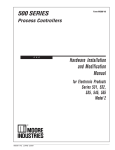
Figure 1. The TRZ Smart HART Temperature Transmitter’s remotely programmable input and combination analog/digital output make it the
perfect answer to problems encountered when interfacing control room equipment and field sensors.
TRZ Smart HART Temperature Transmitter
(HART Slave Device)
NOTE:
The HART Communicator or PC with Smart Hart
Interface Cable may be connected at any termination
point on the signal loop. The HART Communicator
and the TRZ Signal loop must have between 250
and 1100 load for proper communications
–
DCS
PLC
SCADA
Data Recorder
Indicator
4-20mA Analog with Digital HART
superimposed
+
+
–
Power
Supply
PC with HART Modem
(Secondary Master)
running Moore Industries’
TRZ Configuration Software
HART
Primary Master
or Non-HART
Communicating Device
HART Communicator
(Secondary Master)
The Interface Solution Experts
1
TRZ
Specifications
HART Address Range: 0-15
Specifications (Addresses 1-15 are for
digital communications only)
Transmission Speed:
1200 baud
Character Format:
1 Start Bit - 8 Data Bits 1 Odd Parity Bit - 1 Stop Bit
Performance Input Accuracy:
Refer to Table 1
Output Accuracy:
±0.1% of span (Total
accuracy combines input
accuracy, output accuracy,
and temperature effect; for
T/C inputs only, include
Reference Junction
Compensation in Total
Accuracy.)
Reference Junction
Compensation Accuracy:
±0.8°C
Stability: T/C and RTD
inputs 0.05°C for one year
Isolation:
500Vac input-to-output
Output Response:
1.0 second for output to go
from 10-90% in response to a
full step change on input
(2.0 second response time
for resistance measurements
over 2000Ω and RTD
measurements over 1000Ω)
Ripple:
Less than 0.06V peak-topeak, max, 60-120Hz
Maximum Input Protection:
±35Vdc
Performance Power Supply Effect:
(continued) 0.005% of span per 1V
Load Effect: Negligible
within power and load limits
Load Capability:
Load (KΩ) = (Vdc - 12)
23mA
Burnout Protection:
User-programmable; Upscale
from 20.00 to 23.00mA;
Downscale from 3.60 to
4.00mA
Output Current Limiting:
User-programmable; Input
Overrange from 20.00 to
23.00mA; Input Underrange
from 3.60 to 4.00mA
T/C Input Impedance:
40µΩ, nominal
RTD Excitation:
200µA, ±10%
RTD Lead Wire Resistance
Maximum: 10Ω per wire for
temperatures less than
600°C; 30Ω per wire for
temperatures greater than
600°C; 0.1°C per 10Ω per
wire maximum compensation
error
Damping:
User-set; 0-15 seconds
Resolution:
Input, 16-bit; Output, 12-bit
Intrinsic Supply Range:: 12-28Vdc
Safety Internal Inductance: ≤15µH
Intrinsic Internal Capacitance:
Safety ≤1nF
(continued) Barrier Data:
28Vdc, max; 100mA max
Ambient Operating and Storage
Conditions Range: –40°C to +85°C
(–40°F to +185°F)
Relative Humidity:
0-98%, condensing
Ambient Temperature
Effect: 0.01% of span per
°C change, max; 0.003% of
span per °C change, typical
Effect on Reference
(Cold) Junction
Compensation: ±0.005°C
per °C change from room
temperature (25°C)
RFI/EMI Immunity: 30V/m
@ 20-1000MHz, when
tested according to SAMA
standard 33.1 in metal
enclosure (10V/m @
27-1000MHz, when tested
according to IEC 1000-4-31995 in metal enclosure)
Common Mode Rejection:
110dB, min, @ 50/60Hz
Normal Mode Rejection:
55dB, typical, @ 1V peakto-peak, 50/60Hz
Weight In LH1 Housing:
329 g (11.6 oz)
In LH2 Housing:
549 g (19.4 oz)
In HPP Housing:
51 g (1.8 oz)
Specifications subject to change without notice. Printed in the U.S.A.
Complete Temperature Assemblies
We are your “One-Stop Temperature Shop”; with
ready-to-install assemblies that include your
choice of everything from TRY or TRX Non-HART
PC-Programmable transmitters, to isolators
(HART and non-HART), power supplies, and
meters.
We offer complete lines of RTDs, thermocouples,
thermowells, connection heads, and fittings—with
all types of certifications, colors, materials, and
specifications.
2
The Interface Solution Experts
TRZ
Table 1. Input Types and Accuracy Specifications for the TRZ Transmitter
Input
Type
α
Measuring
Range
200 to 850°C
328 to 1562°F
200 to 320°C
328 to 608°F
100 to 650°C
148 to 1202°F
100 to 320°C
148 to 608°F
200 to 500°C
328 to 932°F
200 to 320°C
328 to 608°F
Minimum
Span
Input
Accuracy
10°C
18°F
±0.2°C
±0.36°F
50 to 250°C
58 to 482°F
10°C
18°F
±0.2°C
±0.36°F
50 to 200°C
58 to 392°F
10°C
18°F
±0.2°C
±0.36°F
0 to 390Ω
5Ω
±0.08Ω
0 to 2200Ω
25Ω
±0.4Ω
Maximum
Range
210 to 1200°C
346 to 2192°F
250 to 1372°C
454 to 2502°F
270 to 1000°C
454 to 1832°F
250 to 400°C
454 to 752°F
Conformance
Range
200 to 1000°C
328 to 1832°F
230 to 1370°C
382 to 2498°F
250°C to 900°C
418 to 1652°F
220 to 400°C
364 to 752°F
Minimum
Span
Input
Accuracy
50 to 1768°C
58 to 3216°F
0 to 1750°C
32 to 3182°F
100°C
180°F
±2.0°C
±3.6°F
270 to 1300°C
454 to 2372°F
100 to 1820°C
392 to 3308°F
130 to 1300°C
202 to 2372°F
500 to 1820°C
932 to 3308°F
50°C
90°F
50°C
90°F
±1.0°C
±1.8°F
0 to 2300°C
32 to 4172°F
0 to 2300°C
32 to 4172°F
100°C
180°F
200 to 900°C
328 to 1652°F
200 to 600°C
328 to 1112°F
10 to +70mV
0.1 to +1.1V
200 to 900°C
328 to 1652°F
200 to 600°C
328 to 1112°F
50°C
90°F
±1.0°C
±1.8°F
n/a
2mV
20mV
±0.04mV
±0.4mV
0.003850
Platinum
0.003902
RTD
0.003916
Nickel
Ω
0.00618
25-500
1000
25-500
1000
25-500
1000
25-500
1000
Copper
0.00427
25-1000
Ω
Direct
Resistance or
Potentiometer
n/a
n/a
Input
Type
J
K
E
T
R
S
T/C
N
B
C (W5)
D (W3)
L
U
mV
DC
50°C
90°F
±1.0°C
±1.8°F
40°C
72°F
±2.0°C
±3.6°F
The Interface Solution Experts
3
TRZ
Ordering Information
Unit
TRZ
Smart
HART
Temperature
Transmitter
Input
PRG
Programmable
with standard
HART
Communicator,
HART-based
control system,
or Moore
Industries'
PC-based
Configuration
Software
(included)
Output
4-20MA
output with
HART digital
data
superimposed
Power
12-28Vdc
(loop-powered
from output
side)
Housing
HPP Hockey-puck housing for mounting in standard connection heads
LH1NS* Connection head (FM approved, NEMA 4X, IP66) with two
entry ports: ½-inch NPT cable and process—black PBT polyester
cover
LH1NA* Connection head (FM approved, NEMA 4X, IP66) with two
entry ports: ½-inch NPT cable and process—black aluminum cover
LH1MS* Connection head (FM approved, NEMA 4X, IP66) with two
entry ports: M20 cable and ½-inch NPT process—black PBT
polyester cover
LH1CS* Connection head with two entry ports: M20 cable and G½
(BSP) process—black PBT polyester cover
LH2NS*‡ Explosion-proof connection head (FM approved, Class I,
Div 1, Groups A**,B,C,D; Class II, Groups E,F,G; Class III) with two
entry ports: ½-inch NPT cable and process—black metal cover
LH2MS*‡ Explosion-proof connection head (FM approved, Class I,
Div 1, Groups A**,B,C,D; Class II, Groups E,F,G; Class III) with two
entry ports: M20 cable and ½-inch NPT process—black metal cover
CH6 Plastic polypropilene connection head
* For alternate cover color, replace the fifth designator in the LH1 model number with
appropriate letter from below (i.e. LH1NG): C = Clear (LH1 only), B = Blue, R = Red,
Y = Yellow, G = Green.
NOTE: Add "P" suffix to any LH or CH housing for 2-inch pipe mounting hardware (e.g.,
LH1NSP).
** For Group A (only) all conduit must be sealed within 18 inches.
‡ LH2 Explosion-proof certification carries 60°C (140°F) max ambient
temperature restriction.
Other connection heads, cabinets, and enclosures are also available.
Ask your Interface Solutions Expert for details.
When ordering specify: Unit / Input / Output / Power [Housing]
Model Number Example: TRZ / PRG / 4-20MA / 12-28DC [LH1NSP]
Model and Serial Numbers
Additional Parts
Moore Industries uses a system of model and serial
numbers to keep track of all of the information on
every unit it sells and services. If a problem occurs
with a TRZ, check for a tag affixed to the unit listing
these numbers. Supply the Customer Support representative with this information when calling.
Each TRZ order comes with one copy of our Configuration Software on a 3½-inch floppy disk (Windows
‘95, ‘98, and Windows NT compatible). A HART Communicator is not included with the TRZ. The TRZ unit
will work with any standard, third-party unit, such as
the Fisher-Rosemount model 275.
If additional units are needed, use the information
printed in bold text in the table above to “build” a
model number for the type of transmitter required.
Additional accessories are available as follows:
4
The Interface Solution Experts
Part Number
235-829-01
PC-Programming Kit
Includes one copy of the TRZ Intelligent PC
Configuration Software and one HART-to-RS232
Cable with HART Modem.
Part Number
235-75120-03
TRZ Intelligent PC Configuration Software
(One copy comes free with each order)
Part Number
803-048-26
HART-to-RS232 Smart Interface Cable
with HART Modem
TRZ
Configuring a TRZ
The TRZ can be configured with either a HART Communicator or a PC and Moore Industries’ TRZ Intelligent PC Configuration Software.
One of the benefits of the TRZ transmitter is that
there are no internal or external controls to adjust or
settings to change. All operating parameters are set
using either a HART Communicator or the Configuration software. Once these software settings are
made, they are “downloaded” to the transmitter in the
form of a Configuration File and stored in the nonvolatile unit memory and on your PC hard drive or
diskette. The transmitter communicates with the PC
through a HART modem connection to the PC’s
serial (COM) port. The transmitter and the HART
Communicator can communicate at any termination
point on the loop.
The following section of the manual contains instructions for configuring the TRZ with or without the use of
a HART Communicator:
• Installing the TRZ Configuration Software
(if necessary) page 8
• Saving the TRZ Configuration Files
(if necessary) page 10
• Setting Output, page 13, 17-18
• Configuring the Device Information,
page 13
• Using the Loop Test function, page 14
• Trimming the Input, page 14
• Displaying and Resetting the Minimum and
Maximum Process Values, page 15
You can configure the TRZ with either a standard
HART Communicator or our PC software. Figure 2
shows the hookup for configuring the TRZ with a PC.
Figure 3 shows the configuration hookup with a HART
Communicator. Refer to Table 2 for the specifications
for the equipment shown in these figures.
The Interface Solution Experts
5
TRZ
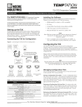
Figure 2. Using a PC to configure the TRZ.
LOAD=250 OHMS
+
–
OPTIONAL
CURRENT
METER
+
12-28Vdc
POWER
–
TRZ
+PS –PS
TEST
3
3-WIRE RTD
OR DECADE
RESISTANCE BOX
+ –
3
+ –
TRZ
+ –
3
TEST
HART MODEM
CONNECTS TO SERIAL
(COM) PORT
OF PC
2-WIRE RTD
OR DECADE
RESISTANCE BOX
3
2-WIRE
POTENTIOMETER
INPUT
4-WIRE RTD
OR DECADE
RESISTANCE BOX
3
+ –
+ –
3
+
3-WIRE
POTENTIOMETER
INPUT
–
THERMOCOUPLE
SIMULATOR
+ –
3
+
6
+ –
3
+ –
4-WIRE
POTENTIOMETER
INPUT
–
MILLIVOLT
INPUT
The Interface Solution Experts
THE PC CAN BE
CONNECTED AT
ANY POINT ON THE
OUTPUT SIDE OF
THE LOOP.
TOTAL LOOP
RESISTANCE MUST BE
BETWEEN 250 AND
1100 OHMS FOR GOOD
HART COMMUNICATIONS
TO OCCUR.
TRZ
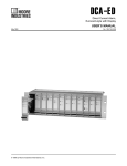
Figure 3. Using a HART Communicator to configure the TRZ.
LOAD=250 OHMS
+
–
OPTIONAL
CURRENT
METER
+
12-28Vdc
POWER
–
TRZ
+PS –PS
TEST
3
3
THE HART COMMUNICATOR
CAN BE CONNECTED AT ANY POINT
ON THE OUTPUT SIDE OF THE LOOP.
THE TOTAL LOOP RESISTANCE MUST BE
BETWEEN 250 AND 1100 OHMS FOR
GOOD HART COMMUNICATIONS TO
OCCUR.
+ –
TRZ
+ –
3-WIRE RTD
OR DECADE
RESISTANCE BOX
3
TEST
+ –
2-WIRE RTD
OR DECADE
RESISTANCE BOX
3
2-WIRE
POTENTIOMETER
INPUT
4-WIRE RTD
OR DECADE
RESISTANCE BOX
3
3
+ –
+ –
+
3-WIRE
POTENTIOMETER
INPUT
–
THERMOCOUPLE
SIMULATOR
3
+ –
+ –
+
3
+ –
4-WIRE
POTENTIOMETER
INPUT
–
MILLIVOLT
INPUT
The Interface Solution Experts
7
TRZ
Table 2. Assembling the equipment needed to configure the TRZ.
Device
Specifications
Variable Input Simulator for
Thermocouple, RTD, Millivolt,
Variable; Accurate to ±0.05% of unit span.
Potentiometer, or Decade
Resistance Box
Power Supply
Precision Load Resistor
Multimeter (optional)
32Vdc, ±10%
250Ω. ±0.01%
HART specifies that total loop resistance be maintained
between 250Ω and 1100Ω.
Accurate to ±0.025% of span; e.g., Fluke Model 87
80386-based IBM PC, or 100% compatible;
1.44Mb floppy diskette drive;
4Mb free Random Access Memory (RAM);
1Mb free disk space on hard drive (suggested);
Microsoft Windows® '95, '98, or NT
Personal Computer (optional)
(Windows® '98 or NT will require additional RAM and a
faster processor--see requirements on Windows® manual
for details)
1 (one) free serial communications port (COM 1, 2, or 3)
set to 4800 baud, no parity, 8 data bits, and 1 stop bit
HART Modem Cable
Moore Industries part number 803-048-26, or equivalent
(required if using a PC)
HART Communicator
Fisher-Rosemount Model 275 or equivalent
(required if not using a PC)
Moore Industries' TRZ
Configuration software, Version 1.0 or greater, successfully installed on the hard
TRZ_setup.exe disk of the specified PC
(required if using a PC)
If using a PC...
It will be necessary to install Moore Industries’ TRZ
Intelligent PC Configuration software first. Once the
program is loaded and running, nearly all of the
operating parameters for the connected transmitter
are shown on a single screen (see Figure 4). This
makes it easy to determine which aspects of
transmitter operation need to be changed to suit the
application requirements.
Installing the TRZ Configuration Software
Refer to Table 2 for the specifications of the PC
needed.
8
1.
Insert the diskette labeled “TRZ Installation”
into the floppy drive of the PC.
2.
Quit any applications that may be running in
the background on the PC, including any virus
detection software or other programs running in
Terminate and Stay Resident (TSR) mode.
The Interface Solution Experts
3.
In Windows 95, go to the “Start” menu, and
access “Settings”, then “Control Panels”, and
finally “Add/Remove Programs”.
4.
Click on “Install” and then follow the on-screen
instructions.
Once the Configuration Program is installed on the
PC, the TRZ can be connected to equipment to
simulate input and monitor output. With the PC
program, the user can then view and/or change its
operating parameters.
If not using a PC...
Use the HART Communicator to specify the operating
parameters of the TRZ.
TRZ
Figure 4. Most of the TRZ Operating Parameters can be set from the Main Screen of the Configuration Program.
No Transmitter Needed
It is not necessary to connect the TRZ to a PC to
create Configuration Files using the Configuration
Software. The Configuration Program can be run
without connecting a transmitter, and most operating
parameters can be set without benefit of input from a
sensor or from a transmitter. This makes it easy to
create a set of operating parameters, save them to
disk, and download them to one or more transmitters
at a later time.
Note:
Not all parameters can be set
without a transmitter attached.
The TRZ must be connected to the PC in order to:
• Trim Input
• Trim Output
• Assign a Tag
• Perform a Loop Test
• Receive (via download) a Configuration File
And, perhaps most importantly...
• SAVE THE CONFIGURATION FILE ALREADY IN
THE TRANSMITTER’S MEMORY (refer to
“Saving the TRZ Configuration Files”, which
follows.)
The Interface Solution Experts
9
TRZ
Figure 5. Using the “Save As...” Function to Store the TRZ Default Settings on Disk.
Later, if you want to retrieve the saved information,
you can do so by selecting “Open” from the “File”
menu or by pressing the “
” icon and then using
standard Windows’ conventions to find the file.
Using the PC Program
Once the default configuration has been saved to
disk, it is safe to program the other TRZ parameters.
Use either the PC-based Configuration software or the
HART Communicator–the results are the same.
For help with the PC program, press F1.
Consult the documentation for the HART Communicator for information on getting help with the hand-held’s
menus.
Using the HART Communicator
Saving the TRZ Configuration Files
Every TRZ is shipped from the factory with a
Configuration File already installed in its memory.
This file is comprised of either the factory default set
of operating parameters or the set of parameters
specified by the customer at the time of order.
The Factory Defaults are...
• Input Type: 3-Wire Platinum RTD, 100Ω, α0.3850
• Input Range: 0 to 100°C (32 to 212°F)
• Output: 4-20mA with HART
• Upscale Drive (to 23mA) on input failure
• Overrange Maximum Value: 22.0mA
• No input damping
To save the Configuration File already resident in the
transmitter’s memory, pull down the “File” menu on
the Main Configuration Screen (Figure 5) and select
“Save As...”.
Use standard Windows’ conventions to save the file
on the PC disk in the desired location.
Alternatively, click on the “
” icon at the top of the
screen. This starts the “Save As...” function in the
same manner.
10
The Interface Solution Experts
The TRZ is programmed using a HART Communicator. If your communicator is equipped with a Device
Description (DD) for the TRZ, the following section,
“Programming the TRZ when a Device Description is
Available”, gives an overview of the menus and
instructions for programming. To determine if your
communicator has the TRZ Device Description,
press “1” to select “Offline” and press “1” again to
select “New Configuration”. A list of companies will
appear which, if your communicator is loaded with
the TRZ Device Description, will include Moore
Industries.
If your communicator is not equipped with the TRZ
Device Description, go to “Programming the TRZ
when a Device Description is not available” on page
17. Some TRZ capabilities can only be accessed if
your communicator is equipped with a Device
Description. Moore Industries can factory-configure
TRZ parameters that are not accessible through the
generic DD.
Moore Industries can update your HART Communicator with all of the latest, approved HART Device
Descriptions, including the DD for the TRZ. Just
send your communicator to our Interface Solution
Center headquarters in Sepulveda, California with
our configuration sheet indicating the DD’s you need.
We'll load the Device Descriptions of your choice for
a nominal charge.
TRZ
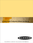
Figure 6. Summarizing the TRZ Configuration Menus in a HART Communicator
MAIN MENU
1 DEVICE SETUP
DEVICE SETUP
INPUT SETUP
1 INPUT SETUP
1 SIGNAL CONDITION
2 SENSOR TYPE
3 LRV
4 URV
2 TEMP
5 DAMP
6 UNIT
7 WIRE NO.
3 LRV
2 OUTPUT SETUP
OUTPUT SETUP
1 UNDER LIM
2 OVER LIM
3 SENSOR ERROR
4 URV
3 DEVICE INFORMATION
DEVICE INFORMATION
1 DISTRIBUTOR
2 MODEL
3 DEV ID
4 TAG
5 I OUT
5 DATE
6 WRITE PROTECT NONE
Key
% RANGE = Output Current in % of Span
# PREAMBLES = Number of Preamble Characters
DAMP = Damping Value
DEV ID = Device Identification
DIAG = Diagnostic
I OUT = Output Current
LRV = Lower Range Value
MAX VALUE = Maximum Process Value
MIN VALUE = Minimum Process Value
OFFS = Offset
POLL ADDR = Polling Address
URV = Upper Range Value
WIRE NO = Number of Input Wires
7 DESCRIPTOR
8 MESSAGE
6 % RANGE
9 FINAL ASMBLY NUM
REVISION #S
HART OUTPUT
HART OUTPUT
1 POLL ADDR
4 DIAG/SERVICE
DIAG/SERVICE
2 # PREAMBLES
1 LOOP TEST
7 DATA LOGGER
DATA LOGGER
2 D/A TRIM
1 MAX PROCESS VALUE
2 MIN PROCESS VALUE
3 RESET MIN/MAX
3 SENSOR TRIM
SENSOR TRIM
1 FACTORY TRIM
2 ONE POINT TRIM
3 TWO POINT TRIM
4 TEMP
5 S. OFF
6 S.GAIN
The Interface Solution Experts
11
TRZ
Alternatively, the TRZ Device Description is available from any service center that is approved to upgrade universal HART communicators. Consult the
Interface Solution Center nearest you for locations.
Programming the TRZ when a
Device Description is Available
With the TRZ connected as shown in either Figure 2
or 3, apply power and turn the communicator on.
After a brief self-test, the communicator will show
the main menu and identify the unit as a TRZ.
To configure the TRZ input:
1.
Highlight DEVICE SETUP in the Main menu
and push the right arrow.
2.
Highlight INPUT SETUP and push the right
arrow.
3.
Highlight SIGNAL CONDITION and push the
right arrow to show the current settings for
sensor type, upper and lower sensor values,
and the minimum span. Use the left arrow to
return to the Input Setup menu.
4.
Highlight SENSOR TYPE and push the right
arrow to select the sensor type and
parameters. Enter the input type and
parameters and push ENTER to return to the
Input Setup menu.
This section contains the instructions for
programming the TRZ using a HART Communicator
that has been programmed with a TRZ HART Device
Description (see page 11). If your communicator
doesn’t have a TRZ Device Description, skip to
“Programming the TRZ when a Device Description is
NOT Available” on page 15.
Note:
After the sensor type and parameters are
selected, the TRZ defaults to the range
listed in Table 1. If you wish to modify
the range, see steps 5 and 6. Otherwise,
skip to step 7.
Figure 6 on page 11 shows an overview of the
programming menus for the configuration process.
This figure will be used frequently.
5.
Highlight LRV and push the right arrow to
change the lower range value. Input the new
value and push ENTER to return to the Input
Setup menu.
6.
Highlight URV and push the right arrow to
change the upper range value. Input the new
value and push ENTER to return to the Input
Setup menu.
7.
Highlight DAMP and push the right arrow to
enter a damping time between 0 and 15
seconds. Input the value and push ENTER to
return to the Input Setup menu.
8.
Highlight WIRE NO. and push the right arrow to
enter the number of wires used to connect the
TRZ to the input. Input the number and push
ENTER to return to the Input Setup menu.
9.
Highlight CABLE R and push the right arrow to
enter the amount of resistance present in the
wire. Input the value and push ENTER to
return to the Input Setup menu.
Displaying the Current Process Value
The Main Menu displays the current process value
(i.e. °C in a temperature application), the lower and
upper range values, the actual output current, and the
output current as a percentage of output span.
Configuring the TRZ’s Input
In the “Input Setup” Menu, you can program the type
of sensor being used, the sensor’s upper and lower
range values, a damping time between 0 and 15
seconds, the number of input wires, and the amount
of resistance in the wires connecting the TRZ to the
input.
Damping smooths input fluctuations by taking an
average over a user-programmed time period, and
using this value for the TRZ output. The damping
time can be set between 0 and 15 seconds.
10. Push HOME to return to the Main Menu.
12
The Interface Solution Experts
TRZ
Configuring the TRZ’s Analog Output
4.
In the “Output Setup” menu, you can enter the output
for measurements outside of the programmed range
and for sensor failure. The output can go upscale
(from 20.00 to 23.00mA) or downscale (from 3.60 to
4.00mA).
To configure TRZ analog output:
1.
Highlight DEVICE SETUP in the Main
Menu and push the right arrow.
2.
Highlight OUTPUT SETUP and push the
right arrow.
3.
Displayed next to UNDER LIM is its
current setting. Highlight UNDER LIM and
push the right arrow to enter the output
current for measurements lower than the
programmed range. Input the value and
push ENTER.
4.
5.
6.
Displayed next to OVER LIM is its current
setting. Highlight OVER LIM and push the
right arrow to enter the output current for
measurements higher than the
programmed range. Input the value and
push ENTER.
Displayed next to SENSOR ERROR is its
current setting. Highlight SENSOR
ERROR and push the right arrow to enter
the output current in the event of sensor
failure. Input the value and push ENTER.
Push HOME to return to the Main Menu.
Note:
If the polling address is set to 0, the TRZ
is automatically set to analog mode.
Multiple TRZ’s on the same bus must have
different addresses.
5.
Displayed next to # REQ PREAMBLES is 5.
This is the number of preamble characters sent
by the master to the slave. This cannot be
changed.
6.
Push HOME to return to the Main Menu.
Configuring the Device Information
In the “Device Information” menu, you can enter a tag
(8 characters), date, descriptor (i.e. a location code of
up to 16 characters), a message (32 characters), and
final assembly numbers for the TRZ.
To configure the device information:
1.
Highlight DEVICE SETUP from the Main Menu
and press the right arrow.
2.
Highlight DEVICE INFORMATION and press
the right arrow.
3.
Scroll past the displays of DISTRIBUTOR,
MODEL, and DEV ID. They cannot be
changed in the field.
4.
Highlight TAG and press the right arrow to
enter an eight character name for the unit.
Input the name and press ENTER to return to
the Device Information menu.
5.
Displayed next to DATE is the date input into
the TRZ. Highlight DATE and press the right
arrow to enter a date for the unit. Input the
date and press ENTER to return to the Device
Information menu.
6.
Scroll past WRITE PROTECT NONE This
cannot be changed in the field.
Configuring the TRZ’s HART Output
In the “HART Output” menu, you can enter a polling
address between 0 and 15 for an individual TRZ and
display the number of preamble characters sent by
the master to the slave to ensure synchronization.
To configure the HART output:
1.
Highlight DEVICE SETUP in the Main Menu
and push the right arrow.
2.
Highlight DEVICE INFORMATION and push
the right arrow.
3.
Scroll to HART OUTPUT and push the right
arrow.
Displayed next to POLL ADDR is the current
address. Highlight POLL ADDR and push the
right arrow to enter the polling address for the
module. It can be any integer between 0 and
15. Input the address and push ENTER to
return to the HART screen.
The Interface Solution Experts
13
TRZ
7.
Highlight DESCRIPTOR and press the right
arrow to enter a location code of up to 16
characters. Input the code and press ENTER
to return to the Device Information menu.
8.
Highlight MESSAGE and press the right arrow
to enter a message of up to 32 characters.
Input the message and press ENTER to return
to the Device Information menu.
9.
Highlight FINAL ASSEMBLY # and press the
right arrow to enter a reference number of up to
8 characters. Input the number and press
ENTER to return to the Device Information
menu.
10. Highlight REVISION #S and press the right
arrow to display the revision number of the
command set, the TRZ, and the Device
Description software. These cannot be
changed.
11. HART OUTPUT configures the HART
OUTPUT. See page 13 for instructions.
12. Push HOME to return to the Main Menu.
6.
Highlight “End” and press “Enter”. Push OK to
return the loop to automatic control. The
screen returns to the Diag/Service menu.
7.
Push HOME to return to the Main Menu.
Trimming the Input Sensor
From the “Sensor Trim” menu, you can enter the
offset for a non-calibrated sensor or reset the TRZ to
the factory settings.
Offset for non-calibrated sensors can be entered two
different ways. The first time a non-calibrated sensor
is connected, SENSOR TRIM is used to enter the
offset because it allows the TRZ to synchronize with
the input. Subsequent adjustments to the offset can
be accomplished in SENSOR TRIM or in OFFS.
SENSOR TRIM can only be used in a controlled
environment because fluctuating input makes it difficult for the TRZ to synchronize with the input. OFFS
can be used in a controlled environment or in the
field.
To trim the sensor:
Changing Loop Current to a Fixed Value
The “Diag/Service” menu allows you to change the
loop current to a fixed output. Once the TRZ’s output
current is set to a known value, it can be checked
against the value being received and displayed by
your receiving device.
1.
Highlight DEVICE SETUP in the Main Menu
and push the right arrow.
2.
Highlight DIAG/SERVICE and push the right
arrow.
3.
Highlight SENSOR TRIM and push the right
arrow to start the trim process.
Note:
To change the offset without
synchronizing to the input, skip to step 8.
To change the loop current to a fixed value:
1.
Highlight DEVICE SETUP in the Main Menu
and push the right arrow.
2.
Highlight DIAG/SERVICE and push the right
arrow.
3.
Highlight LOOP TEST and push the right arrow
to change the loop current to a fixed output.
Note:
The TRZ has to be removed from
automatic control in order to run the Loop
Test.
14
4.
Push OK after removing the loop from
automatic control.
5.
Choose the current output value and push
ENTER. Push OK if the entry is correct, abort
if it is not.
The Interface Solution Experts
To reset the TRZ to the factory settings,
go to step 9.
Before beginning Sensor Trim, the TRZ
reverts to the factory trim settings. This
takes 5 seconds. Pushing Abort during
this time stops the process.
5.
After reverting to the factory settings, the TRZ
will synchronize with the input. Adjust the input
until the desired value appears, then press OK.
6.
A space appears below the input value. Input
the desired offset value into the space and
press ENTER to return to the Sensor Trim
menu.
TRZ
7.
Highlight TEMP and push the right arrow to
display the temperature. Press ENTER to
return to the Sensor Trim menu.
8.
Highlight OFFS and push the right arrow to
change the offset. Input the desired offset and
push ENTER to return to the Sensor Trim
menu.
9.
Highlight FACTORY TRIM and push the right
arrow to reset the TRZ to the factory settings.
If you do not want to reset the TRZ, skip to step
10.
Note:
Once the factory trim process is
complete, all other trim values are
erased.
Reset takes 5 seconds. Pushing Abort
during this time stops the process.
10. Push HOME to return to the Main Menu.
To display the minimum and maximum values:
1.
Highlight DATA LOGGER in the Main Menu
and push the right arrow.
2.
Next to MAX VALUE is the highest process
value since the last reset. Push EXIT to return
to the Data Logger menu.
3.
Next to MIN VALUE is the lowest process value
since the last reset. Push EXIT to return to the
Data Logger menu.
4.
Push HOME to return to the Main Menu.
Resetting the Minimum and Maximum
Process Values
The minimum and maximum process values can be
reset in this menu. Once reset, they are irretrievable.
Resetting the minimum and maximum process values:
1.
Highlight DATA LOGGER in the Main Menu
and push the right arrow.
2.
Highlight RESET MIN/MAX and push the right
arrow to reset the maximum and minimum
process values.
Displaying the Minimum and Maximum
Process Values
The highest and lowest process values since the last
reset are displayed in the “Data Logger” menu. These
values are held in volatile memory and are irretrievable if the TRZ loses power or is reset.
Note:
Reset takes five seconds. Pushing Abort
during this time stops the process.
3.
Push HOME to return to the Main Menu.
The Interface Solution Experts
15
TRZ
Figure 7. Generic Menu Overview
ONLINE GENERIC
DEVICE SETUP
PROCESS VARIABLE
1 DEVICE SETUP
1 PROCESS VARIABLES
1 SNSR
2 AI %
2 PV
3 A01 DISPLAY
3 PV AO
4 PV LRV
2 DIAG/SERVICE
DIAG/SERVICE
1 TEST DEVICE
5 URV
2 LOOP TEST
3 BASIC SETUP
3 CALIBRATION
CALIBRATION
4 D/A TRIM
1 APPLY VALUES
BASIC SETUP
2 ENTER VALUES
ENTER VALUES
1 TAG
1 PVLRV
2 PV UNIT
2 URV
3 RANGE VALUES
RANGE VALUES
3 PVUSL
1 PVLRV
4 PVLSL
2 URV
3 PVLSL
4 USL
4 DEVICE INFORMATION
5 PVXFER FNCTN
6 PV DAMP
DEVICE INFORMATION
1 DISTRIBUTOR
2 MODEL
3 DEV ID
4 TAG
4 DETAILED SETUP
DETAILED SETUP
5 REVIEW
1 SENSORS
5 DATE
SENSORS
1 PV
2 PV SNSR
Key
AI % = % of Analog Input
AO = Analog Output
DAMP = Damping Value
DEV ID = Device Identification
DIAG = Diagnostic
D/A TRIM = Trim Digital/Analog
LRV = Lower Range Value
LSL = Lower Sensor Level
NUM REG PREAMS = Number of Preamble Characters
POLL ADDR = Polling Address
PV = Process Variable
SNSR = Sensor
URV = Upper Range Value
USL = Upper Sensor Level
XFER FNCTN = Transfer Function
3 SENSOR INFORMATION
2 SIGNAL CONDITION
SIGNAL CONDITION
1 SNSR DAMP
2 URV
3 AI LRV
4 AI XFER FNCTN
5 AI % RANGE
ANALOG OUTPUT
3 OUTPUT CONDITION
OUTPUT CONDITION
1 ANALOG OUTPUT
4 DEVICE INFORMATION
1 AO1
2 AO ALRM TRIP
3 LOOP TEST
4 D/A TRIM
5 SCALED D/A TRIM
2 HART OUTPUT
HART OUTPUT
1 POLL ADDR
2 NUM REG PREAMS
3 BURST MODE
4 BURST OPTION
16
The Interface Solution Experts
TRZ
Programming the TRZ when a
Device Description is NOT
Available
This section contains the instructions for programming a TRZ using a HART communicator without a
TRZ Device Description. If your communicator has
a Device Description for the TRZ, please see “Programming the TRZ when a Device Description is
Available” on page 12.
Displaying the Current Process Values
The initial screen, the “Online Generic” menu,
displays the process value, analog output, and the
programmed upper and lower parameters of the
process value. The main overview menu (Figure 7
on page 16) shows the screen. This menu will be
used throughout the process of programming a TRZ
without a HART device description.
Configuring TRZ Input
The “Basic Setup” menu allows you to enter a name
for an individual TRZ, the units of measurement, the
upper and lower range and sensor values, and a
damping time between 0 and 15 seconds.
Damping smooths input fluctuations by taking an average over a user-programmed time period and using
this value for the TRZ output.
To configure the TRZ input:
1. Highlight DEVICE SETUP in the Online
Generic menu and push the right arrow.
2. Highlight BASIC SETUP and push the right
arrow.
3. Highlight TAG and push the right arrow to
display the current name of an individual
TRZ. Push EXIT to return to the Basic Setup
menu. To change or enter the TAG, skip to
step 6.
4. Highlight PV UNIT and push the right arrow
to enter the measurement units. Scroll to the
correct units and push ENTER. The screen
returns to the Basic Setup menu.
5. Highlight Range Values and push the right
arrow to enter the upper and lower range and
sensor values for the unit.
A.
Highlight PVLRV to enter the Lower Range
Value for the Process Variable. Input the
value and then push ENTER to return to the
Range Values Menu.
B.
Highlight URV to enter the Upper Range
Value for the Process Variable. Input the
value and then push ENTER to return to the
Range Values menu.
C. Highlight PVLSL to enter the Lower Sensor
Level for the Process Variable. Input the
value and then push ENTER to return to the
Range Values menu.
D. Highlight USL to enter the Upper Sensor
Level for the Process Variable. Input the
value and then push ENTER to return to the
Range Values menu.
E.
Scroll to PVLRV and use the left arrow to
return to the Basic Setup menu.
6. Highlight DEVICE INFORMATION and push
the right arrow to enter the name and date for
the TRZ.
A.
Scroll past DISTRIBUTOR, MODEL, and
DEV ID. They cannot be changed.
B.
Highlight TAG and push the right arrow to
enter a name up to 8 characters long for the
TRZ. Input the name and push ENTER to
return to the Device Information menu.
C. Highlight DATE and push the right arrow to
enter the date. Input the date and push
ENTER to return to the Device Information
menu.
D. Scroll to DISTRIBUTOR and push the left
arrow to return to the Basic Setup menu.
7. PV XFER FNCTN is not used. Highlight PV
DAMP and push the right arrow to enter a
damping time between 0 and 15 seconds for
the process value. After entering the value,
push ENTER to return to the Basic Setup
menu.
8. Press HOME to return to the Online Generic
menu.
Configuring TRZ Analog Output
The “Analog Output” menu displays the analog output, changes the loop current to a fixed value so that
it can be checked against the value being received
and displayed by your receiving device, and enters
and trims the sensor.
The Interface Solution Experts
17
TRZ
10. The screen will display the measured
temperature. Input this temperature and
push ENTER to return to the Analog Output
menu.
To configure the analog output:
1. Highlight DEVICE SETUP from the Online
Generic menu and push the right arrow.
2. Highlight DETAILED SETUP and push the
right arrow.
3. Highlight OUTPUT CONDITION and push the
right arrow.
4. Highlight ANALOG OUTPUT and push the
right arrow.
5. Highlight AO1 and push the right arrow to
view the analog output.
11. Highlight SCALED D/A TRIM and push the
right arrow to enter the offset. Input the
offset and push ENTER to return to the
Analog Output menu.
12. Press HOME to return to the Online Generic
menu.
Configuring HART Output
6. AO ALRM TRIP is not used. Scroll to LOOP
TEST and push the right arrow to change the
output current to a fixed value.
Note:
The TRZ must be removed from
automatic control to run the loop test.
From the “HART Output” menu, you can enter the
polling address and display the number of preamble
characters sent by the master to the slave to ensure
synchronization.
To configure the HART Output:
1. Highlight DEVICE SETUP in the Online
Generic menu and push the right arrow.
7. Push OK to remove the loop from automatic
control and begin the loop test.
2. Highlight DETAILED SETUP and push the
right arrow.
8. Select the fixed current output value and
push ENTER. Highlight END to return to the
Analog Output menu.
3. Highlight OUTPUT CONDITION and push
the right arrow.
4. Highlight HART OUTPUT and push the right
arrow.
9. Highlight D/A TRIM and push the right arrow
to start the trim process.
Figure 8. Connecting the TRZ in Multi-Drop Configuration
HART-Based
DCS
(Primary
Master)
–
–
–
+
+
+
TRZ
(HART
Slave)
18
TRZ
(HART
Slave)
The Interface Solution Experts
TRZ
(HART
Slave)
HART
Communicator
(HART
Secondary
Master)
TRZ
5. Highlight POLL ADDR and push the right
arrow to enter the polling address for the
module. It can be any integer between 0 and
15. Input the address and push enter to
return to the HART output menu.
Note:
If the polling address is set to 0, the TRZ
is automatically set to analog mode.
Multiple TRZ’s on the same bus must have
different addresses.
6. Highlight NUM REG PREAMS and push the
right arrow to display 5. This is the number
of preamble characters sent from the master
to the slave during communication. This
cannot be changed. Push EXIT to return to
the HART Output menu.
7. BURST MODE and BURST OPTION are not
available on the TRZ.
8. Press HOME to return to the Online Generic
menu.
In multi-drop networks, the TRZ’s receiving device is
normally a HART-communicating control system
acting as the HART Primary Master. The control
system uses each TRZ’s individual address to
access real-time process data, sensor diagnostics,
and TRZ diagnostic data. The address is also used
to locate the appropriate TRZ to initiate configuration
and calibration. A HART communicator, acting as
the HART Secondary Master, can be used to simultaneously access information from, or transmit
configuration information to the TRZ from anywhere
along the HART digital link.
Make sure that the total loop resistance is at least
250Ω so that the 4-20mA signal containing the HART
protocol is not shorted. If loop resistance is less
than 250Ω, add a resistor.
Recommended Ground Wiring Practices
Moore Industries recommends the following ground
wiring practices:
• Any Moore Industries product in a metal case or
housing should be grounded.
• The protective earth conductor must be
connected to a system safety earth ground before
making any other connections.
Installation
Installation consists of physically mounting the unit
and completing the electrical connections.
• All input signals to, and output signals from,
Moore Industries’ products should be wired using
a shielded, twisted pair technique. Shields are to
be connected to an earth or safety ground at the
unit itself.
• The maximum length of unshielded input
and/or output signal wiring should be
two inches.
Mounting the TRZ
The TRZ fits inside a 30-35mm connection head (such
as the LH1) using captive mounting screws.
Making the Electrical Connections
The connections for the various TRZ inputs are shown
in Figures 2 and 3 on pages 6 and 7. The figures
show a single TRZ unit. If you are using multiple
units, connect them using the connections shown in
Figure 8.
CE Conformity
Installation of any Moore Industries’ products that
carry the CE certification (Commission Electrotechnique) must adhere to the guidelines above in order
to meet the requirements set forth in applicable EMC
(Electromagnetic Compatibility) directives (EN55011,
EN 50082-1, EN50082-2, etc.) Consult the factory for
the most current information on products that have
been CE certified.
The Interface Solution Experts
19
TRZ
Operation
Once programmed, calibrated, installed, and supplied
with the correct power, TRZ transmitters begin to operate immediately. Depending upon environmental
conditions, they can be expected to operate unattended for extended periods of time.
Communication Speed and Format
The speed of the HART transmission is 1200 baud.
The time delay between a master initiating a request
for data from a slave and the slave receiving and acknowledging the request depends upon which command is issued. Generally, a master can poll a slave
2-3 times per second.
The byte structure of the HART signal is:
HART Protocol
This section of the manual gives an overview of the
HART format used by TRZ modules during operation.
Use the information in this section to process the data
provided by the module(s) during operation. For more
information on the HART protocol, contact the HART
Foundation at:
The HART Communication Foundation
9390 Research Blvd, Suite 1-350
Austin, TX 78759-6540 U.S.A.
(512) 794-0369
www.ccsi.com/hart
Device Types
To implement two-way communication between the
TRZ and the device being used to configure it or receive its information, the TRZ operates in a HART
Master/Slave structure. The TRZ is the Slave (or
slaves in a multidrop network).
There can be two Masters per system: a Primary
Master and a Secondary Master. Masters are typically either a HART Hand-Held Communicator or a
HART-based control system.
In many applications, the Primary Master is a HART
Hand-Held Communicator. The communicator is
used solely as a configuration tool to set up the TRZ,
periodically view its real-time process measurement,
or view its operating and diagnostic information from a
loop termination point.
Digital Signal
One of the advantages of the HART protocol is that
the digital information is conveyed by the same wires
used to output the 4-20mA signal. After being polled
by the master, the TRZ responds to the inquiry by
modulating the 4-20mA current 0.5 mA above or below the output signal. 1200 Hz represents 1 and
2200 Hz represents 0.
20
The Interface Solution Experts
1 Start Bit, 8 Data Bits, 1 Odd Parity Bit, 1 Stop Bit.
Maintenance
Moore Industries suggests a quick check for terminal
tightness and general unit condition every 6-8 months.
Always adhere to any site requirements for programmed maintenance.
Customer Support
Moore Industries is recognized as the industry leader
in delivering top quality to its customers in products
and services. We perform a battery of stringent quality assurance checks on every unit we ship. If any
Moore Industries product fails to perform up to rated
specifications, call us for help. Our highly skilled staff
of trained technicians and engineers pride themselves
on their ability to provide timely, accurate, and practical answers to your process instrumentation questions.
Factory phone numbers are listed on the back cover
of this manual.
If problems involve a particular TRZ, there are several
pieces of information that can be gathered before
you call the factory that will help our staff get the answers you need in the shortest time possible. For
the fastest service, gather the complete model and
serial number(s) of the problem unit(s) and the job
number of the original sale.
GUIDELINES AND CERTIFICATIONS
Low Voltage Directive
When installing any Moore Industries product,
always follow all local regulations and standards for
grounding, shielding, and safety. The following
grounding and wiring practices must be followed in
order for the unit(s) to meet the requirements set
fourth in the EMC directives EN50082-2 and
EN55011.
Grounding
If the unit has a metal case it is to be grounded.
(DIN rail mounted units should be mounted on a
grounded rail).
Wiring
Twisted shielded wire should be used for all input
and output signals. The shields are to be grounded
at the units, to earth ground (safety ground). The
unshielded part of the in/output wires should be no
longer than 2 inches.
CE Certification-related Guidelines
The following guidelines must be followed in order to
comply with EN61010-1 (Low Voltage Directive).
These items affect the AC version of the TRZ. If
these products are to be used in a non-CE
environment, this directive may be disregarded.
WARNING:
If this unit is used in a manner not specified by
Moore Industries, the protection provided by the
equipment may be impaired.
Switches and Circuit Breakers
A switch or circuit breaker must be wired in series
with the AC power conductors. The switch or circuit
breaker used must be located within three meters of
the unit.
WARNING:
Terminals on this unit may be connected to
hazardous voltages. Before making ANY
connections to this unit, ALL hazardous voltages
must be de-energized.
The circuit breaker or switch will only remove
power to the unit, hazardous voltages may still be
connected to other terminals on the unit.
Installation Category
All of Moore Industries’ terminals are rated CAT II,
except those with the -RF option. These terminals
are rated CAT I.
Equipment Ratings
The TRZ does not generate hazardous voltages,
rather, it accommodates a temperature input, and
generates a 4-20mA current output. Products
connected to the TRZ should be designed to receive
these inputs.
Supply Wiring
All power connections should be made with proper
wire.
The end of each conductor should be stripped no
more than 8mm. The end of the stripped wire
should be tinned with solder, or inserted into a
ferrule and crimped before being placed into a
terminal block.
Conductors connected to screw-type connections
should have a ring-lug or spade-lug crimped onto
the wire end.
EC Declaration of Conformity
Moore Industries-International, Inc.
16650 Schoenborn Street
North Hills, CA 91343-6196 U.S.A.
Date Issued: 30 Oct. 2013
No. 100-100-247 Rev. A
Page 1 of 1
Equipment Description:
Smart HART Temperature Transmitter
Model TRZ / PRG / 4-20MA / 12-28DC / *
* Indicates any housing as stated in the product data sheet.
Directive:
2004/108/EC (EMC)
Specifications Conformed To:
EN 61326-1:2006 Electrical equipment for measurement, control and laboratory use - EMC requirements
Equipment Description:
Smart HART Temperature Transmitter
Model TRZ / PRG / 4-20MA / 12-28DC / *
* Indicates any housing as stated in the product data sheet.
Directive:
94/9/EC (ATEX)
Provisions of the Directive Fulfilled by the Equipment:
Group II Category 1G EEx ia IIC T5-T6
Notified Body for EC-Type Examination:
UL International Demko A/S [Notified Body Number 0539]
Lyskaer 8, P.O. Box 514
DK-2730 Herlev, Denmark
EC-Type Examination Certificate:
DEMKO 03ATEX134605X
Technical Standards Referenced:
EN 50014:1997 + Amds 1 & 2 Electrical apparatus for potentially explosive atmospheres. General requirements.
EN 50020:2002 Electrical apparatus for potentially explosive atmospheres. Intrinsic safety ”i”.
EN 50284:1999 Special requirements for construction, test and marking of electrical apparatus of equipment group II,
category 1 G
Notified Body for Quality Assurance:
SIRA [Notified Body Number 0518]
Rake Lane, Eccleston,
Chester, Cheshire,
CH4 9JN, England
On Behalf of Moore Industries-International, Inc., I declare that, on the date the equipment accompanied by this
declaration is placed on the market, the equipment conforms with all technical and regulatory requirements of
the above listed directives.
Signature:
Deanna Esterwold, Quality Manager
RETURN PROCEDURES
To return equipment to Moore Industries for repair, follow these four steps:
1. Call Moore Industries and request a Returned Material Authorization (RMA) number.
Warranty Repair –
If you are unsure if your unit is still under warranty, we can use the unit’s serial number
to verify the warranty status for you over the phone. Be sure to include the RMA
number on all documentation.
Non-Warranty Repair –
If your unit is out of warranty, be prepared to give us a Purchase Order number when
you call. In most cases, we will be able to quote you the repair costs at that time.
The repair price you are quoted will be a “Not To Exceed” price, which means that the
actual repair costs may be less than the quote. Be sure to include the RMA number on
all documentation.
2. Provide us with the following documentation:
a) A note listing the symptoms that indicate the unit needs repair
b) Complete shipping information for return of the equipment after repair
c) The name and phone number of the person to contact if questions arise at the factory
3. Use sufficient packing material and carefully pack the equipment in a sturdy shipping
container.
4. Ship the equipment to the Moore Industries location nearest you.
The returned equipment will be inspected and tested at the factory. A Moore Industries
representative will contact the person designated on your documentation if more information is
needed. The repaired equipment, or its replacement, will be returned to you in accordance with
the shipping instructions furnished in your documentation.
WARRANTY DISCLAIMER
THE COMPANY MAKES NO EXPRESS, IMPLIED OR STATUTORY WARRANTIES (INCLUDING ANY WARRANTY OF MERCHANTABILITY OR OF FITNESS
FOR A PARTICULAR PURPOSE) WITH RESPECT TO ANY GOODS OR SERVICES SOLD BY THE COMPANY. THE COMPANY DISCLAIMS ALL WARRANTIES ARISING FROM ANY COURSE OF DEALING OR TRADE USAGE, AND
ANY BUYER OF GOODS OR SERVICES FROM THE COMPANY ACKNOWLEDGES THAT THERE ARE NO WARRANTIES IMPLIED BY CUSTOM OR
USAGE IN THE TRADE OF THE BUYER AND OF THE COMPANY, AND THAT
ANY PRIOR DEALINGS OF THE BUYER WITH THE COMPANY DO NOT IMPLY THAT THE COMPANY WARRANTS THE GOODS OR SERVICES IN ANY
WAY.
ANY BUYER OF GOODS OR SERVICES FROM THE COMPANY AGREES
WITH THE COMPANY THAT THE SOLE AND EXCLUSIVE REMEDIES FOR
BREACH OF ANY WARRANTY CONCERNING THE GOODS OR SERVICES
SHALL BE FOR THE COMPANY, AT ITS OPTION, TO REPAIR OR REPLACE
THE GOODS OR SERVICES OR REFUND THE PURCHASE PRICE. THE
COMPANY SHALL IN NO EVENT BE LIABLE FOR ANY CONSEQUENTIAL OR
INCIDENTAL DAMAGES EVEN IF THE COMPANY FAILS IN ANY ATTEMPT
TO REMEDY DEFECTS IN THE GOODS OR SERVICES , BUT IN SUCH CASE
THE BUYER SHALL BE ENTITLED TO NO MORE THAN A REFUND OF ALL
MONIES PAID TO THE COMPANY BY THE BUYER FOR PURCHASE OF THE
GOODS OR SERVICES.
ANY CAUSE OF ACTION FOR BREACH OF ANY WARRANTY BY THE
COMPANY SHALL BE BARRED UNLESS THE COMPANY RECEIVES
FROM THE BUYER A WRITTEN NOTICE OF THE ALLEGED DEFECT OR
BREACH WITHIN TEN DAYS FROM THE EARLIEST DATE ON WHICH THE
BUYER COULD REASONABLY HAVE DISCOVERED THE ALLEGED DEFECT OR BREACH, AND NO ACTION FOR THE BREACH OF ANY WARRANTY SHALL BE COMMENCED BY THE BUYER ANY LATER THAN
TWELVE MONTHS FROM THE EARLIEST DATE ON WHICH THE BUYER
COULD REASONABLY HAVE DISCOVERED THE ALLEGED DEFECT OR
BREACH.
RETURN POLICY
For a period of thirty-six (36) months from the date of shipment, and under
normal conditions of use and service, Moore Industries ("The Company") will
at its option replace, repair or refund the purchase price for any of its manufactured products found, upon return to the Company (transportation charges
prepaid and otherwise in accordance with the return procedures established
by The Company), to be defective in material or workmanship. This policy
extends to the original Buyer only and not to Buyer's customers or the users
of Buyer's products, unless Buyer is an engineering contractor in which case
the policy shall extend to Buyer's immediate customer only. This policy shall
not apply if the product has been subject to alteration, misuse, accident, neglect or improper application, installation, or operation. THE COMPANY
SHALL IN NO EVENT BE LIABLE FOR ANY INCIDENTAL OR CONSEQUENTIAL DAMAGES.
United States • [email protected]
Tel: (818) 894-7111 • FAX: (818) 891-2816
Australia • [email protected]
Tel: (02) 8536-7200 • FAX: (02) 9525-7296
© 2006 Moore Industries-International, Inc.
Belgium • [email protected]
Tel: 03/448.10.18 • FAX: 03/440.17.97
The Netherlands • [email protected]
Tel: (0)344-617971 • FAX: (0)344-615920
China • [email protected]
Tel: 86-21-62491499 • FAX: 86-21-62490635
United Kingdom • [email protected]
Tel: 01293 514488 • FAX: 01293 536852
Specifications and Information subject to change without notice.
User’s Manual Supplement
Physical Instructions for Installing an
Encapsulated Hockey-Puck (HPP) Instrument
and LH2 Field-Mount Enclosure Apparatus
January 2001
The Physical Instructions Supplement provides
references and additional information for safely installing
and commissioning a Moore Industries’ Hockey-Puck
instrument and LH2 Field-Mount Enclosure Apparatus.
Instrument Labeling and Identification—The fully
assembled apparatus consists of a Moore Industries’
Hockey-Puck unit securely mounted in an LH2
enclosure. Such an apparatus is intended for use in
both indoor and outdoor Hazardous (Classified)
Locations where a degree of protection from windblown
dust and rain, splashing and hose-directed water, and
protection from the formation of ice on the enclosure is
required. A series of selected Moore Industries’ 2-Wire
hockey-puck style units mounted in the LH2 enclosure
(consult factory for a list of the certified instruments) are
certified as an Explosion-Proof and Dust Ignition-Proof
appartus in accordance with Factory Mutual Research
‘3600’ standard (NEC-based) and as Flame-Proof in
accordance with the CENELEC/ATEX Directive 94/9/EC
(IEC-based). For applications intended in North America
and other related areas, the approval classifications are
stated on the externally mounted metal ID Tag to be FM
approved as Explosion-Proof for Class I, Division 1,
Groups A, B, C and D; Dust Ignition-Proof for Class II/III,
Division 1, Groups E, F and G; T6 @ 60°C Maximum
Operating Ambient Temperature. In regards to
protection from Environmental hazards/effects, the
apparatus carries a NEMA Type 4X rating with an
Ingress Protection Code of IP66 as per IEC-529. For
applications intended in Europe and other related areas,
the ID Tag clearly states that the apparatus is certified by
ISSeP to be Flame-Proof and marked as such:
II 2GD EEx d IIC; T6 @ Tamb. (-20°C ≤Tamb.
≤+60°C). The temperature marking for dust atmospheres is up to + 80°C. The maximum power parameters are: Vmax = 42 VDC, Imax = 110 mA and
Pmax = 2W. Also, the tag clearly shows the CE marking
denoting full compliance with the relevant European
Community directives applicable to the Process
Instrumentation Industry. For 2-wire transmitters certified
and intended to be operated as either Intrinsically Safe,
Non-Incendive (Class I, Div. 2) or Type N; the power
parameters are clearly stated on both the Instrument ID
Label and the Apparatus ID Tag. Also, the power
parameters and cabling requirements are stated in the
‘Intrinsically Safe Barrier and Field Installation Diagram’
that is included in the relevant User’s Manuals. This
apparatus is designed in such a way that it: a) does not
give rise to physical injury or other harm due to contact,
b) does not produce excessive surface temperature,
infra-red, electromagnetic, ionizing radiation and, c)
have no non-electrical dangers.
CAUTION
Read, understand and adhere to the manufacturer’s
installation and operating procedures. Substitution of
components may impair the instrument’s Intrinsic Safety
and/or Non-Incendivity. Keep cover tightly closed. Do not
open unit when energized. Do not open unit when either
an explosive gas or dust atmosphere is present. Cable
entry temperature may exceed 70°C. Cabling to be
suitable. Do not allow layers of dust to accumulate on
the surfaces of the equipment. Disconnect power before
servicing.
Contact Information—If you have installation, maintenance, periodic service, warranty questions or emergency repair requirements, please contact the nearest
Moore Industries sales and service office. Contact
information can be found on the back of this Supplement,
in the User’s Manual for the instrument, or at Moore
Industries’ web site: www.miinet.com
User’s Manual—Complete information for an individual
instrument model can be found in the Moore Industries
User’s Manual for that instrument. The manual provides
information for putting the instrument safely into service.
This, where applicable, includes instructions, drawings
and diagrams. The Manual also includes appropriate
Warnings, Cautionary Statements, and Notes.
User’s Manual components, where applicable, include:
Introduction—Brief description of the instrument and its
general application and use.
Specifications—Provides electrical and environmental
conditions under which the instrument is designed to
safely perform.
Ordering Information—Provides a description of the
product model number to assist in verifying that the
instrument received matches the instrument ordered for
the installation.
Calibration and Configuration—Describes how to
accomplish instrument settings and adjustment required
to set up the unit
Installation and Connection—Describes how to install
the instrument and make electrical connections
(including terminal designations). See the back of this
Supplement for additional information on how to install
the hockey-puck instrument into the LH2 enclosure.
Maintenance—Describes recommended maintenance (if
any required) for the instrument. The user should consult
their own maintenance procedures for any site-specific
maintenance procedures (such as scheduled recalibrations) or other maintenance schedules that may
apply to instruments such as those supplied by Moore
Industries.
Troubleshooting—Describes, where applicable,
procedures for correcting any operational difficulties that
may be encountered as a result of improper configuration/calibration or installation of the instrument.
Customer Support—Describes the procedure and
information required to efficiently receive answers to
questions regarding instrument installation, set up, or
operation.
The Interface Solution Experts • www.miinet.com
700-764-00A
User’s Manual Supplement
Physical Instructions for Installing an
Encapsulated Hockey-Puck (HPP) Instrument
and LH2 Field-Mount Enclosure Apparatus
Suitability for the Installation—To determine if a unit’s
area classification approvals are appropriate for a
particular installation, first inspect the classification
labeling on the instrument and/or instrument enclosure
and the “Control Drawing for Installation” found in the
User’s Manual (where applicable). Second, consult the
installation criteria for the approval or electrical standard
agencies governing your location to determine if the
unit’s approvals are suitable for the installation. If the
instrument’s labeling matches the agency criteria and/or
electrical codes for the area, the unit is suitable for the
installation. To determine if the unit’s electrical and
environmental specifications are appropriate for the
installation, consult the “Specifications” table in the
User’s Manual for that instrument. If the instrument’s
electrical and environmental characteristics are within
the expected ambient operating conditions for the
installation, the instrument is suitable for the installation.
CAUTION
If for any reason you are uncertain as to whether the
instrument’s specifications or area classifications meet
the operational or safety requirements for the installation,
consult Moore Industries prior to installation.
Installation of LH Enclosure Apparatus
1. Install the LH2 enclosure onto a surface, temperature
thermowell, or onto a standard 2-inch pipe using the
mounting hardware. Remove the cap from the LH2 by
rotating the cap counter clockwise after unlocking by
rotating the locking screw clockwise.
2. Connect input and output wiring in accordance with the
connection information found in the User’s Manual for
that instrument.
3. Replace the cap to the LH2 by rotating the cap
clockwise. Secure (lock) the cap by rotating the
locking screw counterclockwise.
4. Connect a ground wire between the ground screw on
the LH2 enclosure to an appropriate earth ground.
Ground Wire Recommendations
The following ground wiring practices must be followed
to ensure proper performance of the Moore Industries
instrument in any application.
• The maximum allowable length of any unshielded
portion of the input and/or output connections is 2
inches (50.8mm).
See the User’s Manual for the instrument for additional
installation information.
Figure 1. Installation dimensions for LH2 enclosure.
87mm
(3.44 in)
Safety Lock
(LH2 only)
SIDE
Conduit
Entry Port
92mm
(3.61 in)
30mm
(1.2 in)
9mm
(0.35 in)
DIA. 72mm
(DIA. 2.85 in)
FRONT
51mm
(2.0 in)
BOTTOM
M4.0 x 0.7 INSIDE Instrument
Mounting Holes
(4 places)
40mm (1.56 in)
Metal Tag
Instrument
Mounting
Holes
33mm
(3.07 in)
61mm
(2.4 in)
10-32
Mounting
Holes (2)
Ground
Process Connection
1/2-in NPT (N and M models) or
G½ (BSP) (C models)
I.D. 62mm x 19mm Deep
(2.43 in x 0.76 in Deep)
2-INCH PIPE MOUNTING HARDWARE
84mm
(3.30 in)
• Any Moore Industries product in a metal case or
housing must be grounded.
• All input signals to, and output signals from, Moore
Industries’ products should be connected using a
shielded, twisted pair technique. Shields should be
connected to an earth or safety ground at the unit itself.
89mm
(3.5 in)
2-in Pipe Bracket
Mounting Holes (4)
61mm
(2.4 in)
CL
61mm
(2.4 in)
United States • [email protected]
Tel: (818) 894-7111 • FAX: (818) 891-2816
Australia • [email protected]
Tel: (02) 8536-7200 • FAX: (02) 9525-7296
© 2006 Moore Industries-International, Inc.
Belgium • [email protected]
Tel: 03/448.10.18 • FAX: 03/440.17.97
The Netherlands • [email protected]
Tel: (0)344-617971 • FAX: (0)344-615920
China • [email protected]
Tel: 86-21-62491499 • FAX: 86-21-62490635
United Kingdom • [email protected]
Tel: 01293 514488 • FAX: 01293 536852
Specifications and information subject to change without notice.